Page 178 of 280
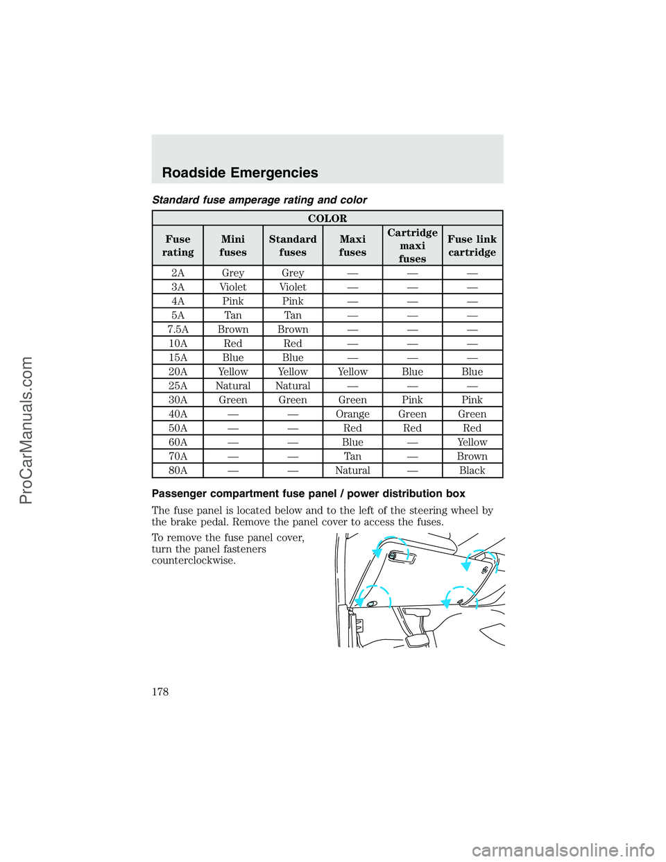
Standard fuse amperage rating and color
COLOR
Fuse
ratingMini
fusesStandard
fusesMaxi
fusesCartridge
maxi
fusesFuse link
cartridge
2A Grey Grey———
3A Violet Violet———
4A Pink Pink———
5A Tan Tan———
7.5A Brown Brown———
10A Red Red———
15A Blue Blue———
20A Yellow Yellow Yellow Blue Blue
25A Natural Natural———
30A Green Green Green Pink Pink
40A——Orange Green Green
50A——Red Red Red
60A——Blue—Yellow
70A——Ta n—Brown
80A——Natural—Black
Passenger compartment fuse panel / power distribution box
The fuse panel is located below and to the left of the steering wheel by
the brake pedal. Remove the panel cover to access the fuses.
To remove the fuse panel cover,
turn the panel fasteners
counterclockwise.
Roadside Emergencies
178
ProCarManuals.com
Page 184 of 280
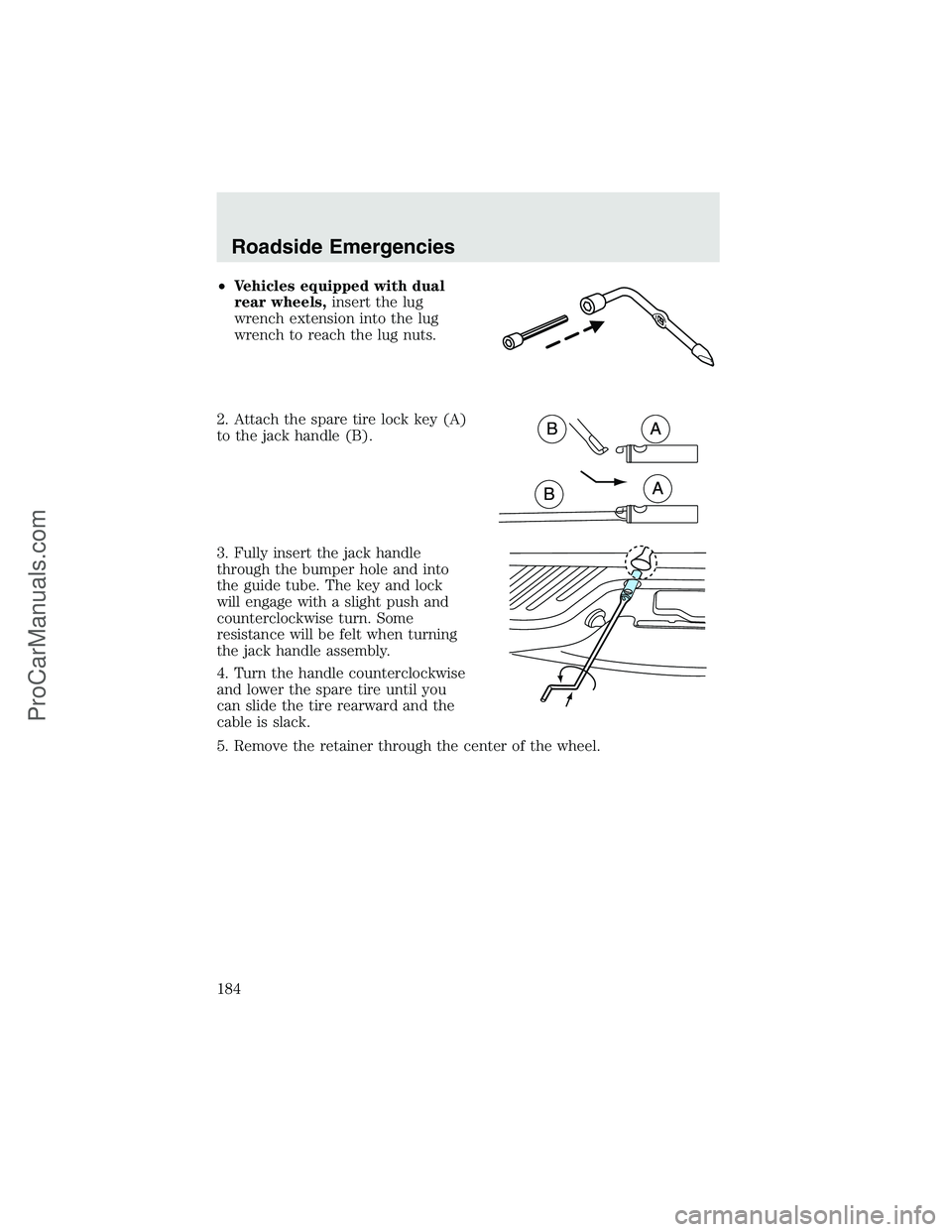
•Vehicles equipped with dual
rear wheels,insert the lug
wrench extension into the lug
wrench to reach the lug nuts.
2. Attach the spare tire lock key (A)
to the jack handle (B).
3. Fully insert the jack handle
through the bumper hole and into
the guide tube. The key and lock
will engage with a slight push and
counterclockwise turn. Some
resistance will be felt when turning
the jack handle assembly.
4. Turn the handle counterclockwise
and lower the spare tire until you
can slide the tire rearward and the
cable is slack.
5. Remove the retainer through the center of the wheel.
Roadside Emergencies
184
ProCarManuals.com
Page 186 of 280
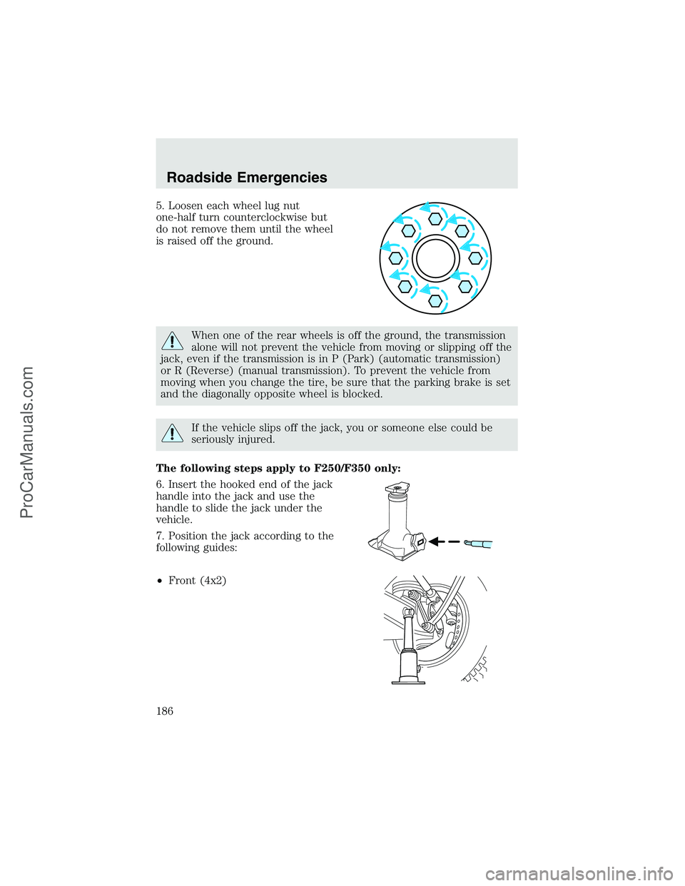
5. Loosen each wheel lug nut
one-half turn counterclockwise but
do not remove them until the wheel
is raised off the ground.
When one of the rear wheels is off the ground, the transmission
alone will not prevent the vehicle from moving or slipping off the
jack, even if the transmission is in P (Park) (automatic transmission)
or R (Reverse) (manual transmission). To prevent the vehicle from
moving when you change the tire, be sure that the parking brake is set
and the diagonally opposite wheel is blocked.
If the vehicle slips off the jack, you or someone else could be
seriously injured.
The following steps apply to F250/F350 only:
6. Insert the hooked end of the jack
handle into the jack and use the
handle to slide the jack under the
vehicle.
7. Position the jack according to the
following guides:
•Front (4x2)
Roadside Emergencies
186
ProCarManuals.com
Page 188 of 280
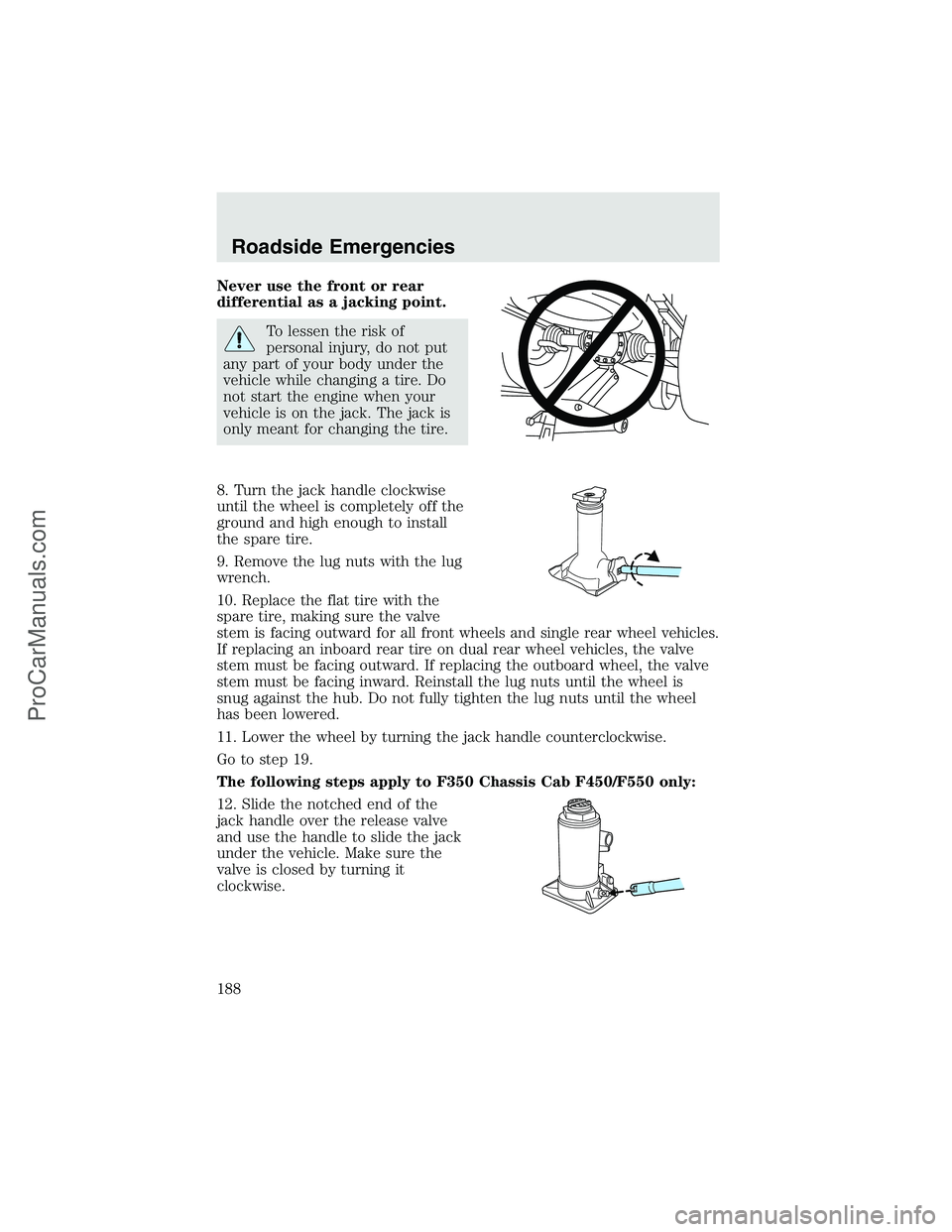
Never use the front or rear
differential as a jacking point.
To lessen the risk of
personal injury, do not put
any part of your body under the
vehicle while changing a tire. Do
not start the engine when your
vehicle is on the jack. The jack is
only meant for changing the tire.
8. Turn the jack handle clockwise
until the wheel is completely off the
ground and high enough to install
the spare tire.
9. Remove the lug nuts with the lug
wrench.
10. Replace the flat tire with the
spare tire, making sure the valve
stem is facing outward for all front wheels and single rear wheel vehicles.
If replacing an inboard rear tire on dual rear wheel vehicles, the valve
stem must be facing outward. If replacing the outboard wheel, the valve
stem must be facing inward. Reinstall the lug nuts until the wheel is
snug against the hub. Do not fully tighten the lug nuts until the wheel
has been lowered.
11. Lower the wheel by turning the jack handle counterclockwise.
Go to step 19.
The following steps apply to F350 Chassis Cab F450/F550 only:
12. Slide the notched end of the
jack handle over the release valve
and use the handle to slide the jack
under the vehicle. Make sure the
valve is closed by turning it
clockwise.
Roadside Emergencies
188
ProCarManuals.com
Page 190 of 280
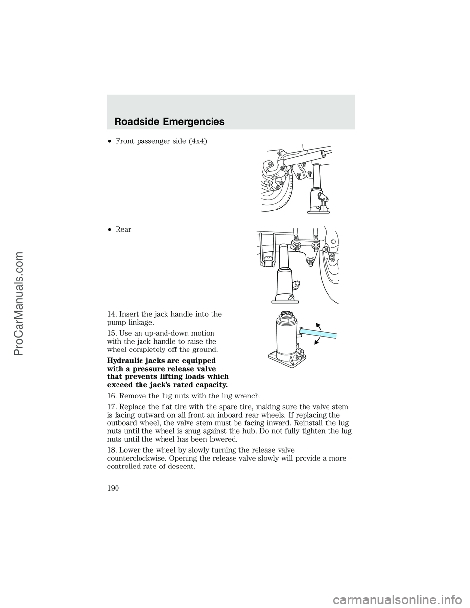
•Front passenger side (4x4)
•Rear
14. Insert the jack handle into the
pump linkage.
15. Use an up-and-down motion
with the jack handle to raise the
wheel completely off the ground.
Hydraulic jacks are equipped
with a pressure release valve
that prevents lifting loads which
exceed the jack’s rated capacity.
16. Remove the lug nuts with the lug wrench.
17. Replace the flat tire with the spare tire, making sure the valve stem
is facing outward on all front an inboard rear wheels. If replacing the
outboard wheel, the valve stem must be facing inward. Reinstall the lug
nuts until the wheel is snug against the hub. Do not fully tighten the lug
nuts until the wheel has been lowered.
18. Lower the wheel by slowly turning the release valve
counterclockwise. Opening the release valve slowly will provide a more
controlled rate of descent.
Roadside Emergencies
190
ProCarManuals.com
Page 192 of 280
When a wheel is installed, always remove any corrosion, dirt or
foreign materials present on the mounting surfaces of the wheel
or the surface of the front disc brake hub and rotor that contacts the
wheel. Installing wheels without correct metal-to-metal contact at the
wheel mounting surfaces can cause the wheel nuts to loosen and the
wheel to come off while the vehicle is in motion, resulting in loss of
control.
Stowing the flat/spare tire
1. Lay the tire on the ground with the valve stem facing in the direction
specified on the Tire Changing Instructions located with the jack
hardware.
2. Slide the wheel partially under the vehicle and install the retainer
through the wheel center. Pull on the cable to align the components at
the end of the cable.
3. Turn the jack handle clockwise until the tire is raised to its stowed
position underneath the vehicle. The effort to turn the jack handle
increases significantly and the spare tire carrier ratchets or slips when
the tire is raised to the maximum tightness. Tighten to the best of your
ability, to the point where the ratchet/slip occurs, if possible. The spare
tire carrier will not allow you to overtighten. If the spare tire carrier
ratchets or slips with little effort, take the vehicle to your dealer for
assistance at your earliest convenience.
4. Check that the tire lies flat against the frame and is properly
tightened. Try to push or pull, then turn the tire to be sure it will not
move. Loosen and retighten, if necessary. Failure to properly stow the
spare tire may result in failure of the winch cable and loss of the tire.
5. Repeat this tightness check procedure when servicing the spare tire
pressure (every six months, per scheduled maintenance guide), or at any
time that the spare tire is disturbed through service of other
components.
6. If removed, install the spare tire lock (if equipped) into the bumper
drive tube with the spare tire lock key (if equipped) and jack handle.
Roadside Emergencies
192
ProCarManuals.com
Page 221 of 280
3. Recheck the engine oil level. Make sure the oil level is not above the
MAX mark on the engine oil level indicator (dipstick).
4. Install the indicator and ensure it is fully seated.
5. Fully install the engine oil filler cap by turning the filler cap clockwise
1/4 of a turn until three clicks are heard or until the cap is fully seated.
To avoid possible oil loss, DO NOT operate the vehicle with the
engine oil level indicator and/or the engine oil filler cap removed.
Engine oil and filter recommendations
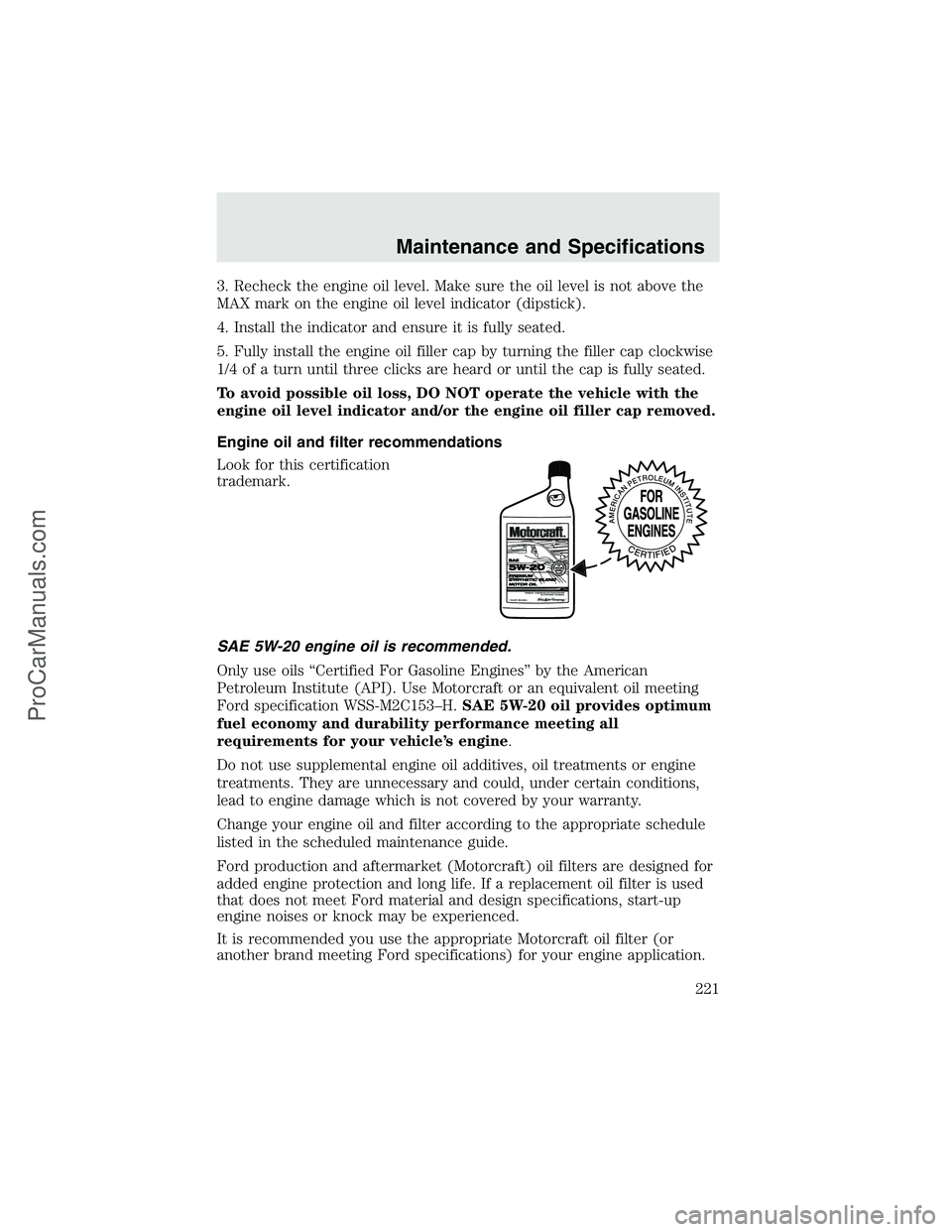
Look for this certification
trademark.
SAE 5W-20 engine oil is recommended.
Only use oils“Certified For Gasoline Engines”by the American
Petroleum Institute (API). Use Motorcraft or an equivalent oil meeting
Ford specification WSS-M2C153–H.SAE 5W-20 oil provides optimum
fuel economy and durability performance meeting all
requirements for your vehicle’s engine.
Do not use supplemental engine oil additives, oil treatments or engine
treatments. They are unnecessary and could, under certain conditions,
lead to engine damage which is not covered by your warranty.
Change your engine oil and filter according to the appropriate schedule
listed in the scheduled maintenance guide.
Ford production and aftermarket (Motorcraft) oil filters are designed for
added engine protection and long life. If a replacement oil filter is used
that does not meet Ford material and design specifications, start-up
engine noises or knock may be experienced.
It is recommended you use the appropriate Motorcraft oil filter (or
another brand meeting Ford specifications) for your engine application.
Maintenance and Specifications
221
ProCarManuals.com
Page 223 of 280
When lifting a plastic-cased battery, excessive pressure on the
end walls could cause acid to flow through the vent caps,
resulting in personal injury and/or damage to the vehicle or battery.
Lift the battery with a battery carrier or with your hands on opposite
corners.
Keep batteries out of reach of children. Batteries contain sulfuric
acid. Avoid contact with skin, eyes or clothing. Shield your eyes
when working near the battery to protect against possible splashing of
acid solution. In case of acid contact with skin or eyes, flush
immediately with water for a minimum of 15 minutes and get prompt
medical attention. If acid is swallowed, call a physician immediately.
Battery posts, terminals and related accessories contain lead and
lead compounds.Wash hands after handling.
For information on transmission operation after the battery has been
disconnected see“Shift strategy”in the driving section.
Because your vehicle’s engine is also electronically controlled by a
computer, some control conditions are maintained by power from the
battery. When the battery is disconnected or a new battery is installed,
the engine must relearn its idle and fuel trim strategy for optimum
driveability and performance. To begin this process:
1. With the vehicle at a complete stop, set the parking brake.
2. Put the gearshift in P (Park) (automatic transmission) or the neutral
position (manual transmission), turn off all accessories and start the
engine.
3. Run the engine until it reaches normal operating temperature.
4. Allow the engine to idle for at least one minute.
5. Turn the A/C on and allow the engine to idle for at least one minute.
6. Drive the vehicle to complete the relearning process.
•The vehicle may need to be driven 16 km (10 miles) or more to
relearn the idle and fuel trim strategy.
•If you do not allow the engine to relearn its idle trim, the idle
quality of your vehicle may be adversely affected until the idle
trim is eventually relearned.
If the battery has been disconnected or a new battery has been installed,
the clock and the preset radio stations must be reset once the battery is
reconnected.
Maintenance and Specifications
223
ProCarManuals.com