Page 177 of 272

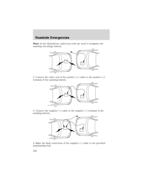
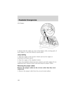
Canadian customers who require roadside assistance, call
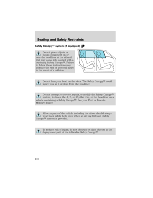
1–800–665–2006.
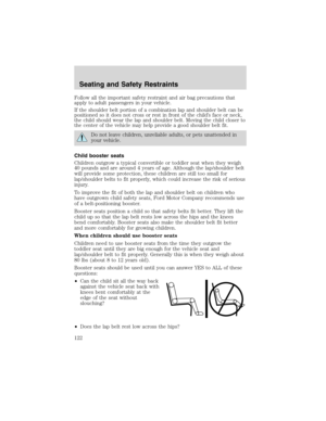
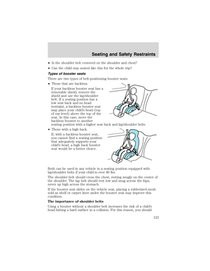
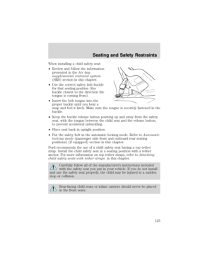
If you need to arrange roadside assistance for yourself, Ford Motor
Company will reimburse a reasonable amount. To obtain reimbursement
information, U.S. Ford or Mercury vehicles customers call
1-800-241-3673; Lincoln vehicle customers call 1–800–521–4140.
Canadian customers who need to obtain reimbursement information, call
1–800–665–2006.
ROADSIDE COVERAGE BEYOND BASIC WARRANTY
In the United States, you may purchase additional roadside assistance
coverage beyond this period through the Ford Auto Club by contacting
your Ford or Lincoln Mercury dealer.
Similarly in Canada, for uninterrupted Roadside Assistance coverage, you
may purchase extended coverage prior to your Basic Warranty’s Roadside
Assistance expiring. For more information and enrollment, contact
1–877–294–2582 or visit our website at www.ford.ca.
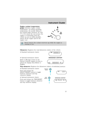
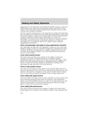
HAZARD FLASHER
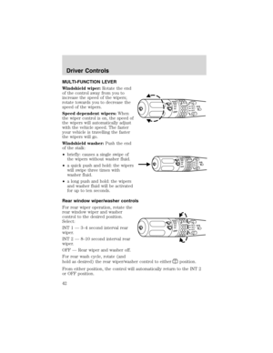
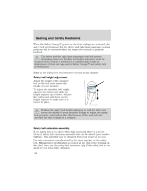
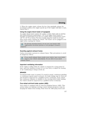
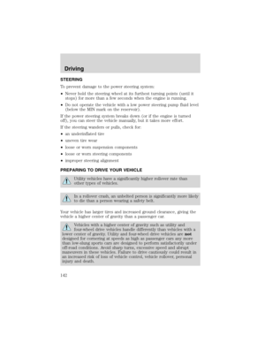
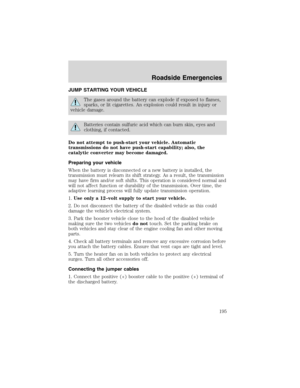
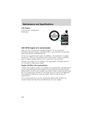
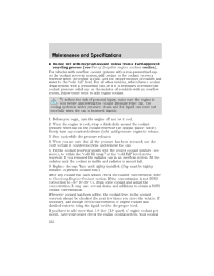
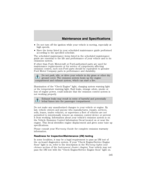
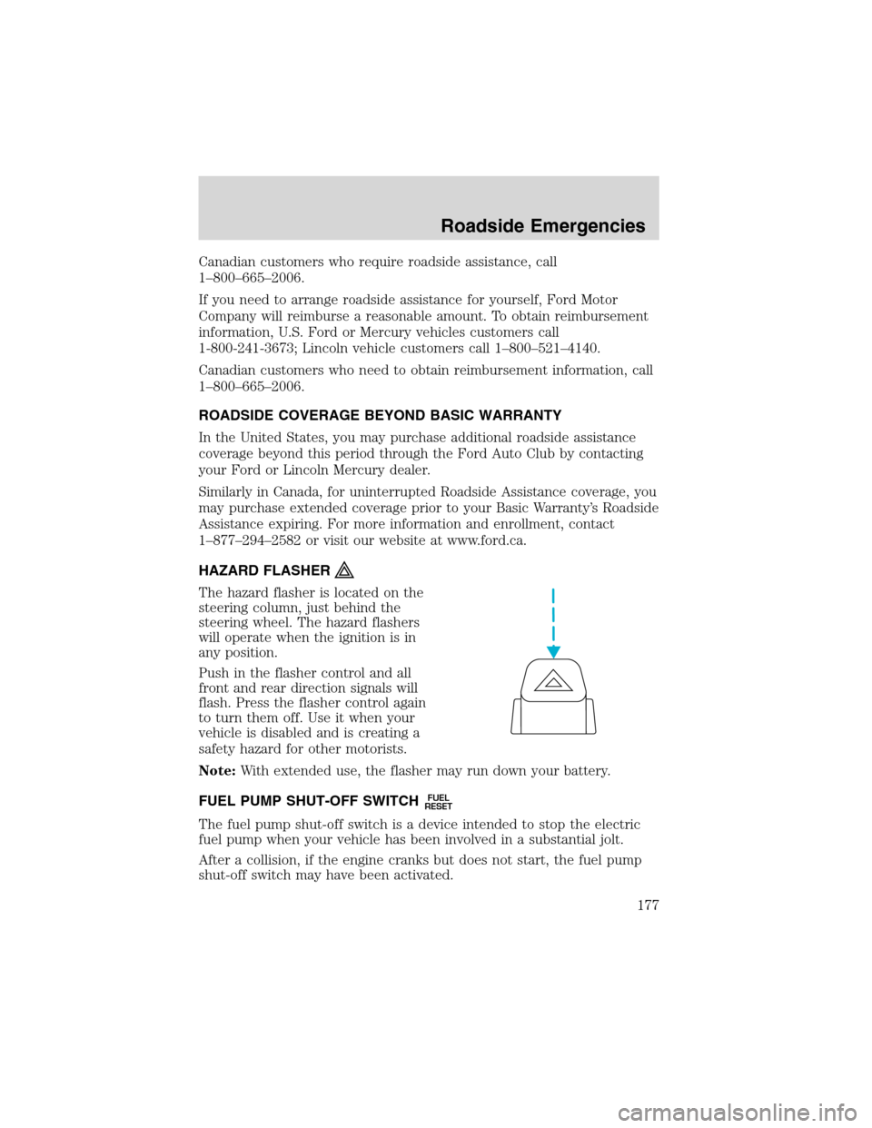
The hazard flasher is located on the
steering column, just behind the
steering wheel. The hazard flashers
will operate when the ignition is in
any position.
Push in the flasher control and all
front and rear direction signals will
flash. Press the flasher control again
to turn them off. Use it when your
vehicle is disabled and is creating a
safety hazard for other motorists.
Note:With extended use, the flasher may run down your battery.
FUEL PUMP SHUT-OFF SWITCH
FUEL
RESET
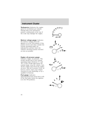
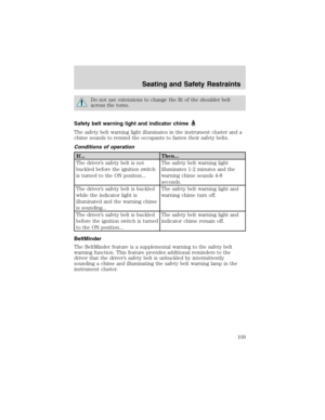
The fuel pump shut-off switch is a device intended to stop the electric
fuel pump when your vehicle has been involved in a substantial jolt.
After a collision, if the engine cranks but does not start, the fuel pump
shut-off switch may have been activated.
Roadside Emergencies
177
Page 178 of 272
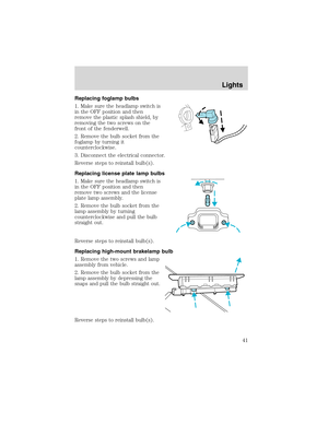
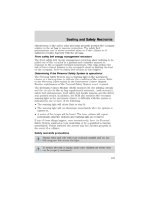
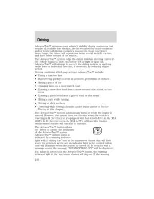
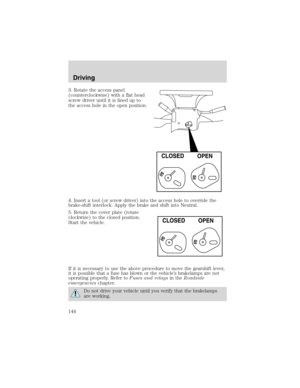
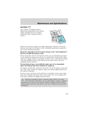
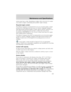
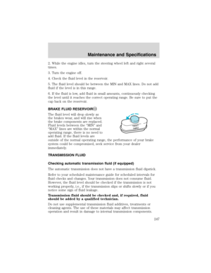
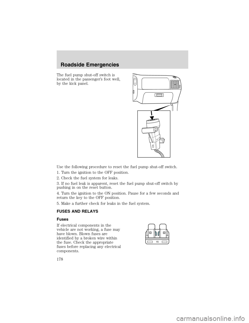
The fuel pump shut-off switch is
located in the passenger’s foot well,
by the kick panel.
Use the following procedure to reset the fuel pump shut-off switch.
1. Turn the ignition to the OFF position.
2. Check the fuel system for leaks.
3. If no fuel leak is apparent, reset the fuel pump shut-off switch by
pushing in on the reset button.
4. Turn the ignition to the ON position. Pause for a few seconds and
return the key to the OFF position.
5. Make a further check for leaks in the fuel system.
FUSES AND RELAYS
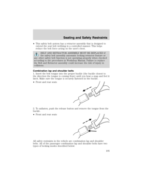
Fuses
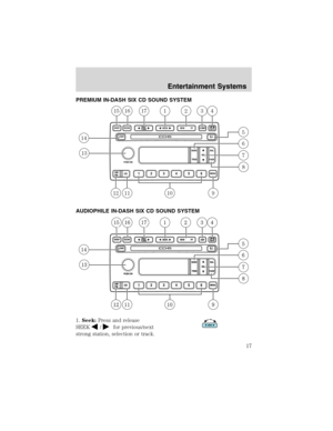
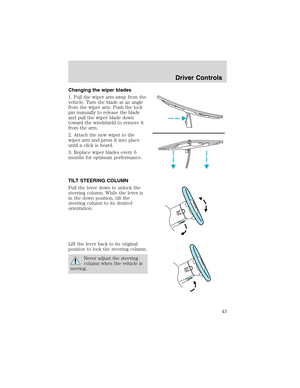
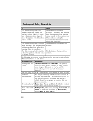
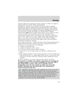
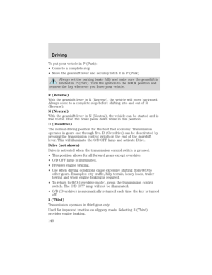
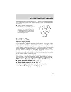
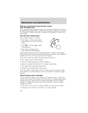
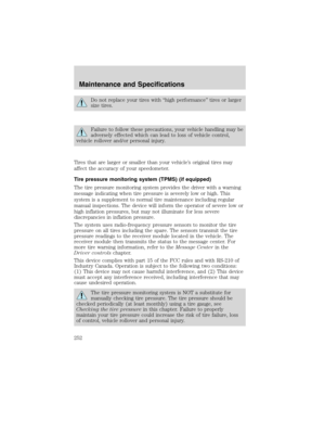
If electrical components in the
vehicle are not working, a fuse may
have blown. Blown fuses are
identified by a broken wire within
the fuse. Check the appropriate
fuses before replacing any electrical
components.
15
Roadside Emergencies
178
Page 179 of 272
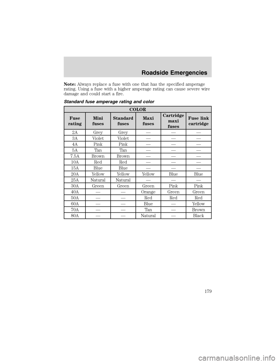
Note:Always replace a fuse with one that has the specified amperage
rating. Using a fuse with a higher amperage rating can cause severe wire
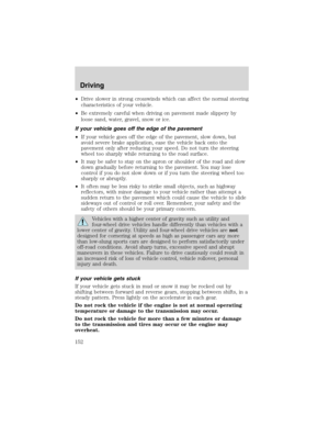
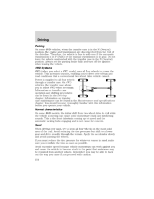
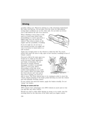
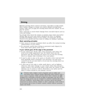
damage and could start a fire.
Standard fuse amperage rating and color
COLOR
Fuse
ratingMini
fusesStandard
fusesMaxi
fusesCartridge
maxi
fusesFuse link
cartridge
2A Grey Grey———
3A Violet Violet———
4A Pink Pink———
5A Tan Tan———
7.5A Brown Brown———
10A Red Red———
15A Blue Blue———
20A Yellow Yellow Yellow Blue Blue
25A Natural Natural———
30A Green Green Green Pink Pink
40A——Orange Green Green
50A——Red Red Red
60A——Blue—Yellow
70A——Ta n—Brown
80A——Natural—Black
Roadside Emergencies
179
Page 180 of 272
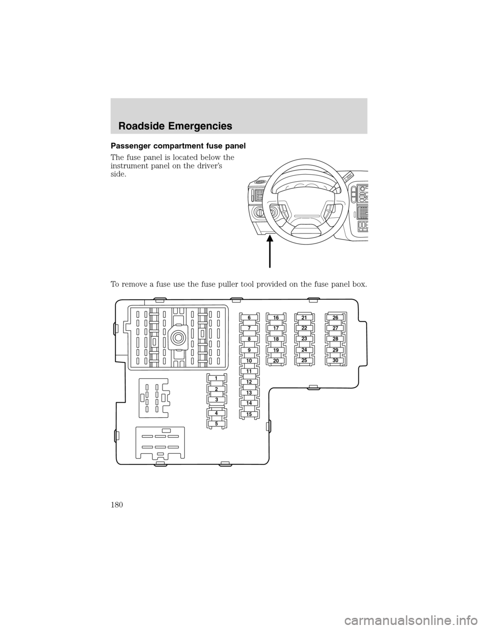
Passenger compartment fuse panel
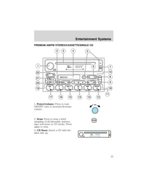
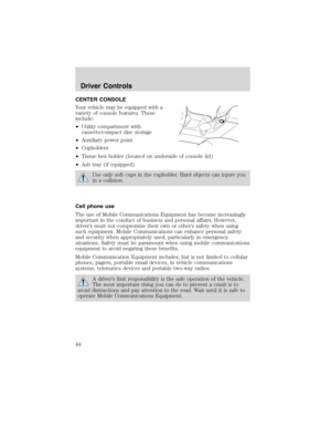
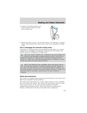
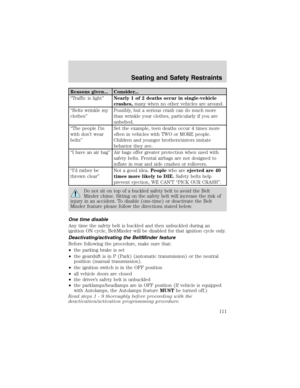
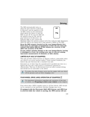
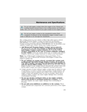
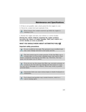
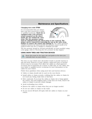
The fuse panel is located below the
instrument panel on the driver’s
side.
To remove a fuse use the fuse puller tool provided on the fuse panel box.
161621 26
27
28
29
30 22
23
24
25 17
18
19
20 7
8
9
10
11
12
13
14
15 2
3
4
5
Roadside Emergencies
180
Page 181 of 272

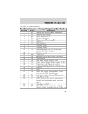
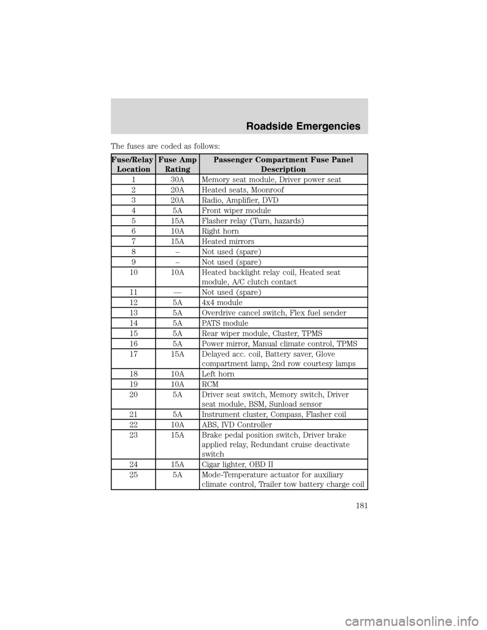
The fuses are coded as follows:
Fuse/Relay
LocationFuse Amp
RatingPassenger Compartment Fuse Panel
Description
1 30A Memory seat module, Driver power seat
2 20A Heated seats, Moonroof
3 20A Radio, Amplifier, DVD
4 5A Front wiper module
5 15A Flasher relay (Turn, hazards)
6 10A Right horn
7 15A Heated mirrors
8–Not used (spare)
9–Not used (spare)
10 10A Heated backlight relay coil, Heated seat
module, A/C clutch contact
11—Not used (spare)
12 5A 4x4 module
13 5A Overdrive cancel switch, Flex fuel sender
14 5A PATS module
15 5A Rear wiper module, Cluster, TPMS
16 5A Power mirror, Manual climate control, TPMS
17 15A Delayed acc. coil, Battery saver, Glove
compartment lamp, 2nd row courtesy lamps
18 10A Left horn
19 10A RCM
20 5A Driver seat switch, Memory switch, Driver
seat module, BSM, Sunload sensor
21 5A Instrument cluster, Compass, Flasher coil
22 10A ABS, IVD Controller
23 15A Brake pedal position switch, Driver brake
applied relay, Redundant cruise deactivate
switch
24 15A Cigar lighter, OBD II
25 5A Mode-Temperature actuator for auxiliary
climate control, Trailer tow battery charge coil
Roadside Emergencies
181
Page 182 of 272
Fuse/Relay
LocationFuse Amp
RatingPassenger Compartment Fuse Panel
Description
26 7.5A Park aid, Brake shift interlock, Approach lamp
relay coil, IVD switch
27 7.5A Electrochromatic mirror, Digital transmission
range sensor - backup lamps
28 5A Radio (Start)/DVD (Start)
29 10A Digital transmission range sensor, PWR feed
to fuse #28 (Start feed)
30 5A Daytime Running Lamps (DRL), Remote
solenoid, DEATC climate controller, Manual
climate control, Manual climate control temp
blend actuator
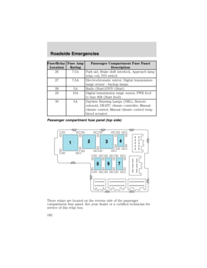
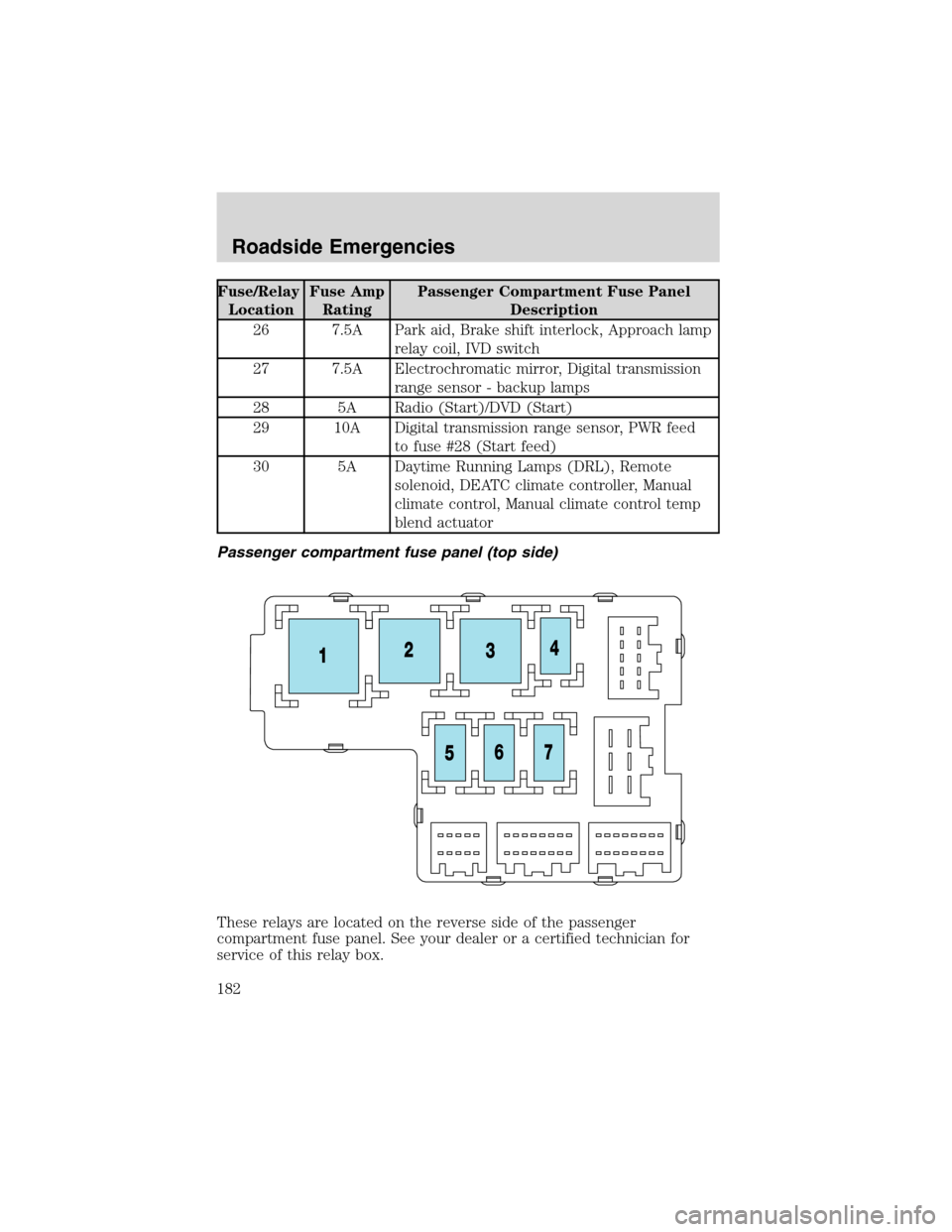
Passenger compartment fuse panel (top side)
These relays are located on the reverse side of the passenger
compartment fuse panel. See your dealer or a certified technician for
service of this relay box.
Roadside Emergencies
182
Page 183 of 272
Fuse/Relay Location Description
Relay 1 Flasher relay
Relay 2 Rear defrost
Relay 3 Delayed accessory relay
Relay 4 Open
Relay 5 Battery saver
Relay 6 Open
Relay 7 Open
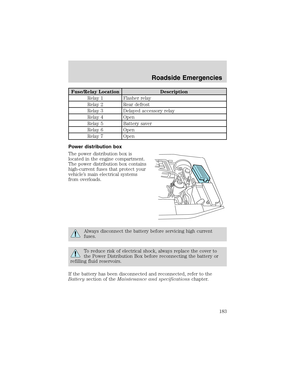
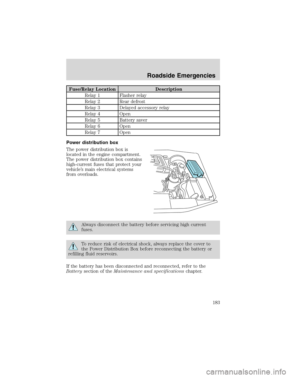
Power distribution box
The power distribution box is
located in the engine compartment.
The power distribution box contains
high-current fuses that protect your
vehicle’s main electrical systems
from overloads.
Always disconnect the battery before servicing high current
fuses.
To reduce risk of electrical shock, always replace the cover to
the Power Distribution Box before reconnecting the battery or
refilling fluid reservoirs.
If the battery has been disconnected and reconnected, refer to the
Batterysection of theMaintenance and specificationschapter.
Roadside Emergencies
183
Page 184 of 272
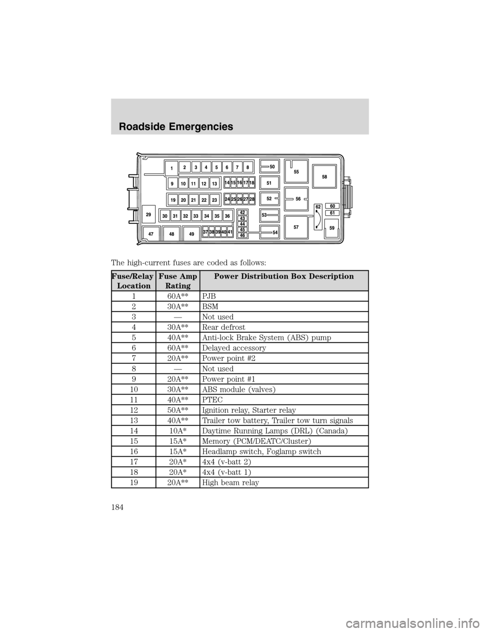
The high-current fuses are coded as follows:
Fuse/Relay
LocationFuse Amp
RatingPower Distribution Box Description
1 60A** PJB
2 30A** BSM
3—Not used
4 30A** Rear defrost
5 40A** Anti-lock Brake System (ABS) pump
6 60A** Delayed accessory
7 20A** Power point #2
8—Not used
9 20A** Power point #1
10 30A** ABS module (valves)
11 40A** PTEC
12 50A** Ignition relay, Starter relay
13 40A** Trailer tow battery, Trailer tow turn signals
14 10A* Daytime Running Lamps (DRL) (Canada)
15 15A* Memory (PCM/DEATC/Cluster)
16 15A* Headlamp switch, Foglamp switch
17 20A* 4x4 (v-batt 2)
18 20A* 4x4 (v-batt 1)
19 20A** High beam relay
Roadside Emergencies
184