2003 DODGE RAM C1 connector
[x] Cancel search: C1 connectorPage 2809 of 2895
The refrigerant system will remain chemically sta-
ble as long as pure, moisture-free R-134a refrigerant
and refrigerant oil is used. Dirt, moisture, or air can
upset this chemical stability. Operational troubles or
serious damage can occur if foreign material is
present in the refrigerant system.
When it is necessary to open the refrigerant sys-
tem, have everything needed to service the system
ready. The refrigerant system should not be left open
to the atmosphere any longer than necessary. Cap or
plug all lines and fittings as soon as they are opened
to prevent the entrance of dirt and moisture. All lines
and components in parts stock should be capped or
sealed until they are to be installed.
All tools, including the refrigerant recycling equip-
ment, the manifold gauge set, and test hoses should
be kept clean and dry. All tools and equipment must
be designed for R-134a refrigerant.
STANDARD PROCEDURE
STANDARD PROCEDURE - REFRIGERANT
SYSTEM SERVICE EQUIPMENT
WARNING: REVIEW THE WARNINGS AND CAU-
TIONS IN THE FRONT OF THIS SECTION BEFORE
PERFORMING THE FOLLOWING OPERATION.
(Refer to 24 - HEATING & AIR CONDITIONING/
PLUMBING - WARNING) (Refer to 24 - HEATING &
AIR CONDITIONING/PLUMBING - CAUTION)
When servicing the air conditioning system, a
R-134a refrigerant recovery/recycling/charging sta-
tion that meets SAE Standard J2210 must be used.
Contact an automotive service equipment supplier for
refrigerant recovery/recycling/charging equipment.
Refer to the operating instructions supplied by the
equipment manufacturer for proper care and use of
this equipment.
A manifold gauge set may be needed with some
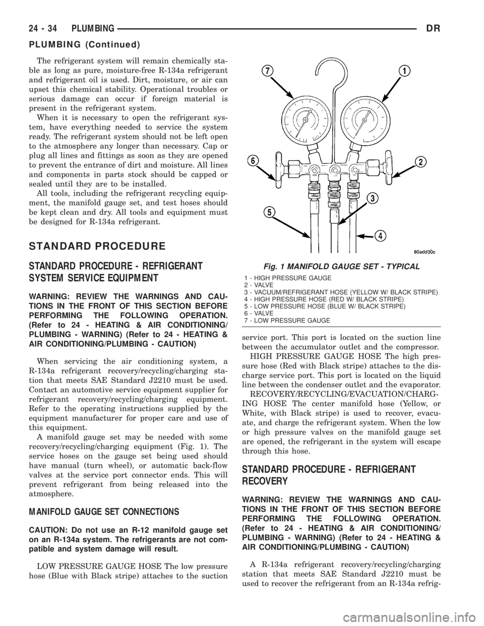
recovery/recycling/charging equipment (Fig. 1). The
service hoses on the gauge set being used should
have manual (turn wheel), or automatic back-flow
valves at the service port connector ends. This will
prevent refrigerant from being released into the
atmosphere.
MANIFOLD GAUGE SET CONNECTIONS
CAUTION: Do not use an R-12 manifold gauge set
on an R-134a system. The refrigerants are not com-
patible and system damage will result.
LOW PRESSURE GAUGE HOSE The low pressure
hose (Blue with Black stripe) attaches to the suctionservice port. This port is located on the suction line
between the accumulator outlet and the compressor.
HIGH PRESSURE GAUGE HOSE The high pres-
sure hose (Red with Black stripe) attaches to the dis-
charge service port. This port is located on the liquid
line between the condenser outlet and the evaporator.
RECOVERY/RECYCLING/EVACUATION/CHARG-
ING HOSE The center manifold hose (Yellow, or
White, with Black stripe) is used to recover, evacu-
ate, and charge the refrigerant system. When the low
or high pressure valves on the manifold gauge set
are opened, the refrigerant in the system will escape
through this hose.
STANDARD PROCEDURE - REFRIGERANT
RECOVERY
WARNING: REVIEW THE WARNINGS AND CAU-
TIONS IN THE FRONT OF THIS SECTION BEFORE
PERFORMING THE FOLLOWING OPERATION.
(Refer to 24 - HEATING & AIR CONDITIONING/
PLUMBING - WARNING) (Refer to 24 - HEATING &
AIR CONDITIONING/PLUMBING - CAUTION)
A R-134a refrigerant recovery/recycling/charging
station that meets SAE Standard J2210 must be
used to recover the refrigerant from an R-134a refrig-
Fig. 1 MANIFOLD GAUGE SET - TYPICAL
1 - HIGH PRESSURE GAUGE
2 - VALVE
3 - VACUUM/REFRIGERANT HOSE (YELLOW W/ BLACK STRIPE)
4 - HIGH PRESSURE HOSE (RED W/ BLACK STRIPE)
5 - LOW PRESSURE HOSE (BLUE W/ BLACK STRIPE)
6 - VALVE
7 - LOW PRESSURE GAUGE
24 - 34 PLUMBINGDR
PLUMBING (Continued)
Page 2812 of 2895
FRIGERANT - STANDARD PROCEDURE) and
(Refer to 24 - HEATING & AIR CONDITIONING/
PLUMBING/REFRIGERANT - STANDARD PROCE-
DURE). If the liquid slugging condition continues
replace the accumulator(Refer to 24 - HEATING &
AIR CONDITIONING/PLUMBING/ACCUMULATOR
- REMOVAL). If after replaceing the accumulator the
slugging condition still exists then replace the com-
pressor.(Refer to 24 - HEATING & AIR CONDITION-
ING/PLUMBING/A/C COMPRESSOR - REMOVAL)
(7) If the noise continues, replace the compressor
and repeat Step 1.
REMOVAL
REMOVAL
WARNING: REVIEW THE WARNINGS AND CAU-
TIONS IN THE FRONT OF THIS SECTION BEFORE
PERFORMING THE FOLLOWING OPERATION.
(Refer to 24 - HEATING & AIR CONDITIONING/
PLUMBING - WARNING) (Refer to 24 - HEATING &
AIR CONDITIONING/PLUMBING - CAUTION)
The compressor may be removed and repositioned
without disconnecting the refrigerant lines or dis-
charging the refrigerant system. Discharging is not
necessary if servicing the compressor clutch or clutch
coil, the engine, the cylinder head, or the generator.
(1) Recover the refrigerant from the refrigerant
system. (Refer to 24 - HEATING & AIR CONDI-
TIONING/PLUMBING - STANDARD PROCEDURE -
REFRIGERANT RECOVERY)
(2) Disconnect and isolate the battery negative
cable.
(3) Remove the serpentine drive belt(Refer to 7 -
COOLING/ACCESSORY DRIVE/DRIVE BELTS -
REMOVAL).
(4) Unplug the compressor clutch coil wire harness
connector.
(5) Remove the suction and discharge refrigerant
line manifold from the compressor. (Refer to 24 -
HEATING & AIR CONDITIONING/PLUMBING/
SUCTION LINE - REMOVAL) (Refer to 24 - HEAT-
ING & AIR CONDITIONING/PLUMBING/A/C
DISCHARGE LINE - REMOVAL) Install plugs in, or
tape over all of the opened refrigerant fittings.
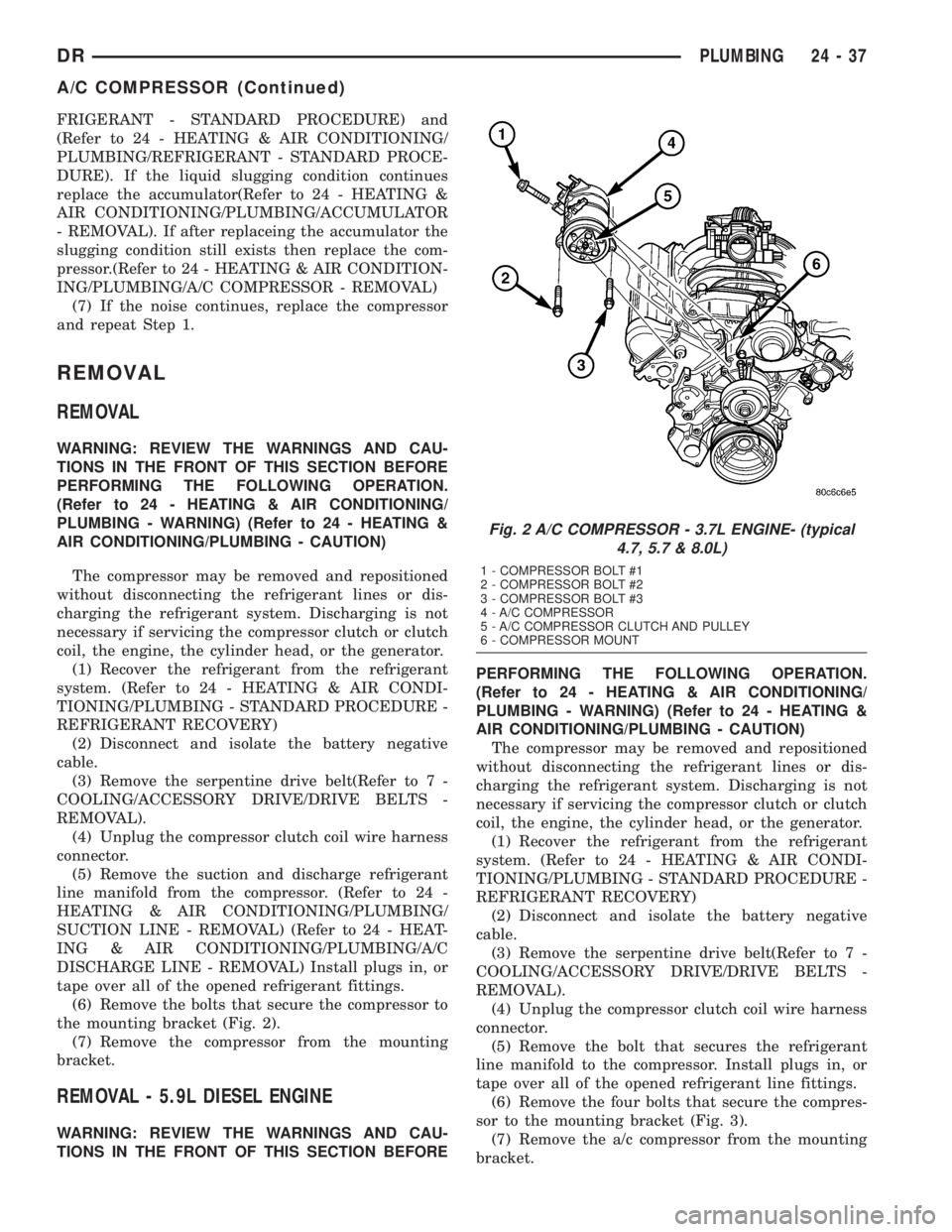
(6) Remove the bolts that secure the compressor to
the mounting bracket (Fig. 2).
(7) Remove the compressor from the mounting
bracket.
REMOVAL - 5.9L DIESEL ENGINE
WARNING: REVIEW THE WARNINGS AND CAU-
TIONS IN THE FRONT OF THIS SECTION BEFOREPERFORMING THE FOLLOWING OPERATION.
(Refer to 24 - HEATING & AIR CONDITIONING/
PLUMBING - WARNING) (Refer to 24 - HEATING &
AIR CONDITIONING/PLUMBING - CAUTION)
The compressor may be removed and repositioned
without disconnecting the refrigerant lines or dis-
charging the refrigerant system. Discharging is not
necessary if servicing the compressor clutch or clutch
coil, the engine, the cylinder head, or the generator.
(1) Recover the refrigerant from the refrigerant
system. (Refer to 24 - HEATING & AIR CONDI-
TIONING/PLUMBING - STANDARD PROCEDURE -
REFRIGERANT RECOVERY)
(2) Disconnect and isolate the battery negative
cable.
(3) Remove the serpentine drive belt(Refer to 7 -
COOLING/ACCESSORY DRIVE/DRIVE BELTS -
REMOVAL).
(4) Unplug the compressor clutch coil wire harness
connector.
(5) Remove the bolt that secures the refrigerant
line manifold to the compressor. Install plugs in, or
tape over all of the opened refrigerant line fittings.
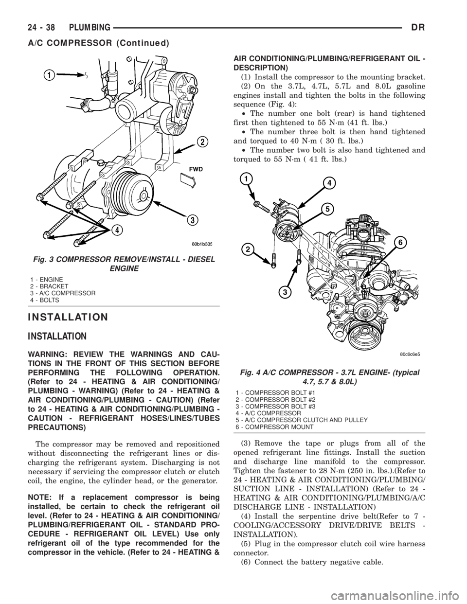
(6) Remove the four bolts that secure the compres-
sor to the mounting bracket (Fig. 3).
(7) Remove the a/c compressor from the mounting
bracket.
Fig. 2 A/C COMPRESSOR - 3.7L ENGINE- (typical
4.7, 5.7 & 8.0L)
1 - COMPRESSOR BOLT #1
2 - COMPRESSOR BOLT #2
3 - COMPRESSOR BOLT #3
4 - A/C COMPRESSOR
5 - A/C COMPRESSOR CLUTCH AND PULLEY
6 - COMPRESSOR MOUNT
DRPLUMBING 24 - 37
A/C COMPRESSOR (Continued)
Page 2813 of 2895
INSTALLATION
INSTALLATION
WARNING: REVIEW THE WARNINGS AND CAU-
TIONS IN THE FRONT OF THIS SECTION BEFORE
PERFORMING THE FOLLOWING OPERATION.
(Refer to 24 - HEATING & AIR CONDITIONING/
PLUMBING - WARNING) (Refer to 24 - HEATING &
AIR CONDITIONING/PLUMBING - CAUTION) (Refer
to 24 - HEATING & AIR CONDITIONING/PLUMBING -
CAUTION - REFRIGERANT HOSES/LINES/TUBES
PRECAUTIONS)
The compressor may be removed and repositioned
without disconnecting the refrigerant lines or dis-
charging the refrigerant system. Discharging is not
necessary if servicing the compressor clutch or clutch
coil, the engine, the cylinder head, or the generator.
NOTE: If a replacement compressor is being
installed, be certain to check the refrigerant oil
level. (Refer to 24 - HEATING & AIR CONDITIONING/
PLUMBING/REFRIGERANT OIL - STANDARD PRO-
CEDURE - REFRIGERANT OIL LEVEL) Use only
refrigerant oil of the type recommended for the
compressor in the vehicle. (Refer to 24 - HEATING &AIR CONDITIONING/PLUMBING/REFRIGERANT OIL -
DESCRIPTION)
(1) Install the compressor to the mounting bracket.
(2) On the 3.7L, 4.7L, 5.7L and 8.0L gasoline
engines install and tighten the bolts in the following
sequence (Fig. 4):
²The number one bolt (rear) is hand tightened
first then tightened to 55 N´m (41 ft. lbs.)
²The number three bolt is then hand tightened
and torqued to 40 N´m ( 30 ft. lbs.)
²The number two bolt is also hand tightened and
torqued to 55 N´m ( 41 ft. lbs.)
(3) Remove the tape or plugs from all of the
opened refrigerant line fittings. Install the suction
and discharge line manifold to the compressor.
Tighten the fastener to 28 N´m (250 in. lbs.).(Refer to
24 - HEATING & AIR CONDITIONING/PLUMBING/
SUCTION LINE - INSTALLATION) (Refer to 24 -
HEATING & AIR CONDITIONING/PLUMBING/A/C
DISCHARGE LINE - INSTALLATION)
(4) Install the serpentine drive belt(Refer to 7 -
COOLING/ACCESSORY DRIVE/DRIVE BELTS -
INSTALLATION).
(5) Plug in the compressor clutch coil wire harness
connector.
(6) Connect the battery negative cable.
Fig. 3 COMPRESSOR REMOVE/INSTALL - DIESEL
ENGINE
1 - ENGINE
2 - BRACKET
3 - A/C COMPRESSOR
4 - BOLTS
Fig. 4 A/C COMPRESSOR - 3.7L ENGINE- (typical
4.7, 5.7 & 8.0L)
1 - COMPRESSOR BOLT #1
2 - COMPRESSOR BOLT #2
3 - COMPRESSOR BOLT #3
4 - A/C COMPRESSOR
5 - A/C COMPRESSOR CLUTCH AND PULLEY
6 - COMPRESSOR MOUNT
24 - 38 PLUMBINGDR
A/C COMPRESSOR (Continued)
Page 2814 of 2895
(7) Evacuate the refrigerant system. (Refer to 24 -
HEATING & AIR CONDITIONING/PLUMBING -
STANDARD PROCEDURE - REFRIGERANT SYS-
TEM EVACUATE)
(8) Charge the refrigerant system. (Refer to 24 -
HEATING & AIR CONDITIONING/PLUMBING -
STANDARD PROCEDURE - REFRIGERANT SYS-
TEM CHARGE)
INSTALLATION - 5.9L DIESEL ENGINE
WARNING: REVIEW THE WARNINGS AND CAU-
TIONS IN THE FRONT OF THIS SECTION BEFORE
PERFORMING THE FOLLOWING OPERATION.
(Refer to 24 - HEATING & AIR CONDITIONING/
PLUMBING - WARNING) (Refer to 24 - HEATING &
AIR CONDITIONING/PLUMBING - CAUTION)(Refer to
24 - HEATING & AIR CONDITIONING/PLUMBING -
CAUTION - REFRIGERANT HOSES/LINES/TUBES
PRECAUTIONS)
NOTE: If a replacement compressor is being
installed, be certain to check the refrigerant oil
level. (Refer to 24 - HEATING & AIR CONDITIONING/
PLUMBING/REFRIGERANT OIL - STANDARD PRO-
CEDURE) Use only refrigerant oil of the type
recommended for the compressor in the vehicle.
(Refer to 24 - HEATING & AIR CONDITIONING/
PLUMBING/REFRIGERANT OIL - DESCRIPTION)
(1) Install the compressor to the mounting bracket.
Tighten the four mounting bolts to 24 N´m (210 in.
lbs.).
(2) Remove the tape or plugs from all of the
opened refrigerant line fittings. Install the suction
and discharge line manifold to the compressor. (Refer
to 24 - HEATING & AIR CONDITIONING/PLUMB-
ING/A/C SUCTION AND DISCHARGE LINE -
INSTALLATION)
(3) Install the serpentine drive belt(Refer to 7 -
COOLING/ACCESSORY DRIVE/DRIVE BELTS -
INSTALLATION).
(4) Plug in the compressor clutch coil wire harness
connector.
(5) Connect the battery negative cable.
(6) Evacuate the refrigerant system. (Refer to 24 -
HEATING & AIR CONDITIONING/PLUMBING -
STANDARD PROCEDURE - REFRIGERANT SYS-
TEM EVACUATE)
(7) Charge the refrigerant system. (Refer to 24 -
HEATING & AIR CONDITIONING/PLUMBING -
STANDARD PROCEDURE - REFRIGERANT SYS-
TEM CHARGE)
A/C CONDENSER
DESCRIPTION
The condenser is located in the air flow next to the
engine cooling radiator. The condenser is a heat
exchanger that allows the high-pressure refrigerant
gas being discharged by the compressor to give up its
heat to the air passing over the condenser fins.
OPERATION
When the refrigerant gas gives up its heat, it con-
denses. When the refrigerant leaves the condenser, it
has become a high-pressure liquid refrigerant. The
volume of air flowing over the condenser fins is crit-
ical to the proper cooling performance of the air con-
ditioning system. Therefore, it is important that
there are no objects placed in front of the radiator
grille openings in the front of the vehicle or foreign
material on the condenser fins that might obstruct
proper air flow. Also, any factory-installed air seals or
shrouds must be properly reinstalled following radia-
tor or condenser service.
The condenser cannot be repaired and, if faulty or
damaged, it must be replaced.
REMOVAL
REMOVAL - 3.7, 4.7 and 5.7L ENGINES
WARNING: REVIEW THE WARNINGS AND CAU-
TIONS IN THE FRONT OF THIS SECTION BEFORE
PERFORMING THE FOLLOWING OPERATION.
(Refer to 24 - HEATING & AIR CONDITIONING/
PLUMBING - WARNING) (Refer to 24 - HEATING &
AIR CONDITIONING/PLUMBING - CAUTION)
(1) Disconnect and isolate the battery negative
cable.
(2) Recover the refrigerant from the refrigerant
system. (Refer to 24 - HEATING & AIR CONDI-
TIONING/PLUMBING - STANDARD PROCEDURE -
REFRIGERANT RECOVERY)
(3) Disconnect the discharge line refrigerant line
fitting at the condenser inlet. (Refer to 24 - HEAT-
ING & AIR CONDITIONING/PLUMBING - STAN-
DARD PROCEDURE - A/C LINE COUPLERS)
Install plugs in, or tape over all of the opened refrig-
erant line fittings.
(4) Disconnect the liquid line refrigerant line fit-
ting at the condenser outlet. (Refer to 24 - HEATING
& AIR CONDITIONING/PLUMBING - STANDARD
PROCEDURE - A/C LINE COUPLERS) Install plugs
in, or tape over all of the opened refrigerant line fit-
tings.
DRPLUMBING 24 - 39
A/C COMPRESSOR (Continued)
Page 2815 of 2895
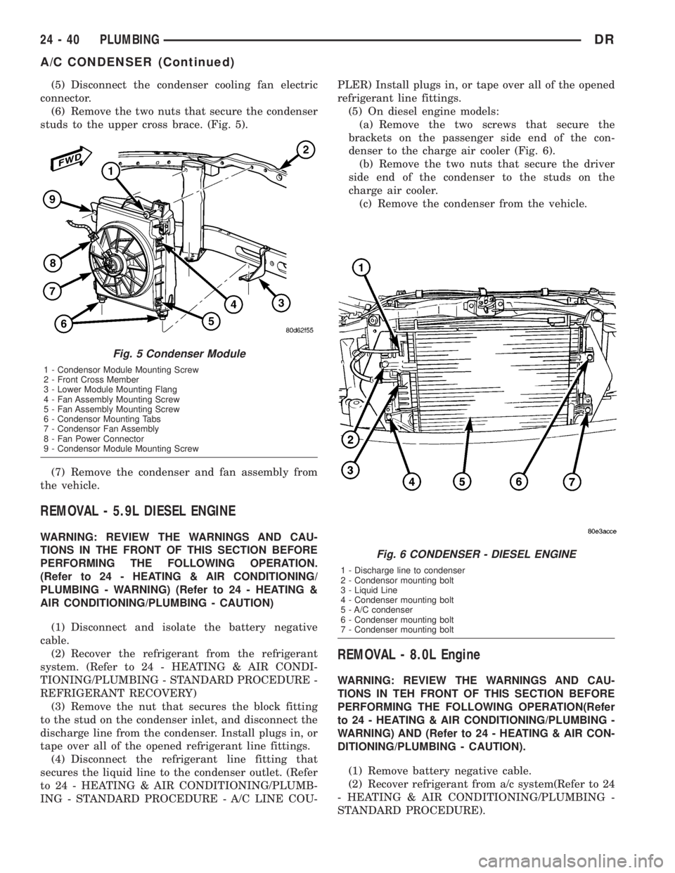
(5) Disconnect the condenser cooling fan electric
connector.
(6) Remove the two nuts that secure the condenser
studs to the upper cross brace. (Fig. 5).
(7) Remove the condenser and fan assembly from
the vehicle.
REMOVAL - 5.9L DIESEL ENGINE
WARNING: REVIEW THE WARNINGS AND CAU-
TIONS IN THE FRONT OF THIS SECTION BEFORE
PERFORMING THE FOLLOWING OPERATION.
(Refer to 24 - HEATING & AIR CONDITIONING/
PLUMBING - WARNING) (Refer to 24 - HEATING &
AIR CONDITIONING/PLUMBING - CAUTION)
(1) Disconnect and isolate the battery negative
cable.
(2) Recover the refrigerant from the refrigerant
system. (Refer to 24 - HEATING & AIR CONDI-
TIONING/PLUMBING - STANDARD PROCEDURE -
REFRIGERANT RECOVERY)
(3) Remove the nut that secures the block fitting
to the stud on the condenser inlet, and disconnect the
discharge line from the condenser. Install plugs in, or
tape over all of the opened refrigerant line fittings.
(4) Disconnect the refrigerant line fitting that
secures the liquid line to the condenser outlet. (Refer
to 24 - HEATING & AIR CONDITIONING/PLUMB-
ING - STANDARD PROCEDURE - A/C LINE COU-PLER) Install plugs in, or tape over all of the opened
refrigerant line fittings.
(5) On diesel engine models:
(a) Remove the two screws that secure the
brackets on the passenger side end of the con-
denser to the charge air cooler (Fig. 6).
(b) Remove the two nuts that secure the driver
side end of the condenser to the studs on the
charge air cooler.
(c) Remove the condenser from the vehicle.
REMOVAL - 8.0L Engine
WARNING: REVIEW THE WARNINGS AND CAU-
TIONS IN TEH FRONT OF THIS SECTION BEFORE
PERFORMING THE FOLLOWING OPERATION(Refer
to 24 - HEATING & AIR CONDITIONING/PLUMBING -
WARNING) AND (Refer to 24 - HEATING & AIR CON-
DITIONING/PLUMBING - CAUTION).
(1) Remove battery negative cable.
(2) Recover refrigerant from a/c system(Refer to 24
- HEATING & AIR CONDITIONING/PLUMBING -
STANDARD PROCEDURE).
Fig. 5 Condenser Module
1 - Condensor Module Mounting Screw
2 - Front Cross Member
3 - Lower Module Mounting Flang
4 - Fan Assembly Mounting Screw
5 - Fan Assembly Mounting Screw
6 - Condensor Mounting Tabs
7 - Condensor Fan Assembly
8 - Fan Power Connector
9 - Condensor Module Mounting Screw
Fig. 6 CONDENSER - DIESEL ENGINE
1 - Discharge line to condenser
2 - Condensor mounting bolt
3 - Liquid Line
4 - Condenser mounting bolt
5 - A/C condenser
6 - Condenser mounting bolt
7 - Condenser mounting bolt
24 - 40 PLUMBINGDR
A/C CONDENSER (Continued)
Page 2818 of 2895
NOTE: If the condenser is replaced, add 30 millili-
ters (1 fluid ounce) of refrigerant oil to the refriger-
ant system. Use only refrigerant oil of the type
recommended for the compressor in the vehicle(Re-
fer to 24 - HEATING & AIR CONDITIONING/PLUMB-
ING/REFRIGERANT OIL - DESCRIPTION).
(8) Charge the a/c system(Refer to 24 - HEATING
& AIR CONDITIONING/PLUMBING - STANDARD
PROCEDURE).
(9) Install the battery negative cable.
A/C CONDENSER FAN
REMOVAL - CONDENSER FAN (GAS ENGINE
ONLY - 3.7, 4.7 & 5.7L)
(1) Remove and isolate negative battery cable.
(2) Remove condenser assembly(Refer to 24 -
HEATING & AIR CONDITIONING/PLUMBING/A/C
CONDENSER - REMOVAL).
(3) Place condenser assembly on a flat work area
and remove screws holding fan assembly to con-
denser.
(4) Separate fan assembly from condenser noting
location of all seals for reinstallation.
INSTALLATION - CONDENSER FAN (GAS
ENGINE ONLY - 3.7, 4.7 & 5.7L)
(1) Position fan assembly on to the condenser.
(2) Check all fan shroud seals and replace as
required then install retainer screws to hold fan
assembly to condenser.
(3) Install condenser and fan assembly to vehi-
cle(Refer to 24 - HEATING & AIR CONDITIONING/
PLUMBING/A/C CONDENSER - INSTALLATION).
(4) Install battery negative cable.
A/C DISCHARGE LINE
REMOVAL
REMOVAL
WARNING: REVIEW THE WARNINGS AND CAU-
TIONS IN THE FRONT OF THIS SECTION BEFORE
PERFORMING THE FOLLOWING OPERATION.
(Refer to 24 - HEATING & AIR CONDITIONING/
PLUMBING - WARNING) (Refer to 24 - HEATING &
AIR CONDITIONING/PLUMBING - CAUTION)
(1) Disconnect and isolate the battery negative
cable.
(2) Recover the refrigerant from the refrigerant
system. (Refer to 24 - HEATING & AIR CONDI-TIONING/PLUMBING - STANDARD PROCEDURE -
REFRIGERANT RECOVERY)
(3) Unplug the wire harness connector from the
high pressure transducer.
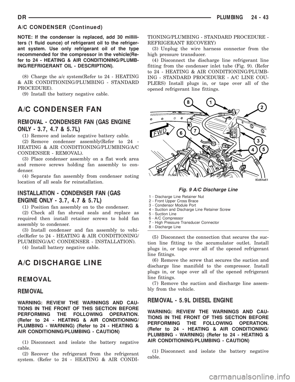
(4) Disconnect the discharge line refrigerant line
fitting from the condenser inlet tube (Fig. 9). (Refer
to 24 - HEATING & AIR CONDITIONING/PLUMB-
ING - STANDARD PROCEDURE - A/C LINE COU-
PLERS) Install plugs in, or tape over all of the
opened refrigerant line fittings.
(5) Disconnect the connection that secures the suc-
tion line fitting to the accumulator outlet. Install
plugs in, or tape over all of the opened refrigerant
line fittings.
(6) Remove the screw that secures the suction and
discharge line manifold to the compressor. Install
plugs in, or tape over all of the opened refrigerant
line fittings.
(7) Remove the suction and discharge line assem-
bly from the vehicle.REMOVAL - 5.9L DIESEL ENGINE
WARNING: REVIEW THE WARNINGS AND CAU-
TIONS IN THE FRONT OF THIS SECTION BEFORE
PERFORMING THE FOLLOWING OPERATION.
(Refer to 24 - HEATING & AIR CONDITIONING/
PLUMBING - WARNING) (Refer to 24 - HEATING &
AIR CONDITIONING/PLUMBING - CAUTION)
(1) Disconnect and isolate the battery negative
cable.
Fig. 9 A/C Discharge Line
1 - Discharge Line Retainer Nut
2 - Front Upper Cross Brace
3 - Condensor Module Port
4 - Suction and Discharge Line Retainer Screw
5 - Suction Line
6 - A/C Compressor
7 - High Pressure Transducer Connector
8 - Discharge Line
DRPLUMBING 24 - 43
A/C CONDENSER (Continued)
Page 2819 of 2895
(2) Recover the refrigerant from the refrigerant
system. (Refer to 24 - HEATING & AIR CONDI-
TIONING/PLUMBING - STANDARD PROCEDURE -
REFRIGERANT RECOVERY)
(3) Unplug the wire harness connector from the a/c
high pressure switch.
(4) Disconnect the suction line refrigerant line cou-
pler at the accumulator. (Refer to 24 - HEATING &
AIR CONDITIONING/PLUMBING - STANDARD
PROCEDURE - A/C LINE COUPLER) Install plugs
in, or tape over all of the opened refrigerant line fit-
tings.
(5) Remove the nut that secures the block fitting
to the stud on the condenser inlet and disconnect the
discharge line from the condenser. Install plugs in, or
tape over all of the opened refrigerant line fittings.
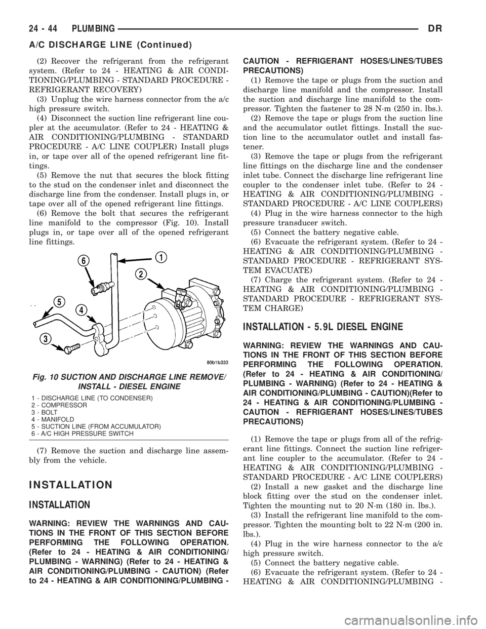
(6) Remove the bolt that secures the refrigerant
line manifold to the compressor (Fig. 10). Install
plugs in, or tape over all of the opened refrigerant
line fittings.
(7) Remove the suction and discharge line assem-
bly from the vehicle.
INSTALLATION
INSTALLATION
WARNING: REVIEW THE WARNINGS AND CAU-
TIONS IN THE FRONT OF THIS SECTION BEFORE
PERFORMING THE FOLLOWING OPERATION.
(Refer to 24 - HEATING & AIR CONDITIONING/
PLUMBING - WARNING) (Refer to 24 - HEATING &
AIR CONDITIONING/PLUMBING - CAUTION) (Refer
to 24 - HEATING & AIR CONDITIONING/PLUMBING -CAUTION - REFRIGERANT HOSES/LINES/TUBES
PRECAUTIONS)
(1) Remove the tape or plugs from the suction and
discharge line manifold and the compressor. Install
the suction and discharge line manifold to the com-
pressor. Tighten the fastener to 28 N´m (250 in. lbs.).
(2) Remove the tape or plugs from the suction line
and the accumulator outlet fittings. Install the suc-
tion line to the accumulator outlet and install fas-
tener.
(3) Remove the tape or plugs from the refrigerant
line fittings on the discharge line and the condenser
inlet tube. Connect the discharge line refrigerant line
coupler to the condenser inlet tube. (Refer to 24 -
HEATING & AIR CONDITIONING/PLUMBING -
STANDARD PROCEDURE - A/C LINE COUPLERS)
(4) Plug in the wire harness connector to the high
pressure transducer switch.
(5) Connect the battery negative cable.
(6) Evacuate the refrigerant system. (Refer to 24 -
HEATING & AIR CONDITIONING/PLUMBING -
STANDARD PROCEDURE - REFRIGERANT SYS-
TEM EVACUATE)
(7) Charge the refrigerant system. (Refer to 24 -
HEATING & AIR CONDITIONING/PLUMBING -
STANDARD PROCEDURE - REFRIGERANT SYS-
TEM CHARGE)
INSTALLATION - 5.9L DIESEL ENGINE
WARNING: REVIEW THE WARNINGS AND CAU-
TIONS IN THE FRONT OF THIS SECTION BEFORE
PERFORMING THE FOLLOWING OPERATION.
(Refer to 24 - HEATING & AIR CONDITIONING/
PLUMBING - WARNING) (Refer to 24 - HEATING &
AIR CONDITIONING/PLUMBING - CAUTION)(Refer to
24 - HEATING & AIR CONDITIONING/PLUMBING -
CAUTION - REFRIGERANT HOSES/LINES/TUBES
PRECAUTIONS)
(1) Remove the tape or plugs from all of the refrig-
erant line fittings. Connect the suction line refriger-
ant line coupler to the accumulator. (Refer to 24 -
HEATING & AIR CONDITIONING/PLUMBING -
STANDARD PROCEDURE - A/C LINE COUPLERS)
(2) Install a new gasket and the discharge line
block fitting over the stud on the condenser inlet.
Tighten the mounting nut to 20 N´m (180 in. lbs.).
(3) Install the refrigerant line manifold to the com-
pressor. Tighten the mounting bolt to 22 N´m (200 in.
lbs.).
(4) Plug in the wire harness connector to the a/c
high pressure switch.
(5) Connect the battery negative cable.
(6) Evacuate the refrigerant system. (Refer to 24 -
HEATING & AIR CONDITIONING/PLUMBING -
Fig. 10 SUCTION AND DISCHARGE LINE REMOVE/
INSTALL - DIESEL ENGINE
1 - DISCHARGE LINE (TO CONDENSER)
2 - COMPRESSOR
3 - BOLT
4 - MANIFOLD
5 - SUCTION LINE (FROM ACCUMULATOR)
6 - A/C HIGH PRESSURE SWITCH
24 - 44 PLUMBINGDR
A/C DISCHARGE LINE (Continued)
Page 2821 of 2895
STANDARD PROCEDURE - REFRIGERANT SYS-
TEM EVACUATE)
(8) Charge the refrigerant system. (Refer to 24 -
HEATING & AIR CONDITIONING/PLUMBING -
STANDARD PROCEDURE - REFRIGERANT SYS-
TEM CHARGE)
SUCTION LINE
REMOVAL
REMOVAL
WARNING: REVIEW THE WARNINGS AND CAU-
TIONS IN THE FRONT OF THIS SECTION BEFORE
PERFORMING THE FOLLOWING OPERATION.
(Refer to 24 - HEATING & AIR CONDITIONING/
PLUMBING - WARNING) (Refer to 24 - HEATING &
AIR CONDITIONING/PLUMBING - CAUTION)
(1) Disconnect and isolate the battery negative
cable.
(2) Recover the refrigerant from the refrigerant
system. (Refer to 24 - HEATING & AIR CONDI-
TIONING/PLUMBING - STANDARD PROCEDURE -
REFRIGERANT RECOVERY)
(3) Unplug the wire harness connector from the a/c
high pressure transducer.
(4) Disconnect the suction line refrigerant line cou-
pler at the accumulator. (Refer to 24 - HEATING &
AIR CONDITIONING/PLUMBING - STANDARD
PROCEDURE - A/C LINE COUPLER) Install plugs
in, or tape over all of the opened refrigerant line fit-
tings.
(5) Remove the nut that secures the condenser
inlet and disconnect the discharge line from the con-
denser. Install plugs in, or tape over all of the opened
refrigerant line fittings.
(6) Remove the suction and discharge line assem-
bly from the vehicle.
REMOVAL - 5.9L DIESEL ENGINE
WARNING: REVIEW THE WARNINGS AND CAU-
TIONS IN THE FRONT OF THIS SECTION BEFORE
PERFORMING THE FOLLOWING OPERATION.
(Refer to 24 - HEATING & AIR CONDITIONING/
PLUMBING - WARNING) (Refer to 24 - HEATING &
AIR CONDITIONING/PLUMBING - CAUTION)
(1) Disconnect and isolate the battery negative
cable.
(2) Recover the refrigerant from the refrigerant
system. (Refer to 24 - HEATING & AIR CONDI-TIONING/PLUMBING - STANDARD PROCEDURE -
REFRIGERANT RECOVERY)
(3) Unplug the wire harness connector from the a/c
high pressure switch.
(4) Disconnect the suction line refrigerant line cou-
pler at the accumulator. (Refer to 24 - HEATING &
AIR CONDITIONING/PLUMBING - STANDARD
PROCEDURE - A/C LINE COUPLER) Install plugs
in, or tape over all of the opened refrigerant line fit-
tings.
(5) Remove the nut that secures the block fitting
to the stud on the condenser inlet and disconnect the
discharge line from the condenser. Install plugs in, or
tape over all of the opened refrigerant line fittings.
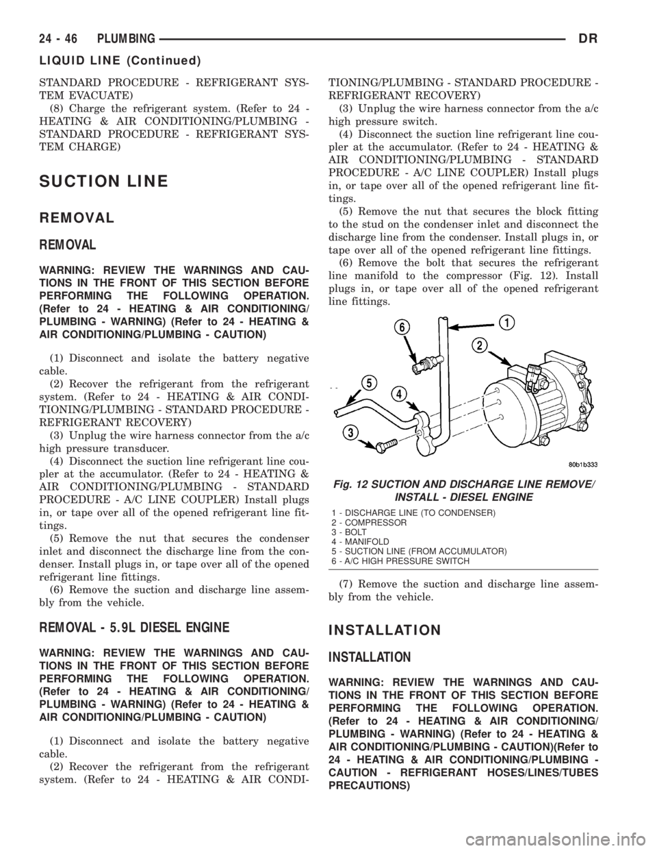
(6) Remove the bolt that secures the refrigerant
line manifold to the compressor (Fig. 12). Install
plugs in, or tape over all of the opened refrigerant
line fittings.
(7) Remove the suction and discharge line assem-
bly from the vehicle.
INSTALLATION
INSTALLATION
WARNING: REVIEW THE WARNINGS AND CAU-
TIONS IN THE FRONT OF THIS SECTION BEFORE
PERFORMING THE FOLLOWING OPERATION.
(Refer to 24 - HEATING & AIR CONDITIONING/
PLUMBING - WARNING) (Refer to 24 - HEATING &
AIR CONDITIONING/PLUMBING - CAUTION)(Refer to
24 - HEATING & AIR CONDITIONING/PLUMBING -
CAUTION - REFRIGERANT HOSES/LINES/TUBES
PRECAUTIONS)
Fig. 12 SUCTION AND DISCHARGE LINE REMOVE/
INSTALL - DIESEL ENGINE
1 - DISCHARGE LINE (TO CONDENSER)
2 - COMPRESSOR
3 - BOLT
4 - MANIFOLD
5 - SUCTION LINE (FROM ACCUMULATOR)
6 - A/C HIGH PRESSURE SWITCH
24 - 46 PLUMBINGDR
LIQUID LINE (Continued)