2003 DODGE RAM belt
[x] Cancel search: beltPage 427 of 2895
GENERATOR
DESCRIPTION
The generator is belt-driven by the engine using a
serpentine type drive belt. It is serviced only as a
complete assembly. If the generator fails for any rea-
son, the entire assembly must be replaced.
OPERATION
As the energized rotor begins to rotate within the
generator, the spinning magnetic field induces a cur-
rent into the windings of the stator coil. Once the
generator begins producing sufficient current, it also
provides the current needed to energize the rotor.
The stator winding connections deliver the induced
alternating current to 3 positive and 3 negative
diodes for rectification. From the diodes, rectified
direct current is delivered to the vehicle electrical
system through the generator battery terminal.
Although the generators appear the same exter-
nally, different generators with different output rat-
ings are used on this vehicle. Be certain that the
replacement generator has the same output rating
and part number as the original unit. Refer to Gen-
erator Ratings in the Specifications section at the
back of this group for amperage ratings and part
numbers.
Noise emitting from the generator may be caused
by: worn, loose or defective bearings; a loose or defec-
tive drive pulley; incorrect, worn, damaged or misad-
justed fan drive belt; loose mounting bolts; a
misaligned drive pulley or a defective stator or diode.
REMOVAL
3.7L / 4.7L
WARNING: DISCONNECT NEGATIVE CABLE FROM
BATTERY BEFORE REMOVING BATTERY OUTPUT
WIRE (B+ WIRE) FROM GENERATOR. FAILURE TO
DO SO CAN RESULT IN INJURY OR DAMAGE TO
ELECTRICAL SYSTEM.
(1) Disconnect negative battery cable at battery.
(2) Remove generator drive belt. Refer to 7, Cool-
ing System for procedure.
(3) Unsnap plastic insulator cap from B+ output
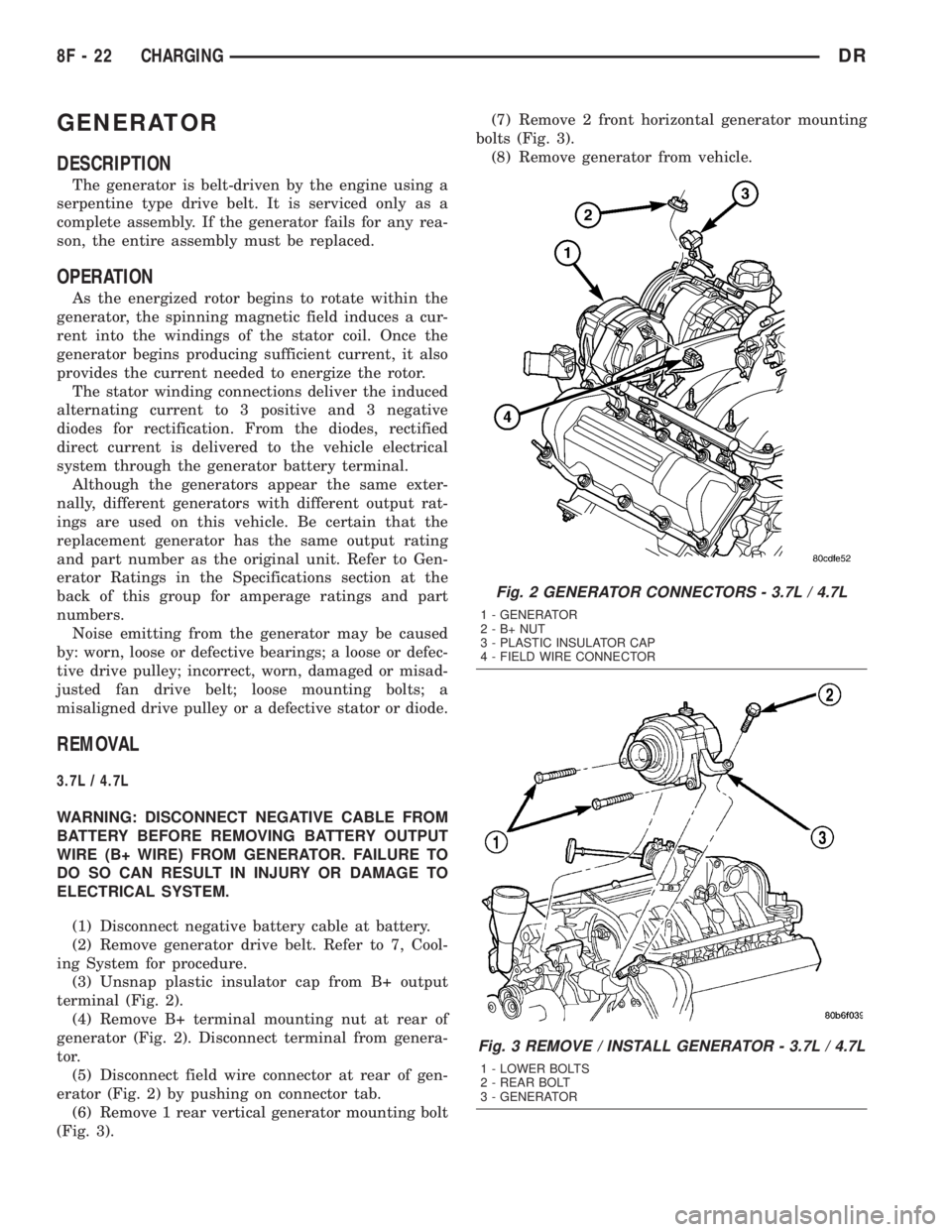
terminal (Fig. 2).
(4) Remove B+ terminal mounting nut at rear of
generator (Fig. 2). Disconnect terminal from genera-
tor.
(5) Disconnect field wire connector at rear of gen-
erator (Fig. 2) by pushing on connector tab.
(6) Remove 1 rear vertical generator mounting bolt
(Fig. 3).(7) Remove 2 front horizontal generator mounting
bolts (Fig. 3).
(8) Remove generator from vehicle.
Fig. 2 GENERATOR CONNECTORS - 3.7L / 4.7L
1 - GENERATOR
2-B+NUT
3 - PLASTIC INSULATOR CAP
4 - FIELD WIRE CONNECTOR
Fig. 3 REMOVE / INSTALL GENERATOR - 3.7L / 4.7L
1 - LOWER BOLTS
2 - REAR BOLT
3 - GENERATOR
8F - 22 CHARGINGDR
Page 428 of 2895
5.7L
WARNING: DISCONNECT NEGATIVE CABLE FROM
BATTERY BEFORE REMOVING BATTERY OUTPUT
WIRE (B+ WIRE) FROM GENERATOR. FAILURE TO
DO SO CAN RESULT IN INJURY OR DAMAGE TO
ELECTRICAL SYSTEM.
(1) Disconnect negative battery cable at battery.
(2) Remove generator drive belt. Refer to 7, Cool-
ing System for procedure.
(3) Unsnap plastic insulator cap from B+ output
terminal.
(4) Remove B+ terminal mounting nut at rear of
generator. Disconnect terminal from generator.
(5) Disconnect field wire connector at rear of gen-
erator by pushing on connector tab.
(6) Remove generator support bracket nuts and
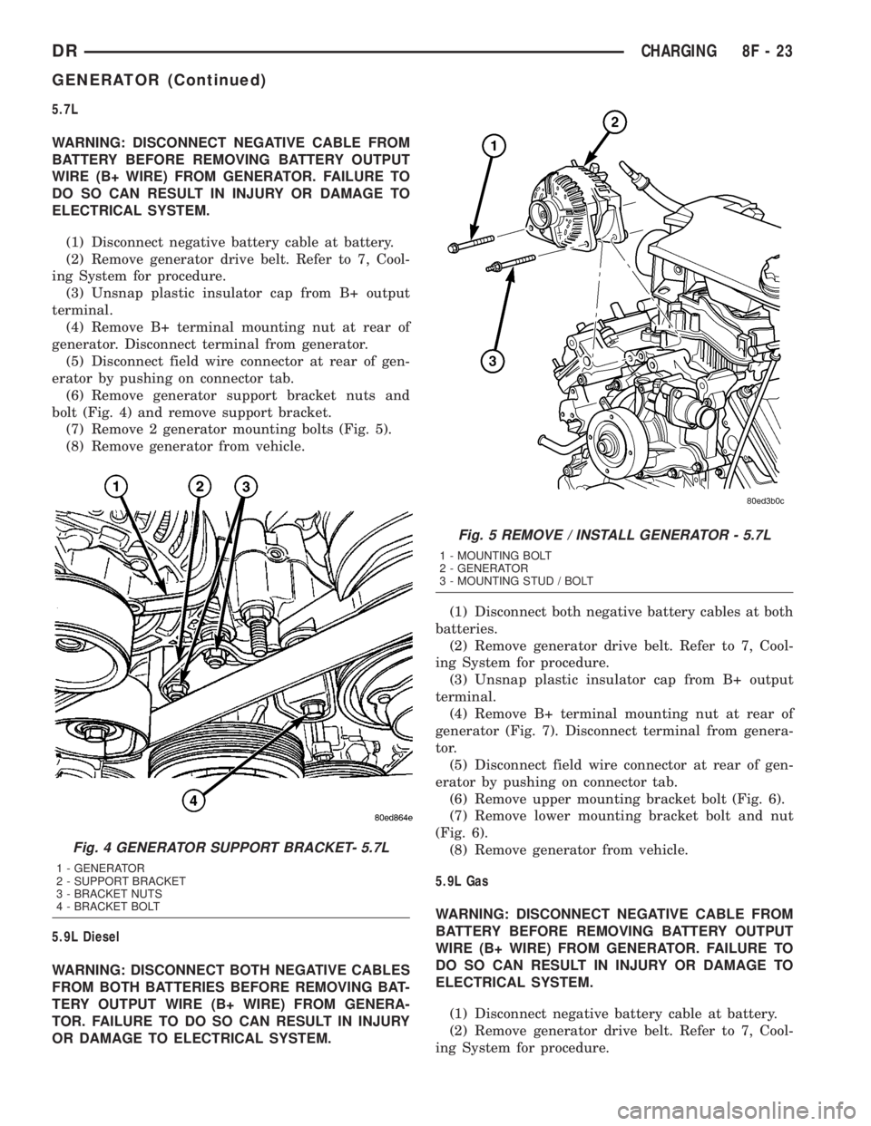
bolt (Fig. 4) and remove support bracket.
(7) Remove 2 generator mounting bolts (Fig. 5).
(8) Remove generator from vehicle.
5.9L Diesel
WARNING: DISCONNECT BOTH NEGATIVE CABLES
FROM BOTH BATTERIES BEFORE REMOVING BAT-
TERY OUTPUT WIRE (B+ WIRE) FROM GENERA-
TOR. FAILURE TO DO SO CAN RESULT IN INJURY
OR DAMAGE TO ELECTRICAL SYSTEM.(1) Disconnect both negative battery cables at both
batteries.
(2) Remove generator drive belt. Refer to 7, Cool-
ing System for procedure.
(3) Unsnap plastic insulator cap from B+ output
terminal.
(4) Remove B+ terminal mounting nut at rear of
generator (Fig. 7). Disconnect terminal from genera-
tor.
(5) Disconnect field wire connector at rear of gen-
erator by pushing on connector tab.
(6) Remove upper mounting bracket bolt (Fig. 6).
(7) Remove lower mounting bracket bolt and nut
(Fig. 6).
(8) Remove generator from vehicle.
5.9L Gas
WARNING: DISCONNECT NEGATIVE CABLE FROM
BATTERY BEFORE REMOVING BATTERY OUTPUT
WIRE (B+ WIRE) FROM GENERATOR. FAILURE TO
DO SO CAN RESULT IN INJURY OR DAMAGE TO
ELECTRICAL SYSTEM.
(1) Disconnect negative battery cable at battery.
(2) Remove generator drive belt. Refer to 7, Cool-
ing System for procedure.
Fig. 4 GENERATOR SUPPORT BRACKET- 5.7L
1 - GENERATOR
2 - SUPPORT BRACKET
3 - BRACKET NUTS
4 - BRACKET BOLT
Fig. 5 REMOVE / INSTALL GENERATOR - 5.7L
1 - MOUNTING BOLT
2 - GENERATOR
3 - MOUNTING STUD / BOLT
DRCHARGING 8F - 23
GENERATOR (Continued)
Page 429 of 2895
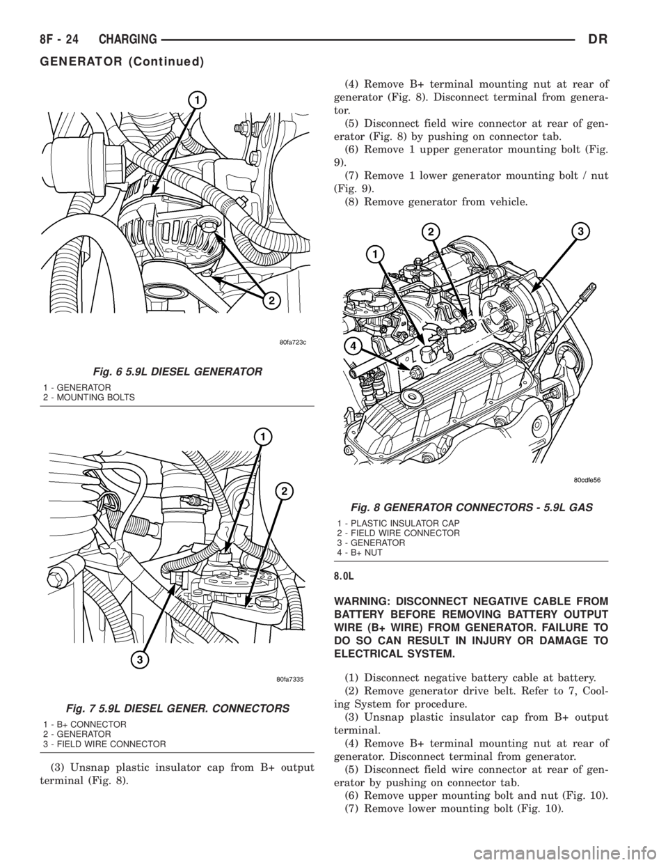
(3) Unsnap plastic insulator cap from B+ output
terminal (Fig. 8).(4) Remove B+ terminal mounting nut at rear of
generator (Fig. 8). Disconnect terminal from genera-
tor.
(5) Disconnect field wire connector at rear of gen-
erator (Fig. 8) by pushing on connector tab.
(6) Remove 1 upper generator mounting bolt (Fig.
9).
(7) Remove 1 lower generator mounting bolt / nut
(Fig. 9).
(8) Remove generator from vehicle.
8.0L
WARNING: DISCONNECT NEGATIVE CABLE FROM
BATTERY BEFORE REMOVING BATTERY OUTPUT
WIRE (B+ WIRE) FROM GENERATOR. FAILURE TO
DO SO CAN RESULT IN INJURY OR DAMAGE TO
ELECTRICAL SYSTEM.
(1) Disconnect negative battery cable at battery.
(2) Remove generator drive belt. Refer to 7, Cool-
ing System for procedure.
(3) Unsnap plastic insulator cap from B+ output
terminal.
(4) Remove B+ terminal mounting nut at rear of
generator. Disconnect terminal from generator.
(5) Disconnect field wire connector at rear of gen-
erator by pushing on connector tab.
(6) Remove upper mounting bolt and nut (Fig. 10).
(7) Remove lower mounting bolt (Fig. 10).
Fig. 6 5.9L DIESEL GENERATOR
1 - GENERATOR
2 - MOUNTING BOLTS
Fig. 7 5.9L DIESEL GENER. CONNECTORS
1 - B+ CONNECTOR
2 - GENERATOR
3 - FIELD WIRE CONNECTOR
Fig. 8 GENERATOR CONNECTORS - 5.9L GAS
1 - PLASTIC INSULATOR CAP
2 - FIELD WIRE CONNECTOR
3 - GENERATOR
4-B+NUT
8F - 24 CHARGINGDR
GENERATOR (Continued)
Page 430 of 2895
(8) Remove generator from vehicle.
INSTALLATION
3.7L / 4.7L
(1) Position generator to engine and install 2 hor-
izontal bolts and 1 vertical bolt.
(2) Tighten all 3 bolts. Refer to Torque Specifica-
tions.
(3) Snap field wire connector into rear of genera-
tor.
(4) Install B+ terminal eyelet to generator output
stud. Tighten mounting nut. Refer to Torque Specifi-
cations.
CAUTION: Never force a belt over a pulley rim
using a screwdriver. The synthetic fiber of the belt
can be damaged.
CAUTION: When installing a serpentine accessory
drive belt, the belt MUST be routed correctly. The
water pump may be rotating in the wrong direction
if the belt is installed incorrectly, causing the
engine to overheat. Refer to belt routing label in
engine compartment, or refer to Belt Schematics in
7, Cooling System.
(5) Install generator drive belt. Refer to 7, Cooling
System for procedure.
(6) Install negative battery cable to battery.
5.7L
(1) Position generator to engine and install 2
mounting bolts.
(2) Tighten bolts. Refer to Torque Specifications.
(3) Position support bracket to front of generator
and install bolt and nuts. Tighten bolt / nuts. Refer
to Torque Specifications.
(4) Snap field wire connector into rear of genera-
tor.
(5) Install B+ terminal eyelet to generator output
stud. Tighten mounting nut. Refer to Torque Specifi-
cations.
CAUTION: Never force a belt over a pulley rim
using a screwdriver. The synthetic fiber of the belt
can be damaged.
CAUTION: When installing a serpentine accessory
drive belt, the belt MUST be routed correctly. The
water pump may be rotating in the wrong direction
if the belt is installed incorrectly, causing the
engine to overheat. Refer to belt routing label in
engine compartment, or refer to Belt Schematics in
7, Cooling System.
(6) Install generator drive belt. Refer to 7, Cooling
System for procedure.
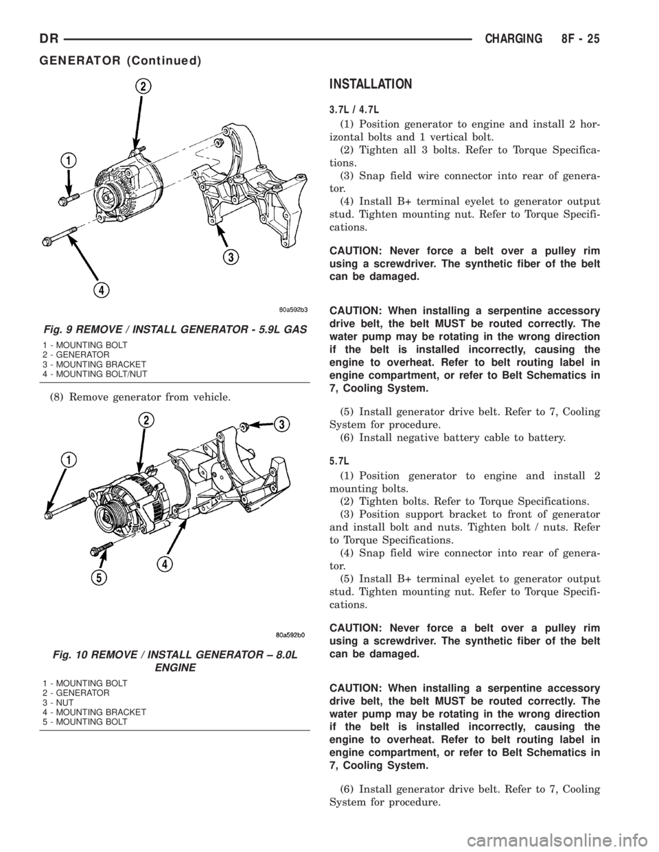
Fig. 9 REMOVE / INSTALL GENERATOR - 5.9L GAS
1 - MOUNTING BOLT
2 - GENERATOR
3 - MOUNTING BRACKET
4 - MOUNTING BOLT/NUT
Fig. 10 REMOVE / INSTALL GENERATOR ± 8.0L
ENGINE
1 - MOUNTING BOLT
2 - GENERATOR
3 - NUT
4 - MOUNTING BRACKET
5 - MOUNTING BOLT
DRCHARGING 8F - 25
GENERATOR (Continued)
Page 431 of 2895
(7) Install negative battery cable to battery.
5.9L Diesel
(1) Position generator to upper and lower mount-
ing brackets and install upper bolt and lower bolt /
nut.
(2) Tighten all bolts / nut. Refer to Torque Specifi-
cations.
(3) Snap field wire connector into rear of genera-
tor.
(4) Install B+ terminal eyelet to generator output
stud. Tighten mounting nut. Refer to Torque Specifi-
cations.
CAUTION: Never force a belt over a pulley rim
using a screwdriver. The synthetic fiber of the belt
can be damaged.
CAUTION: When installing a serpentine accessory
drive belt, the belt MUST be routed correctly. The
water pump may be rotating in the wrong direction
if the belt is installed incorrectly, causing the
engine to overheat. Refer to belt routing label in
engine compartment, or refer to Belt Schematics in
7, Cooling System.
(5) Install generator drive belt. Refer to 7, Cooling
System for procedure.
(6) Install both negative battery cables to both bat-
teries.
8.0L
(1) Position generator to engine and install lower
bolt and upper bolt / nut.
(2) Tighten all bolts / nut. Refer to Torque Specifi-
cations.
(3) Snap field wire connector into rear of genera-
tor.
(4) Install B+ terminal eyelet to generator output
stud. Tighten mounting nut. Refer to Torque Specifi-
cations.
CAUTION: Never force a belt over a pulley rim
using a screwdriver. The synthetic fiber of the belt
can be damaged.CAUTION: When installing a serpentine accessory
drive belt, the belt MUST be routed correctly. The
water pump may be rotating in the wrong direction
if the belt is installed incorrectly, causing the
engine to overheat. Refer to belt routing label in
engine compartment, or refer to Belt Schematics in
7, Cooling System.
(5) Install generator drive belt. Refer to 7, Cooling
System for procedure.
(6) Install negative battery cable to battery.
5.9L Gas
(1) Position generator to engine and install upper
bolt and lower bolt / nut.
(2) Tighten all bolts / nut. Refer to Torque Specifi-
cations.
(3) Snap field wire connector into rear of genera-
tor.
(4) Install B+ terminal eyelet to generator output
stud. Tighten mounting nut. Refer to Torque Specifi-
cations.
CAUTION: Never force a belt over a pulley rim
using a screwdriver. The synthetic fiber of the belt
can be damaged.
CAUTION: When installing a serpentine accessory
drive belt, the belt MUST be routed correctly. The
water pump may be rotating in the wrong direction
if the belt is installed incorrectly, causing the
engine to overheat. Refer to belt routing label in
engine compartment, or refer to Belt Schematics in
7, Cooling System.
(5) Install generator drive belt. Refer to 7, Cooling
System for procedure.
(6) Install negative battery cable to battery.
8F - 26 CHARGINGDR
GENERATOR (Continued)
Page 456 of 2895
HORN
TABLE OF CONTENTS
page page
HORN SYSTEM
DESCRIPTION..........................1
OPERATION............................1
DIAGNOSIS AND TESTING - HORN SYSTEM . . . 1
HORN
DIAGNOSIS AND TESTING - HORN..........1REMOVAL.............................2
INSTALLATION..........................2
HORN SWITCH
DESCRIPTION..........................2
DIAGNOSIS AND TESTING - HORN SWITCH . . . 2
HORN SYSTEM
DESCRIPTION
The dual-note horn system features dual electro-
magnetic horn units. The horn system includes the
following major components:
²Horn- The two horns are located on the left
side of the engine compartment below the Integrated
Power Module (IPM).
²Horn Switch- The horn switch is molded into
the driver airbag trim cover.
OPERATION
The horn system operates on battery current
received through a fuse in the Integrated Power
Module (IPM). The horn system circuit is designed so
that the system will remain operational, regardless
of the ignition switch position.
DIAGNOSIS AND TESTING - HORN SYSTEM
The most reliable, efficient, and accurate
means to diagnose the horn system requires the
use of a DRBIIItscan tool and the proper Diag-
nostic Procedures manual. The DRBIIItscan
tool can provide confirmation that the PCI data
bus is functional, that all of the electronic mod-
ules are sending and receiving the proper mes-
sages on the PCI data bus, and that the horns
are being sent the proper hard wired outputs
for them to perform their functions.
Refer to the appropriate wiring information. The
wiring information includes wiring diagrams, proper
wire and connector repair procedures, details of wire
harness routing and retention, connector pin-out
information and location views for the various wire
harness connectors, splices and grounds.
In most cases, any problem involving continually
sounding horns can be quickly alleviated by removing
the horn fuse from the Integrated Power Module
(IPM).WARNING: DISABLE THE AIRBAG SYSTEM
BEFORE ATTEMPTING ANY STEERING WHEEL,
STEERING COLUMN, SEAT BELT TENSIONER, SIDE
AIRBAG, OR INSTRUMENT PANEL COMPONENT
DIAGNOSIS OR SERVICE. DISCONNECT AND ISO-
LATE THE BATTERY NEGATIVE (GROUND) CABLE,
THEN WAIT TWO MINUTES FOR THE AIRBAG SYS-
TEM CAPACITOR TO DISCHARGE BEFORE PER-
FORMING FURTHER DIAGNOSIS OR SERVICE. THIS
IS THE ONLY SURE WAY TO DISABLE THE AIRBAG
SYSTEM. FAILURE TO TAKE THE PROPER PRE-
CAUTIONS COULD RESULT IN ACCIDENTAL AIR-
BAG DEPLOYMENT AND POSSIBLE PERSONAL
INJURY.
HORN
DIAGNOSIS AND TESTING - HORN
The most reliable, efficient, and accurate
means to diagnose the horn system requires the
use of a DRBIIItscan tool and the proper Diag-
nostic Procedures manual. The DRBIIItscan
tool can provide confirmation that the PCI data
bus is functional, that all of the electronic mod-
ules are sending and receiving the proper mes-
sages on the PCI data bus, and that the horns
are being sent the proper hard wired outputs
for them to perform their functions.
Refer to the appropriate wiring information. The
wiring information includes wiring diagrams, proper
wire and connector repair procedures, details of wire
harness routing and retention, connector pin-out
information and location views for the various wire
harness connectors, splices and grounds.
DRHORN 8H - 1
Page 457 of 2895
WARNING: DISABLE THE AIRBAG SYSTEM
BEFORE ATTEMPTING ANY STEERING WHEEL,
STEERING COLUMN, SEAT BELT TENSIONER, SIDE
AIRBAG, OR INSTRUMENT PANEL COMPONENT
DIAGNOSIS OR SERVICE. DISCONNECT AND ISO-
LATE THE BATTERY NEGATIVE (GROUND) CABLE,
THEN WAIT TWO MINUTES FOR THE AIRBAG SYS-
TEM CAPACITOR TO DISCHARGE BEFORE PER-
FORMING FURTHER DIAGNOSIS OR SERVICE. THIS
IS THE ONLY SURE WAY TO DISABLE THE AIRBAG
SYSTEM. FAILURE TO TAKE THE PROPER PRE-
CAUTIONS COULD RESULT IN ACCIDENTAL AIR-
BAG DEPLOYMENT AND POSSIBLE PERSONAL
INJURY.
REMOVAL
(1) Disconnect and isolate the battery negative
cable.
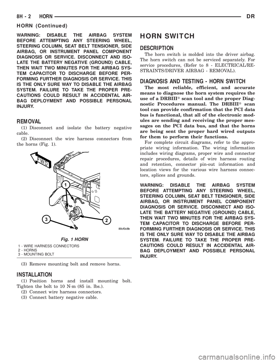
(2) Disconnect the wire harness connectors from
the horns (Fig. 1).
(3) Remove mounting bolt and remove horns.
INSTALLATION
(1) Position horns and install mounting bolt.
Tighten the bolt to 10 N´m (85 in. lbs.).
(2) Connect wire harness connectors.
(3) Connect battery negative cable.
HORN SWITCH
DESCRIPTION
The horn switch is molded into the driver airbag.
The horn switch can not be serviced separately. For
service procedures, (Refer to 8 - ELECTRICAL/RE-
STRAINTS/DRIVER AIRBAG - REMOVAL).
DIAGNOSIS AND TESTING - HORN SWITCH
The most reliable, efficient, and accurate
means to diagnose the horn system requires the
use of a DRBIIItscan tool and the proper Diag-
nostic Procedures manual. The DRBIIItscan
tool can provide confirmation that the PCI data
bus is functional, that all of the electronic mod-
ules are sending and receiving the proper mes-
sages on the PCI data bus, and that the horns
are being sent the proper hard wired outputs
for them to perform their functions.
For complete circuit diagrams, refer to the appro-
priate wiring information. The wiring information
includes wiring diagrams, proper wire and connector
repair procedures, details of wire harness routing
and retention, connector pin-out information and
location views for the various wire harness connec-
tors, splices and grounds.
WARNING: DISABLE THE AIRBAG SYSTEM
BEFORE ATTEMPTING ANY STEERING WHEEL,
STEERING COLUMN, SEAT BELT TENSIONER, SIDE
AIRBAG, OR INSTRUMENT PANEL COMPONENT
DIAGNOSIS OR SERVICE. DISCONNECT AND ISO-
LATE THE BATTERY NEGATIVE (GROUND) CABLE,
THEN WAIT TWO MINUTES FOR THE AIRBAG SYS-
TEM CAPACITOR TO DISCHARGE BEFORE PER-
FORMING FURTHER DIAGNOSIS OR SERVICE. THIS
IS THE ONLY SURE WAY TO DISABLE THE AIRBAG
SYSTEM. FAILURE TO TAKE THE PROPER PRE-
CAUTIONS COULD RESULT IN ACCIDENTAL AIR-
BAG DEPLOYMENT AND POSSIBLE PERSONAL
INJURY.
Fig. 1 HORN
1 - WIRE HARNESS CONNECTORS
2 - HORNS
3 - MOUNTING BOLT
8H - 2 HORNDR
HORN (Continued)
Page 475 of 2895

INSTALLATION
If engine has been cranked while distributor is
removed, establish the relationship between distribu-
tor shaft and number one piston position as follows:
Rotate crankshaft in a clockwise direction, as
viewed from front, until number one cylinder piston
is at top of compression stroke (compression should
be felt on finger with number one spark plug
removed). Then continue to slowly rotate engine
clockwise until indicating mark (Fig. 24) is aligned to
0 degree (TDC) mark on timing chain cover.
(1) Clean top of cylinder block for a good seal
between distributor base and block.
(2) Lightly oil the rubber o-ring seal on the distrib-
utor housing.
(3) Install rotor to distributor shaft.
(4) Position distributor into engine to its original
position. Engage tongue of distributor shaft with slot
in distributor oil pump drive gear. Position rotor to
the number one spark plug cable position.
(5) Install distributor holddown clamp and clamp
bolt. Do not tighten bolt at this time.
(6) Rotate the distributor housing until rotor is
aligned to CYL. NO. 1 alignment mark on the cam-
shaft position sensor (Fig. 25).
(7) Tighten clamp holddown bolt (Fig. 26) to 22.5
N´m (200 in. lbs.) torque.
(8) Connect camshaft position sensor wiring har-
ness to main engine harness.
(9) Install distributor cap. Tighten mounting
screws.
(10) Refer to the following, Checking Distributor
Position.
Checking Distributor Position
To verify correct distributor rotational position, the
DRB scan tool must be used.
WARNING: WHEN PERFORMING THE FOLLOWING
TEST, THE ENGINE WILL BE RUNNING. BE CARE-
FUL NOT TO STAND IN LINE WITH THE FAN
BLADES OR FAN BELT. DO NOT WEAR LOOSE
CLOTHING.
(1) Connect DRB scan tool to data link connector.
The data link connector is located in passenger com-
partment, below and to left of steering column.
(2) Gain access to SET SYNC screen on DRB.
(3) Follow directions on DRB screen and start
engine. Bring to operating temperature (engine must
be in ªclosed loopº mode).
(4) With engine running atidle speed, the words
IN RANGE should appear on screen along with 0É.
This indicates correct distributor position.(5) If a plus (+) or a minus (-) is displayed next to
degree number, and/or the degree displayed is not
zero, loosen but do not remove distributor holddown
clamp bolt. Rotate distributor until IN RANGE
appears on screen. Continue to rotate distributor
until achieving as close to 0É as possible. After
adjustment, tighten clamp bolt to 22.5 N´m (200 in.
lbs.) torque.
Do not attempt to adjust ignition timing using this
method. Rotating distributor will have no effect on
ignition timing. All ignition timing values are con-
trolled by Powertrain Control Module (PCM).
After testing, install air cleaner tubing.
DISTRIBUTOR CAP
DIAGNOSIS AND TESTING - DISTRIBUTOR
CAP - 5.9L V-8
Remove the distributor cap and wipe it clean with
a dry lint free cloth. Visually inspect the cap for
cracks, carbon paths, broken towers or damaged
rotor button (Fig. 27) or (Fig. 28). Also check for
white deposits on the inside (caused by condensation
entering the cap through cracks). Replace any cap
that displays charred or eroded terminals. The
machined surface of a terminal end (faces toward
rotor) will indicate some evidence of erosion from
normal operation. Examine the terminal ends for evi-
dence of mechanical interference with the rotor tip.
Fig. 27 CAP INSPECTIONÐEXTERNALÐTYPICAL
1 - BROKEN TOWER
2 - DISTRIBUTOR CAP
3 - CARBON PATH
4 - CRACK
8I - 18 IGNITION CONTROLDR
DISTRIBUTOR (Continued)