2003 DODGE RAM washer fluid
[x] Cancel search: washer fluidPage 1818 of 2895
(5) Coat the dust seal withhigh temp grease.
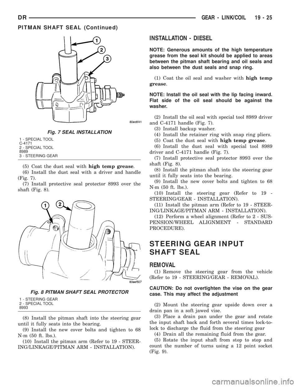
(6) Install the dust seal with a driver and handle
(Fig. 7).
(7) Install protective seal protector 8993 over the
shaft (Fig. 8).
(8) Install the pitman shaft into the steering gear
until it fully seats into the bearing.
(9) Install the new cover bolts and tighten to 68
N´m (50 ft. lbs.).
(10) Install the pitman arm (Refer to 19 - STEER-
ING/LINKAGE/PITMAN ARM - INSTALLATION).
INSTALLATION - DIESEL
NOTE: Generous amounts of the high temperature
grease from the seal kit should be applied to areas
between the pitman shaft bearing and oil seals and
also between the dust seals and snap ring.
(1) Coat the oil seal and washer withhigh temp
grease.
NOTE: Install the oil seal with the lip facing inward.
Flat side of the oil seal should be against the
washer.
(2) Install the oil seal with special tool 8989 driver
and C-4171 handle (Fig. 7).
(3) Install backup washer.
(4) Install the retainer ring with snap ring pliers.
(5) Coat the dust seal withhigh temp grease.
(6) Install the dust seal with special tool 8989
driver and C-4171 handle (Fig. 7).
(7) Install protective seal protector 8993 over the
shaft (Fig. 8).
(8) Install the pitman shaft into the steering gear
until it fully seats into the bearing.
(9) Install the new cover bolts and tighten to 68
N´m (50 ft. lbs.).
(10) Install the steering gear (Refer to 19 -
STEERING/GEAR - INSTALLATION).
(11) Install the pitman arm (Refer to 19 - STEER-
ING/LINKAGE/PITMAN ARM - INSTALLATION).
(12) Perform a wheel alignment (Refer to 2 - SUS-
PENSION/WHEEL ALIGNMENT - STANDARD
PROCEDURE).
STEERING GEAR INPUT
SHAFT SEAL
REMOVAL
(1) Remove the steering gear from the vehicle
(Refer to 19 - STEERING/GEAR - REMOVAL).
CAUTION: Do not overtighten the vise on the gear
case. This may affect the adjustment
(2) Mount the steering gear upside down over a
drain pan in a soft jawed vise.
(3) Place a drain pan under the gear and rotate
the input shaft back and forth several times lock-to-
lock to discharge the fluid from the steering gear
(4) Drain all the remaining fluid from the gear.
(5) Rotate the input shaft from stop to stop and
count the number of turns using a 12 point socket
(Fig. 9).
Fig. 7 SEAL INSTALLATION
1 - SPECIAL TOOL
C-4171
2 - SPECIAL TOOL
8989
3 - STEERING GEAR
Fig. 8 PITMAN SHAFT SEAL PROTECTOR
1 - STEERING GEAR
2 - SPECIAL TOOL
8993
DRGEAR - LINK/COIL 19 - 25
PITMAN SHAFT SEAL (Continued)
Page 1997 of 2895
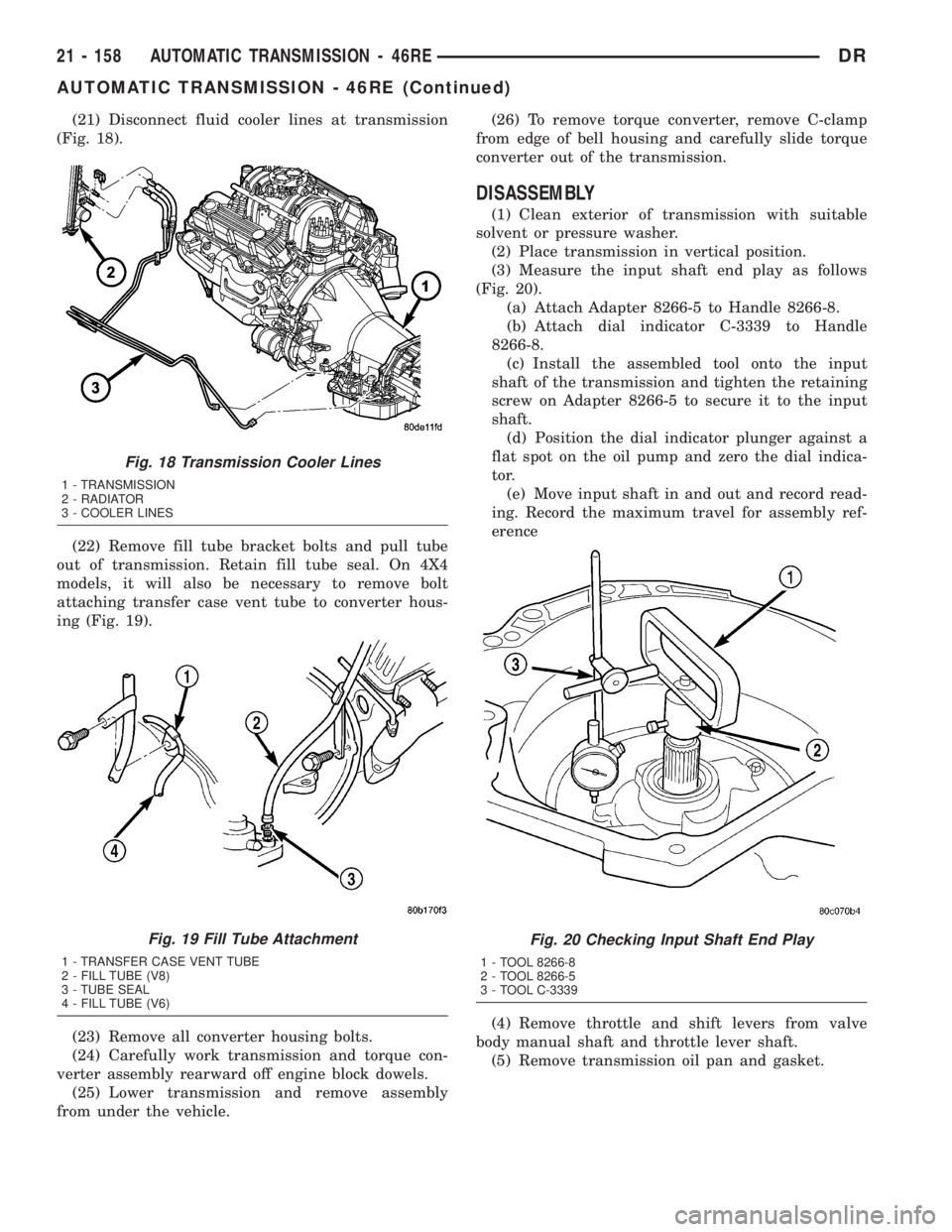
(21) Disconnect fluid cooler lines at transmission
(Fig. 18).
(22) Remove fill tube bracket bolts and pull tube
out of transmission. Retain fill tube seal. On 4X4
models, it will also be necessary to remove bolt
attaching transfer case vent tube to converter hous-
ing (Fig. 19).
(23) Remove all converter housing bolts.
(24) Carefully work transmission and torque con-
verter assembly rearward off engine block dowels.
(25) Lower transmission and remove assembly
from under the vehicle.(26) To remove torque converter, remove C-clamp
from edge of bell housing and carefully slide torque
converter out of the transmission.
DISASSEMBLY
(1) Clean exterior of transmission with suitable
solvent or pressure washer.
(2) Place transmission in vertical position.
(3) Measure the input shaft end play as follows
(Fig. 20).
(a) Attach Adapter 8266-5 to Handle 8266-8.
(b) Attach dial indicator C-3339 to Handle
8266-8.
(c) Install the assembled tool onto the input
shaft of the transmission and tighten the retaining
screw on Adapter 8266-5 to secure it to the input
shaft.
(d) Position the dial indicator plunger against a
flat spot on the oil pump and zero the dial indica-
tor.
(e) Move input shaft in and out and record read-
ing. Record the maximum travel for assembly ref-
erence
(4) Remove throttle and shift levers from valve
body manual shaft and throttle lever shaft.
(5) Remove transmission oil pan and gasket.
Fig. 18 Transmission Cooler Lines
1 - TRANSMISSION
2 - RADIATOR
3 - COOLER LINES
Fig. 19 Fill Tube Attachment
1 - TRANSFER CASE VENT TUBE
2 - FILL TUBE (V8)
3 - TUBE SEAL
4 - FILL TUBE (V6)
Fig. 20 Checking Input Shaft End Play
1 - TOOL 8266-8
2 - TOOL 8266-5
3 - TOOL C-3339
21 - 158 AUTOMATIC TRANSMISSION - 46REDR
AUTOMATIC TRANSMISSION - 46RE (Continued)
Page 2004 of 2895
NOTE: Do not use shop towels or rags to dry the
case (or any other transmission component) unless
they are made from lint-free materials. Lint will stick
to case surfaces and transmission components and
circulate throughout the transmission after assem-
bly. A sufficient quantity of lint can block fluid pas-
sages and interfere with valve body operation.
Lubricate transmission parts with MopartATF +4,
Automatic Transmission fluid during overhaul and
assembly. Use petroleum jelly to prelubricate seals,
O-rings, and thrust washers. Petroleum jelly can also
be used to hold parts in place during reassembly.
INSPECTION
Inspect the case for cracks, porous spots, worn
bores, or damaged threads. Damaged threads can be
repaired with Helicoil thread inserts. However, the
case will have to be replaced if it exhibits any type of
damage or wear.
Lubricate the front band adjusting screw threads
with petroleum jelly and thread the screw part-way
into the case. Be sure the screw turns freely.
Inspect the transmission bushings during overhaul.
Bushing condition is important as worn, scored bush-
ings contribute to low pressures, clutch slip and
accelerated wear of other components. However, do
not replace bushings as a matter of course. Replace
bushings only when they are actually worn, or
scored.
Use recommended tools to replace bushings. The
tools are sized and designed to remove, install, and
seat bushings correctly. The bushing replacement
tools are included in Bushing Tool Set C-3887-B.Pre-sized service bushings are available for
replacement purposes. Only the sun gear bushings
are not serviced.
The use of crocus cloth is permissible where neces-
sary, providing it is used carefully. When used on
shafts, or valves, use extreme care to avoid rounding
off sharp edges. Sharp edges are vital as they pre-
vent foreign matter from getting between the valve
and valve bore.
Do not reuse oil seals, gaskets, seal rings, or
O-rings during overhaul. Replace these parts as a
matter of course. Also do not reuse snap rings or
E-clips that are bent or distorted. Replace these parts
as well.
ASSEMBLY
Do not allow dirt, grease, or foreign material to
enter the case or transmission components during
assembly. Keep the transmission case and compo-
nents clean. Also make sure the tools and workbench
area used for reassembly operations are equally
clean.
Shop towels used for wiping off tools and your
hands must be made fromlint freematerials. Lint
will stick to transmission parts and could interfere
with valve operation or even restrict fluid passages.
Lubricate transmission clutch and gear compo-
nents with MopartATF +4, Automatic Transmission
fluid, during reassembly. Soak clutch discs in trans-
mission fluid before installation.
Use MopartDoor Ease, or Ru-GlydeŸ on piston
seals and O-rings to ease installation. Petroleum jelly
can also be used to lubricate and hold thrust washers
and plates in position during assembly.
Do not use chassis grease, bearing grease,
white grease, or similar lubricants on any part.
These types of lubricants can eventually block or
restrict fluid passages and valve operation. Use
petroleum jelly only.
Do not force parts into place. The transmission
components and sub-assemblies are easily installed
by hand when properly aligned. If a part seems dif-
ficult to install, it is either misaligned or incorrectly
assembled. Verify that thrust washers, thrust plates
and seal rings are correctly positioned.
The planetary geartrain, front/rear clutch assem-
blies and oil pump are all much easier to install
when the transmission case is upright. Either tilt the
case upward with wood blocks, or cut a hole in the
bench large enough for the intermediate shaft and
rear support. Then lower the shaft and support into
the hole and support the rear of the case directly on
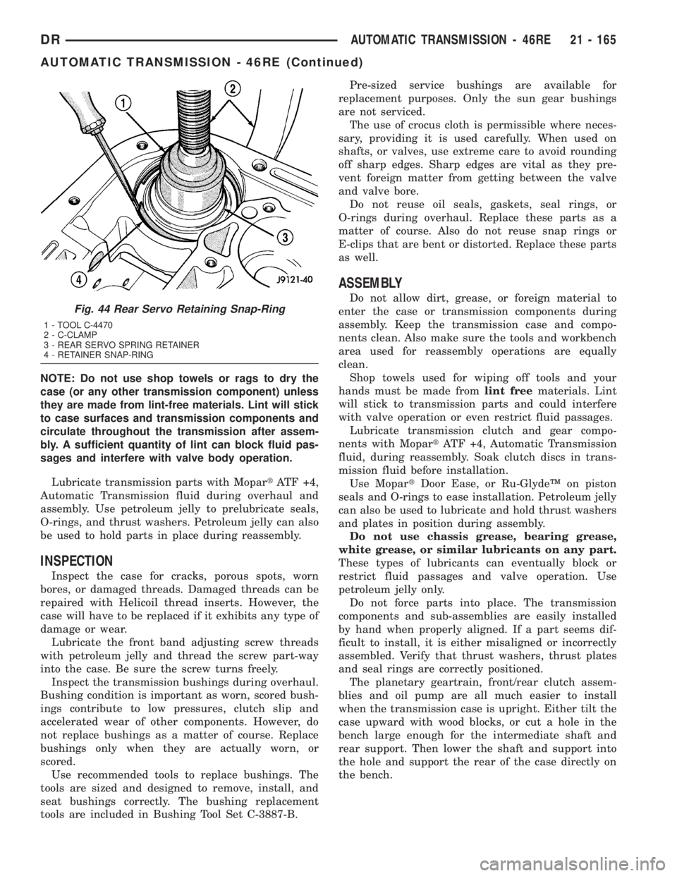
the bench.Fig. 44 Rear Servo Retaining Snap-Ring
1 - TOOL C-4470
2 - C-CLAMP
3 - REAR SERVO SPRING RETAINER
4 - RETAINER SNAP-RING
DRAUTOMATIC TRANSMISSION - 46RE 21 - 165
AUTOMATIC TRANSMISSION - 46RE (Continued)
Page 2009 of 2895
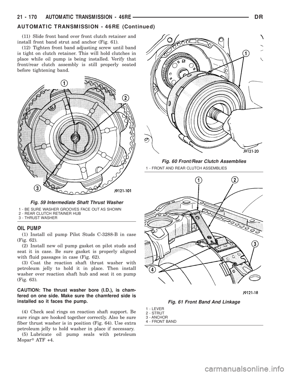
(11) Slide front band over front clutch retainer and
install front band strut and anchor (Fig. 61).
(12) Tighten front band adjusting screw until band
is tight on clutch retainer. This will hold clutches in
place while oil pump is being installed. Verify that
front/rear clutch assembly is still properly seated
before tightening band.
OIL PUMP
(1) Install oil pump Pilot Studs C-3288-B in case
(Fig. 62).
(2) Install new oil pump gasket on pilot studs and
seat it in case. Be sure gasket is properly aligned
with fluid passages in case (Fig. 62).
(3) Coat the reaction shaft thrust washer with
petroleum jelly to hold it in place. Then install
washer over reaction shaft hub and seat it on pump
(Fig. 63).
CAUTION: The thrust washer bore (I.D.), is cham-
fered on one side. Make sure the chamfered side is
installed so it faces the pump.
(4) Check seal rings on reaction shaft support. Be
sure rings are hooked together correctly. Also be sure
fiber thrust washer is in position (Fig. 64). Use extra
petroleum jelly to hold washer in place if necessary.
(5) Lubricate oil pump seals with petroleum
MopartATF +4.
Fig. 59 Intermediate Shaft Thrust Washer
1 - BE SURE WASHER GROOVES FACE OUT AS SHOWN
2 - REAR CLUTCH RETAINER HUB
3 - THRUST WASHER
Fig. 60 Front/Rear Clutch Assemblies
1 - FRONT AND REAR CLUTCH ASSEMBLIES
Fig. 61 Front Band And Linkage
1 - LEVER
2 - STRUT
3 - ANCHOR
4 - FRONT BAND
21 - 170 AUTOMATIC TRANSMISSION - 46REDR
AUTOMATIC TRANSMISSION - 46RE (Continued)
Page 2026 of 2895
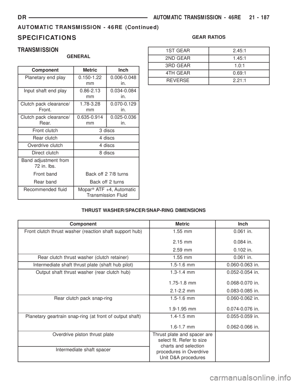
SPECIFICATIONS
TRANSMISSION
GENERAL
Component Metric Inch
Planetary end play 0.150-1.22
mm0.006-0.048
in.
Input shaft end play 0.86-2.13
mm0.034-0.084
in.
Clutch pack clearance/
Front.1.78-3.28
mm0.070-0.129
in.
Clutch pack clearance/
Rear.0.635-0.914
mm0.025-0.036
in.
Front clutch 3 discs
Rear clutch 4 discs
Overdrive clutch 4 discs
Direct clutch 8 discs
Band adjustment from
72 in. lbs.
Front band Back off 2 7/8 turns
Rear band Back off 2 turns
Recommended fluid MoparTATF +4, Automatic
Transmission FluidGEAR RATIOS
1ST GEAR 2.45:1
2ND GEAR 1.45:1
3RD GEAR 1.0:1
4TH GEAR 0.69:1
REVERSE 2.21:1
THRUST WASHER/SPACER/SNAP-RING DIMENSIONS
Component Metric Inch
Front clutch thrust washer (reaction shaft support hub) 1.55 mm 0.061 in.
2.15 mm 0.084 in.
2.59 mm 0.102 in.
Rear clutch thrust washer (clutch retainer) 1.55 mm 0.061 in.
Intermediate shaft thrust plate (shaft hub pilot) 1.5-1.6 mm 0.060-0.063 in.
Output shaft thrust washer (rear clutch hub) 1.3-1.4 mm 0.052-0.054 in.
1.75-1.8 mm 0.068-0.070 in.
2.1-2.2 mm 0.083-0.085 in.
Rear clutch pack snap-ring 1.5-1.6 mm 0.060-0.062 in.
1.9-1.95 mm 0.074-0.076 in.
Planetary geartrain snap-ring (at front of output shaft) 1.4-1.5 mm 0.055-0.059 in.
1.6-1.7 mm 0.062-0.066 in.
Overdrive piston thrust plate Thrust plate and spacer are
select fit. Refer to size
charts and selection
procedures in Overdrive
Unit D&A procedures Intermediate shaft spacer
DRAUTOMATIC TRANSMISSION - 46RE 21 - 187
AUTOMATIC TRANSMISSION - 46RE (Continued)
Page 2051 of 2895
OIL PUMP
DESCRIPTION
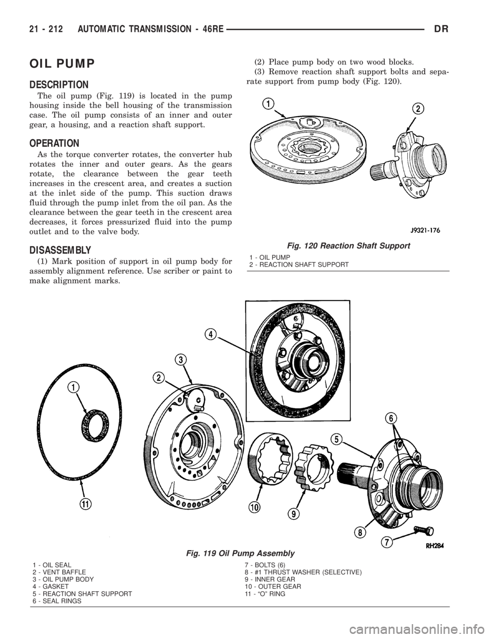
The oil pump (Fig. 119) is located in the pump
housing inside the bell housing of the transmission
case. The oil pump consists of an inner and outer
gear, a housing, and a reaction shaft support.
OPERATION
As the torque converter rotates, the converter hub
rotates the inner and outer gears. As the gears
rotate, the clearance between the gear teeth
increases in the crescent area, and creates a suction
at the inlet side of the pump. This suction draws
fluid through the pump inlet from the oil pan. As the
clearance between the gear teeth in the crescent area
decreases, it forces pressurized fluid into the pump
outlet and to the valve body.
DISASSEMBLY
(1) Mark position of support in oil pump body for
assembly alignment reference. Use scriber or paint to
make alignment marks.(2) Place pump body on two wood blocks.
(3) Remove reaction shaft support bolts and sepa-
rate support from pump body (Fig. 120).
Fig. 119 Oil Pump Assembly
1 - OIL SEAL 7 - BOLTS (6)
2 - VENT BAFFLE 8 - #1 THRUST WASHER (SELECTIVE)
3 - OIL PUMP BODY 9 - INNER GEAR
4 - GASKET 10 - OUTER GEAR
5 - REACTION SHAFT SUPPORT 11 - ªOº RING
6 - SEAL RINGS
Fig. 120 Reaction Shaft Support
1 - OIL PUMP
2 - REACTION SHAFT SUPPORT
21 - 212 AUTOMATIC TRANSMISSION - 46REDR
Page 2055 of 2895
REACTION SHAFT SUPPORT BUSHING
(1) Place reaction shaft support upright on a clean,
smooth surface.
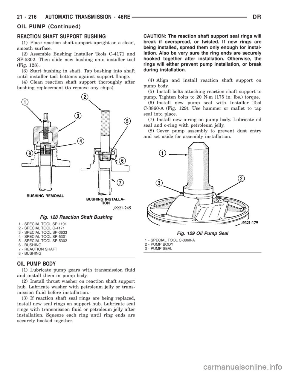
(2) Assemble Bushing Installer Tools C-4171 and
SP-5302. Then slide new bushing onto installer tool
(Fig. 128).
(3) Start bushing in shaft. Tap bushing into shaft
until installer tool bottoms against support flange.
(4) Clean reaction shaft support thoroughly after
bushing replacement (to remove any chips).
OIL PUMP BODY
(1) Lubricate pump gears with transmission fluid
and install them in pump body.
(2) Install thrust washer on reaction shaft support
hub. Lubricate washer with petroleum jelly or trans-
mission fluid before installation.
(3) If reaction shaft seal rings are being replaced,
install new seal rings on support hub. Lubricate seal
rings with transmission fluid or petroleum jelly after
installation. Squeeze each ring until ring ends are
securely hooked together.CAUTION: The reaction shaft support seal rings will
break if overspread, or twisted. If new rings are
being installed, spread them only enough for instal-
lation. Also be very sure the ring ends are securely
hooked together after installation. Otherwise, the
rings will either prevent pump installation, or break
during installation.
(4) Align and install reaction shaft support on
pump body.
(5) Install bolts attaching reaction shaft support to
pump. Tighten bolts to 20 N´m (175 in. lbs.) torque.
(6) Install new pump seal with Installer Tool
C-3860-A (Fig. 129). Use hammer or mallet to tap
seal into place.
(7) Install new o-ring on pump body. Lubricate oil
seal and o-ring with petroleum jelly.
(8) Cover pump assembly to prevent dust entry
and set aside for assembly installation.
Fig. 128 Reaction Shaft Bushing
1 - SPECIAL TOOL SP-1191
2 - SPECIAL TOOL C-4171
3 - SPECIAL TOOL SP-3633
4 - SPECIAL TOOL SP-5301
5 - SPECIAL TOOL SP-5302
6 - BUSHING
7 - REACTION SHAFT
8 - BUSHING
Fig. 129 Oil Pump Seal
1 - SPECIAL TOOL C-3860-A
2 - PUMP BODY
3 - PUMP SEAL
21 - 216 AUTOMATIC TRANSMISSION - 46REDR
OIL PUMP (Continued)
Page 2084 of 2895
INSPECTION
Inspect the planetary gear sets and annulus gears.
The planetary pinions, shafts, washers, and retaining
pins are serviceable. However, if a pinion carrier is
damaged, the entire planetary gear set must be
replaced as an assembly.
Replace the annulus gears if the teeth are chipped,
broken, or worn, or the gear is cracked. Replace the
planetary thrust plates and the tabbed thrust wash-
ers if cracked, scored or worn.
Inspect the machined surfaces of the intermediate
shaft. Be sure the oil passages are open and clear.
Replace the shaft if scored, pitted, or damaged.
Inspect the sun gear and driving shell. If either
component is worn or damaged, remove the sun gear
rear retaining ring and separate the sun gear and
thrust plate from the driving shell. Then replace the
necessary component.
Replace the sun gear as an assembly if the gear
teeth are chipped or worn. Also replace the gear as
an assembly if the bushings are scored or worn. The
sun gear bushings are not serviceable. Replace the
thrust plate if worn, or severely scored. Replace the
driving shell if distorted, cracked, or damaged in any
way.
Replace all snap-rings during geartrain assembly.
Reusing snap-rings is not recommended.
ASSEMBLY
(1) Lubricate sun gear and planetary gears with
transmission fluid during assembly. Use petroleum
jelly to lubricate intermediate shaft bushing surfaces,
thrust washers and thrust plates and to hold these
parts in place during assembly.
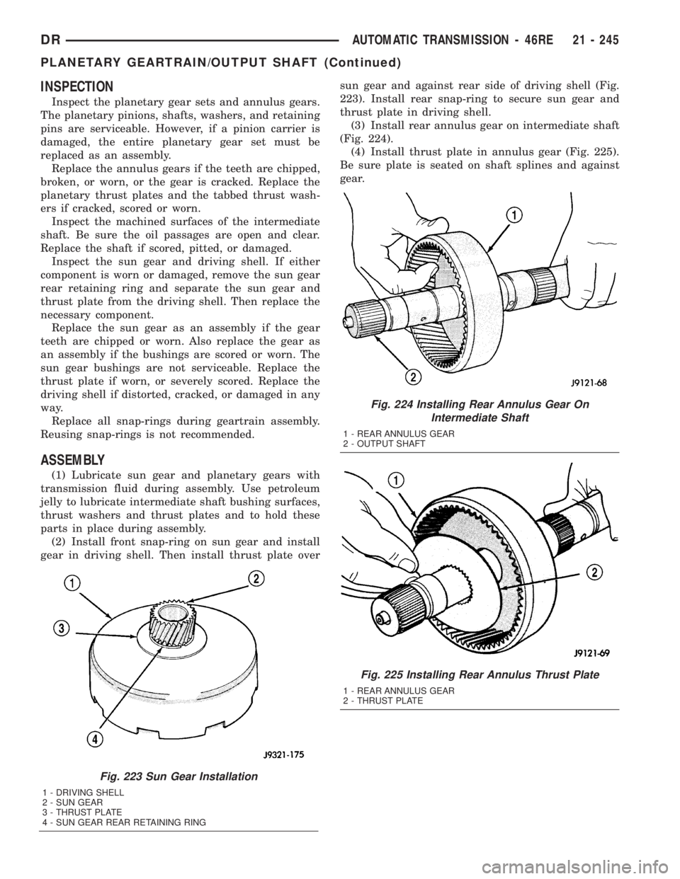
(2) Install front snap-ring on sun gear and install
gear in driving shell. Then install thrust plate oversun gear and against rear side of driving shell (Fig.
223). Install rear snap-ring to secure sun gear and
thrust plate in driving shell.
(3) Install rear annulus gear on intermediate shaft
(Fig. 224).
(4) Install thrust plate in annulus gear (Fig. 225).
Be sure plate is seated on shaft splines and against
gear.
Fig. 223 Sun Gear Installation
1 - DRIVING SHELL
2 - SUN GEAR
3 - THRUST PLATE
4 - SUN GEAR REAR RETAINING RING
Fig. 224 Installing Rear Annulus Gear On
Intermediate Shaft
1 - REAR ANNULUS GEAR
2 - OUTPUT SHAFT
Fig. 225 Installing Rear Annulus Thrust Plate
1 - REAR ANNULUS GEAR
2 - THRUST PLATE
DRAUTOMATIC TRANSMISSION - 46RE 21 - 245
PLANETARY GEARTRAIN/OUTPUT SHAFT (Continued)