2003 DODGE RAM lubrication
[x] Cancel search: lubricationPage 1285 of 2895
(12) Remove cylinder head cover retaining bolts.
(13) Remove cylinder head cover.
INSTALLATION
CAUTION: Do not use harsh cleaners to clean the
cylinder head covers. Severe damage to covers
may occur.
NOTE: The gasket may be used again, provided no
cuts, tears, or deformation has occurred.
(1) Clean cylinder head cover and both sealing sur-
faces. Inspect and replace gasket as necessary.
(2) Tighten cylinder head cover bolts and double
ended studs to 12 N´m (105 in. lbs).
(3) Install right rear breather tube and filter
assembly.
(4) Connect injector, ignition coil electrical connec-
tors and harness retaining clips.
(5) Install the oil fill tube.
(6) Install PCV hose.
(7) Install heater hoses.
(8) Install air conditioning compressor retaining
bolts.
(9) Install accessory drive belt(Refer to 7 - COOL-
ING/ACCESSORY DRIVE/DRIVE BELTS - INSTAL-
LATION).
(10) Fill Cooling system(Refer to 7 - COOLING -
STANDARD PROCEDURE).
(11) Install air cleaner assembly, resonator assem-
bly and air inlet hose.
(12) Connect battery negative cable.
ROCKER ARM
DESCRIPTION
The rocker arms are steel stampings with an inte-
gral roller bearing. The rocker arms incorporate a 2.8
mm (0.11 inch) oil hole in the lash adjuster socket for
roller and camshaft lubrication.
REMOVAL
NOTE: Disconnect the battery negative cable to pre-
vent accidental starter engagement.
(1) Remove the cylinder head cover (Refer to 9 -
ENGINE/CYLINDER HEAD/CYLINDER HEAD
COVER(S) - REMOVAL).
(2) For rocker arm removal on cylinder #4, Rotate
the crankshaft until cylinder #1 is at BDC intake
stroke.(3) For rocker arm removal on cylinder #1, Rotate
the crankshaft until cylinder #1 is at BDC combus-
tion stroke.
(4) For rocker arm removal on cylinders #3 and #5,
Rotate the crankshaft until cylinder #1 is at TDC
exhaust stroke.
(5) For rocker arm removal on cylinders #2 and #6,
Rotate the crankshaft until cylinder #1 is at TDC
ignition stroke.
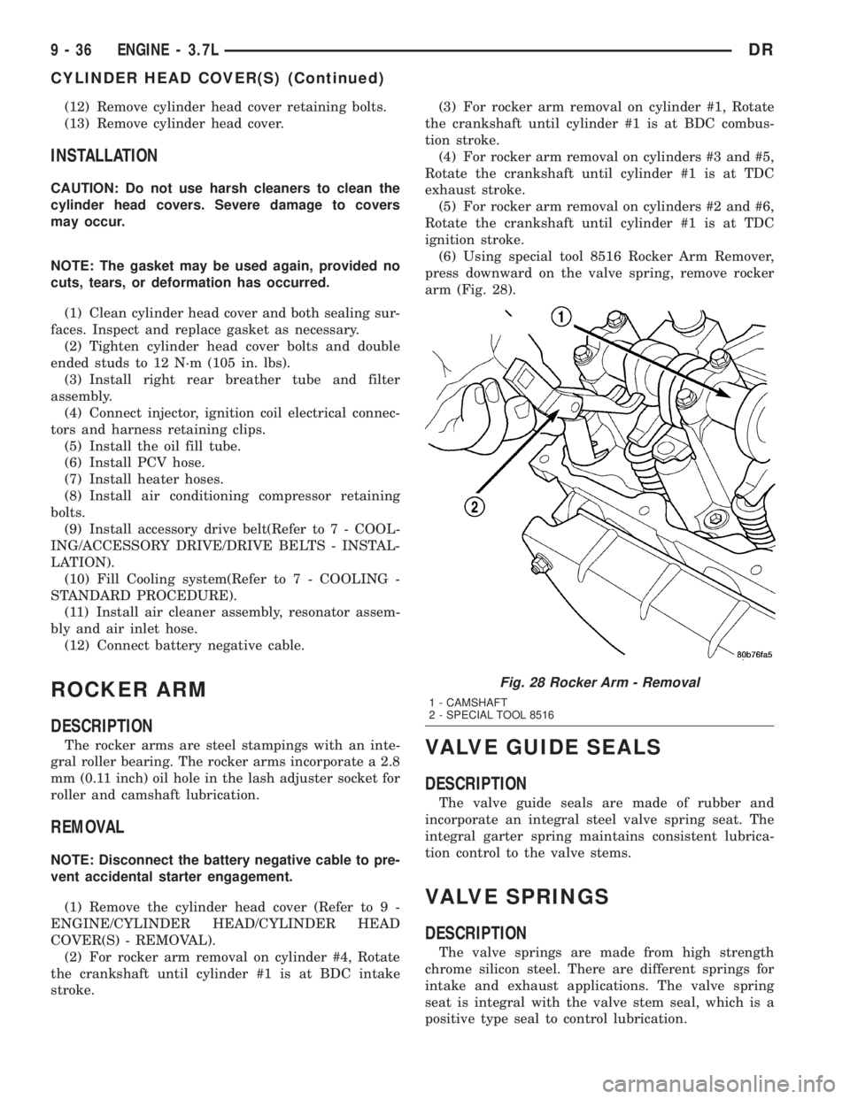
(6) Using special tool 8516 Rocker Arm Remover,
press downward on the valve spring, remove rocker
arm (Fig. 28).
VALVE GUIDE SEALS
DESCRIPTION
The valve guide seals are made of rubber and
incorporate an integral steel valve spring seat. The
integral garter spring maintains consistent lubrica-
tion control to the valve stems.
VALVE SPRINGS
DESCRIPTION
The valve springs are made from high strength
chrome silicon steel. There are different springs for
intake and exhaust applications. The valve spring
seat is integral with the valve stem seal, which is a
positive type seal to control lubrication.
Fig. 28 Rocker Arm - Removal
1 - CAMSHAFT
2 - SPECIAL TOOL 8516
9 - 36 ENGINE - 3.7LDR
CYLINDER HEAD COVER(S) (Continued)
Page 1288 of 2895
(4) Determine taper by subtracting the smaller
diameter from the larger diameter.
(5) Rotate measuring device 90É and repeat steps
above.
(6) Determine out-of-roundness by comparing the
difference between each measurement.
(7) If cylinder bore taper does not exceed 0.025
mm (0.001 inch) and out-of-roundness does not
exceed 0.025 mm (0.001 inch), the cylinder bore can
be honed. If the cylinder bore taper or out- of-round
condition exceeds these maximum limits, the cylinder
block must be replaced. A slight amount of taper
always exists in the cylinder bore after the engine
has been in use for a period of time.
CRANKSHAFT
DESCRIPTION
The crankshaft is constructed of nodular cast iron.
The crankshaft is a three throw split pin design with
six counterweights for balancing purposes. The
crankshaft is supported by four select fit main bear-
ings with the number two serving as the thrust
washer location. The main journals of the crankshaft
are cross drilled to improve rod bearing lubrication.
The number six counterweight has provisions for
crankshaft position sensor target wheel mounting.
The select fit main bearing markings are located on
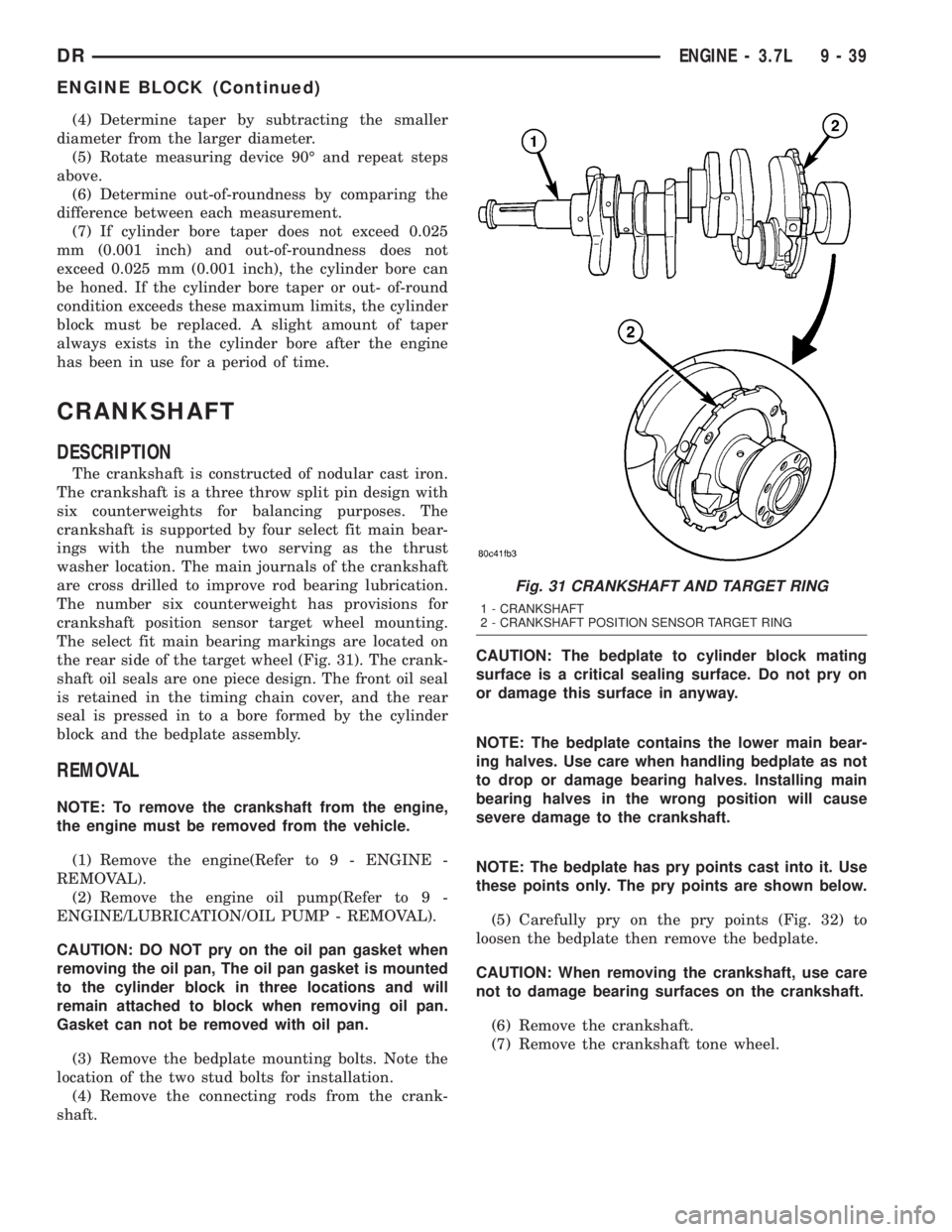
the rear side of the target wheel (Fig. 31). The crank-
shaft oil seals are one piece design. The front oil seal
is retained in the timing chain cover, and the rear
seal is pressed in to a bore formed by the cylinder
block and the bedplate assembly.
REMOVAL
NOTE: To remove the crankshaft from the engine,
the engine must be removed from the vehicle.
(1) Remove the engine(Refer to 9 - ENGINE -
REMOVAL).
(2) Remove the engine oil pump(Refer to 9 -
ENGINE/LUBRICATION/OIL PUMP - REMOVAL).
CAUTION: DO NOT pry on the oil pan gasket when
removing the oil pan, The oil pan gasket is mounted
to the cylinder block in three locations and will
remain attached to block when removing oil pan.
Gasket can not be removed with oil pan.
(3) Remove the bedplate mounting bolts. Note the
location of the two stud bolts for installation.
(4) Remove the connecting rods from the crank-
shaft.CAUTION: The bedplate to cylinder block mating
surface is a critical sealing surface. Do not pry on
or damage this surface in anyway.
NOTE: The bedplate contains the lower main bear-
ing halves. Use care when handling bedplate as not
to drop or damage bearing halves. Installing main
bearing halves in the wrong position will cause
severe damage to the crankshaft.
NOTE: The bedplate has pry points cast into it. Use
these points only. The pry points are shown below.
(5) Carefully pry on the pry points (Fig. 32) to
loosen the bedplate then remove the bedplate.
CAUTION: When removing the crankshaft, use care
not to damage bearing surfaces on the crankshaft.
(6) Remove the crankshaft.
(7) Remove the crankshaft tone wheel.
Fig. 31 CRANKSHAFT AND TARGET RING
1 - CRANKSHAFT
2 - CRANKSHAFT POSITION SENSOR TARGET RING
DRENGINE - 3.7L 9 - 39
ENGINE BLOCK (Continued)
Page 1297 of 2895
STANDARD PROCEDURE
CONNECTING ROD BEARING FITTING
Inspect the connecting rod bearings for scoring.
Check the bearings for normal wear patterns, scor-
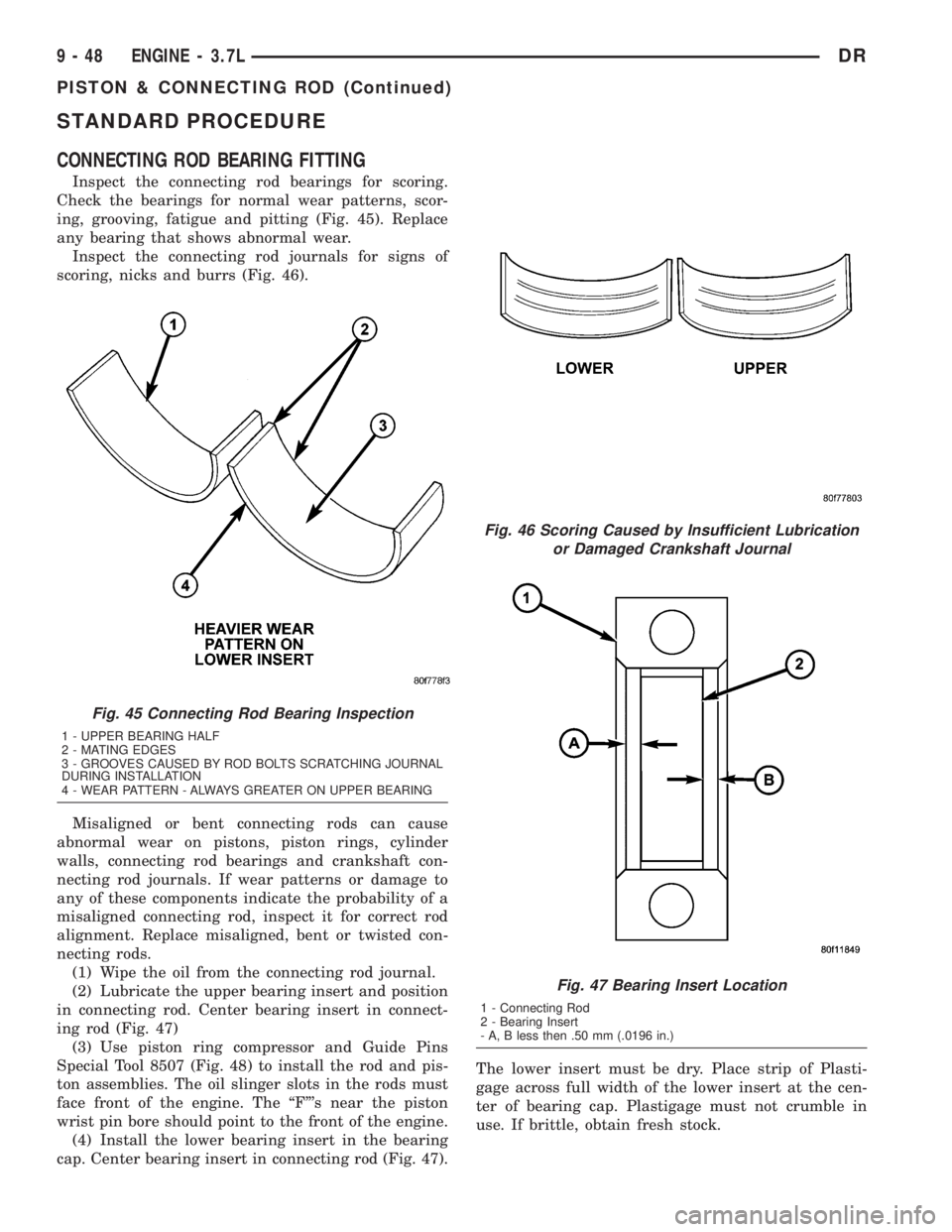
ing, grooving, fatigue and pitting (Fig. 45). Replace
any bearing that shows abnormal wear.
Inspect the connecting rod journals for signs of
scoring, nicks and burrs (Fig. 46).
Misaligned or bent connecting rods can cause
abnormal wear on pistons, piston rings, cylinder
walls, connecting rod bearings and crankshaft con-
necting rod journals. If wear patterns or damage to
any of these components indicate the probability of a
misaligned connecting rod, inspect it for correct rod
alignment. Replace misaligned, bent or twisted con-
necting rods.
(1) Wipe the oil from the connecting rod journal.
(2) Lubricate the upper bearing insert and position
in connecting rod. Center bearing insert in connect-
ing rod (Fig. 47)
(3) Use piston ring compressor and Guide Pins
Special Tool 8507 (Fig. 48) to install the rod and pis-
ton assemblies. The oil slinger slots in the rods must
face front of the engine. The ªFº's near the piston
wrist pin bore should point to the front of the engine.
(4) Install the lower bearing insert in the bearing
cap. Center bearing insert in connecting rod (Fig. 47).The lower insert must be dry. Place strip of Plasti-
gage across full width of the lower insert at the cen-
ter of bearing cap. Plastigage must not crumble in
use. If brittle, obtain fresh stock.
Fig. 45 Connecting Rod Bearing Inspection
1 - UPPER BEARING HALF
2 - MATING EDGES
3 - GROOVES CAUSED BY ROD BOLTS SCRATCHING JOURNAL
DURING INSTALLATION
4 - WEAR PATTERN - ALWAYS GREATER ON UPPER BEARING
Fig. 46 Scoring Caused by Insufficient Lubrication
or Damaged Crankshaft Journal
Fig. 47 Bearing Insert Location
1 - Connecting Rod
2 - Bearing Insert
- A, B less then .50 mm (.0196 in.)
9 - 48 ENGINE - 3.7LDR
PISTON & CONNECTING ROD (Continued)
Page 1299 of 2895
Slide snug-fitting feeler gauge between the con-
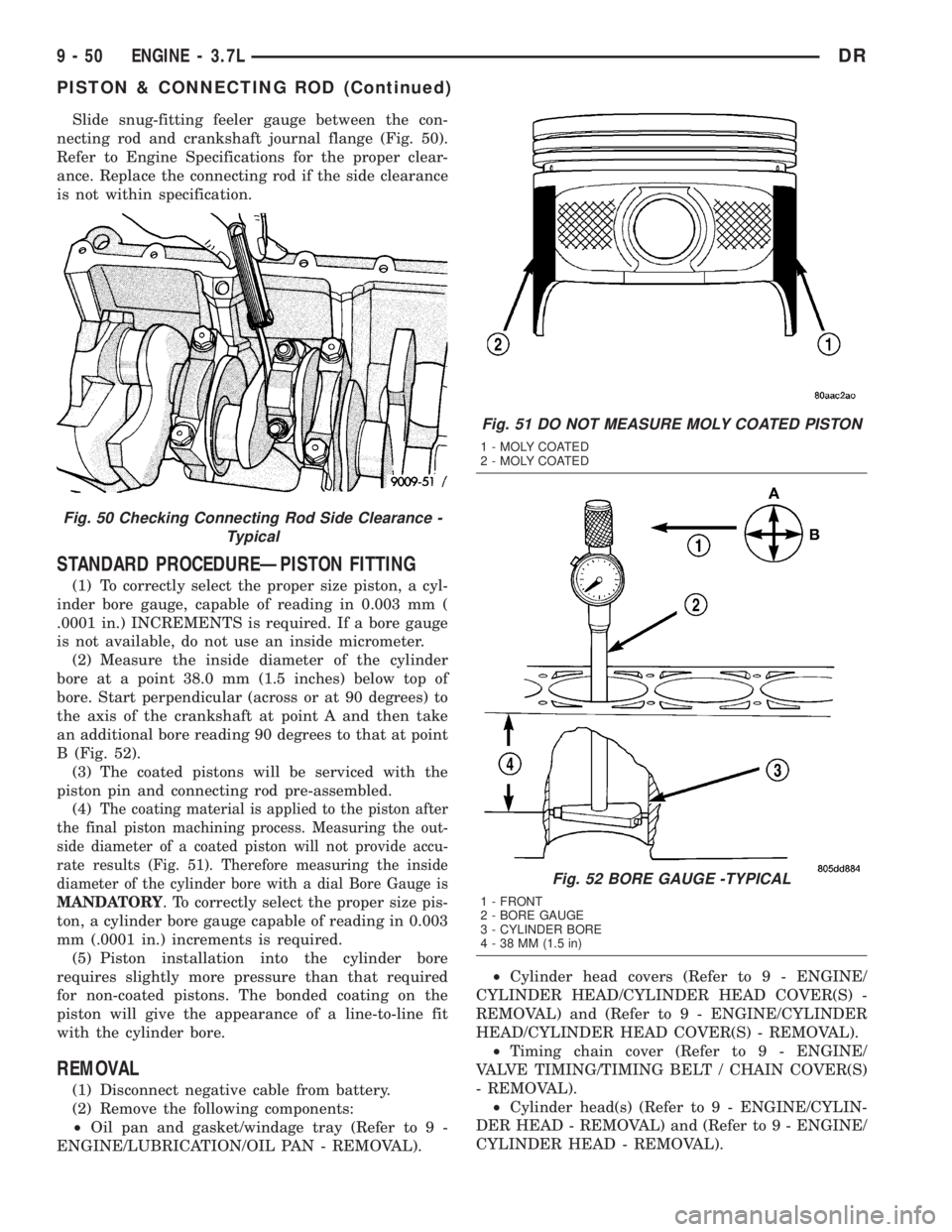
necting rod and crankshaft journal flange (Fig. 50).
Refer to Engine Specifications for the proper clear-
ance. Replace the connecting rod if the side clearance
is not within specification.
STANDARD PROCEDUREÐPISTON FITTING
(1) To correctly select the proper size piston, a cyl-
inder bore gauge, capable of reading in 0.003 mm (
.0001 in.) INCREMENTS is required. If a bore gauge
is not available, do not use an inside micrometer.
(2) Measure the inside diameter of the cylinder
bore at a point 38.0 mm (1.5 inches) below top of
bore. Start perpendicular (across or at 90 degrees) to
the axis of the crankshaft at point A and then take
an additional bore reading 90 degrees to that at point
B (Fig. 52).
(3) The coated pistons will be serviced with the
piston pin and connecting rod pre-assembled.
(4)
The coating material is applied to the piston after
the final piston machining process. Measuring the out-
side diameter of a coated piston will not provide accu-
rate results (Fig. 51). Therefore measuring the inside
diameter of the cylinder bore with a dial Bore Gauge is
MANDATORY
. To correctly select the proper size pis-
ton, a cylinder bore gauge capable of reading in 0.003
mm (.0001 in.) increments is required.
(5) Piston installation into the cylinder bore
requires slightly more pressure than that required
for non-coated pistons. The bonded coating on the
piston will give the appearance of a line-to-line fit
with the cylinder bore.
REMOVAL
(1) Disconnect negative cable from battery.
(2) Remove the following components:
²Oil pan and gasket/windage tray (Refer to 9 -
ENGINE/LUBRICATION/OIL PAN - REMOVAL).²Cylinder head covers (Refer to 9 - ENGINE/
CYLINDER HEAD/CYLINDER HEAD COVER(S) -
REMOVAL) and (Refer to 9 - ENGINE/CYLINDER
HEAD/CYLINDER HEAD COVER(S) - REMOVAL).
²Timing chain cover (Refer to 9 - ENGINE/
VALVE TIMING/TIMING BELT / CHAIN COVER(S)
- REMOVAL).
²Cylinder head(s) (Refer to 9 - ENGINE/CYLIN-
DER HEAD - REMOVAL) and (Refer to 9 - ENGINE/
CYLINDER HEAD - REMOVAL).
Fig. 50 Checking Connecting Rod Side Clearance -
Typical
Fig. 51 DO NOT MEASURE MOLY COATED PISTON
1 - MOLY COATED
2 - MOLY COATED
Fig. 52 BORE GAUGE -TYPICAL
1 - FRONT
2 - BORE GAUGE
3 - CYLINDER BORE
4 - 38 MM (1.5 in)
9 - 50 ENGINE - 3.7LDR
PISTON & CONNECTING ROD (Continued)
Page 1301 of 2895
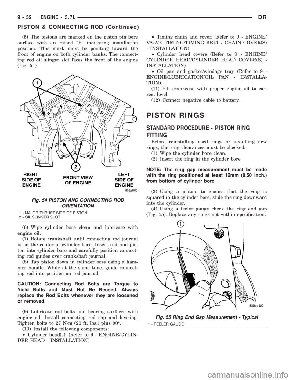
(5) The pistons are marked on the piston pin bore
surface with an raised ªFº indicating installation
position. This mark must be pointing toward the
front of engine on both cylinder banks. The connect-
ing rod oil slinger slot faces the front of the engine
(Fig. 54).
(6) Wipe cylinder bore clean and lubricate with
engine oil.
(7) Rotate crankshaft until connecting rod journal
is on the center of cylinder bore. Insert rod and pis-
ton into cylinder bore and carefully position connect-
ing rod guides over crankshaft journal.
(8) Tap piston down in cylinder bore using a ham-
mer handle. While at the same time, guide connect-
ing rod into position on rod journal.
CAUTION: Connecting Rod Bolts are Torque to
Yield Bolts and Must Not Be Reused. Always
replace the Rod Bolts whenever they are loosened
or removed.
(9) Lubricate rod bolts and bearing surfaces with
engine oil. Install connecting rod cap and bearing.
Tighten bolts to 27 N´m (20 ft. lbs.) plus 90É.
(10) Install the following components:
²Cylinder head(s). (Refer to 9 - ENGINE/CYLIN-
DER HEAD - INSTALLATION).²Timing chain and cover. (Refer to 9 - ENGINE/
VALVE TIMING/TIMING BELT / CHAIN COVER(S)
- INSTALLATION).
²Cylinder head covers (Refer to 9 - ENGINE/
CYLINDER HEAD/CYLINDER HEAD COVER(S) -
INSTALLATION).
²Oil pan and gasket/windage tray. (Refer to 9 -
ENGINE/LUBRICATION/OIL PAN - INSTALLA-
TION).
(11) Fill crankcase with proper engine oil to cor-
rect level.
(12) Connect negative cable to battery.
PISTON RINGS
STANDARD PROCEDURE - PISTON RING
FITTING
Before reinstalling used rings or installing new
rings, the ring clearances must be checked.
(1) Wipe the cylinder bore clean.
(2) Insert the ring in the cylinder bore.
NOTE: The ring gap measurement must be made
with the ring positioned at least 12mm (0.50 inch.)
from bottom of cylinder bore.
(3) Using a piston, to ensure that the ring is
squared in the cylinder bore, slide the ring downward
into the cylinder.
(4) Using a feeler gauge check the ring end gap
(Fig. 55). Replace any rings not within specification.
Fig. 54 PISTON AND CONNECTING ROD
ORIENTATION
1 - MAJOR THRUST SIDE OF PISTON
2 - OIL SLINGER SLOT
Fig. 55 Ring End Gap Measurement - Typical
1 - FEELER GAUGE
9 - 52 ENGINE - 3.7LDR
PISTON & CONNECTING ROD (Continued)
Page 1309 of 2895
REAR MOUNT
REMOVAL
(1) Raise the vehicle on a hoist.
(2) Using a suitable jack, support transmission.
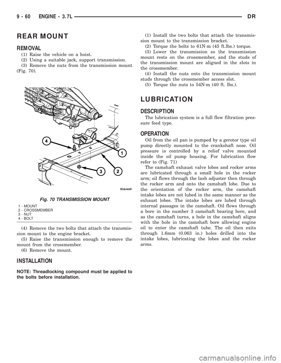
(3) Remove the nuts from the transmission mount
(Fig. 70).
(4) Remove the two bolts that attach the transmis-
sion mount to the engine bracket.
(5) Raise the transmission enough to remove the
mount from the crossmember.
(6) Remove the mount.
INSTALLATION
NOTE: Threadlocking compound must be applied to
the bolts before installation.(1) Install the two bolts that attach the transmis-
sion mount to the transmission bracket.
(2) Torque the bolts to 61N´m (45 ft.lbs.) torque.
(3) Lower the transmission so the transmission
mount rests on the crossmember, and the studs of
the transmission mount are aligned in the slots in
the crossmember.
(4) Install the nuts onto the transmission mount
studs through the crossmember access slot.
(5) Torque the nuts to 54N´m (40 ft. lbs.).
LUBRICATION
DESCRIPTION
The lubrication system is a full flow filtration pres-
sure feed type.
OPERATION
Oil from the oil pan is pumped by a gerotor type oil
pump directly mounted to the crankshaft nose. Oil
pressure is controlled by a relief valve mounted
inside the oil pump housing. For lubrication flow
refer to (Fig. 71)
The camshaft exhaust valve lobes and rocker arms
are lubricated through a small hole in the rocker
arm; oil flows through the lash adjuster then through
the rocker arm and onto the camshaft lobe. Due to
the orientation of the rocker arm, the camshaft
intake lobes are not lubed in the same manner as the
exhaust lobes. The intake lobes are lubed through
internal passages in the camshaft. Oil flows through
a bore in the number 3 camshaft bearing bore, and
as the camshaft turns, a hole in the camshaft aligns
with the hole in the camshaft bore allowing engine
oil to enter the camshaft tube. The oil then exits
through 1.6mm (0.063 in.) holes drilled into the
intake lobes, lubricating the lobes and the rocker
arms.
Fig. 70 TRANSMISSION MOUNT
1 - MOUNT
2 - CROSSMEMBER
3 - NUT
4 - BOLT
9 - 60 ENGINE - 3.7LDR
Page 1310 of 2895
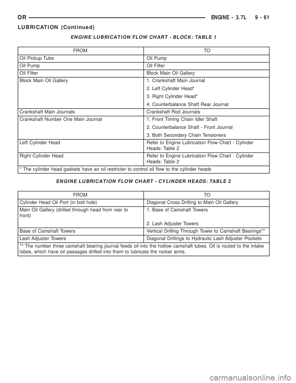
ENGINE LUBRICATION FLOW CHART - BLOCK: TABLE 1
FROM TO
Oil Pickup Tube Oil Pump
Oil Pump Oil Filter
Oil Filter Block Main Oil Gallery
Block Main Oil Gallery 1. Crankshaft Main Journal
2. Left Cylinder Head*
3. Right Cylinder Head*
4. Counterbalance Shaft Rear Journal
Crankshaft Main Journals Crankshaft Rod Journals
Crankshaft Number One Main Journal 1. Front Timing Chain Idler Shaft
2. Counterbalance Shaft - Front Journal
3. Both Secondary Chain Tensioners
Left Cylinder Head Refer to Engine Lubrication Flow Chart - Cylinder
Heads: Table 2
Right Cylinder Head Refer to Engine Lubrication Flow Chart - Cylinder
Heads: Table 2
* The cylinder head gaskets have an oil restricter to control oil flow to the cylinder heads
ENGINE LUBRICATION FLOW CHART - CYLINDER HEADS: TABLE 2
FROM TO
Cylinder Head Oil Port (in bolt hole) Diagonal Cross Drilling to Main Oil Gallery
Main Oil Gallery (drilled through head from rear to
front)1. Base of Camshaft Towers
2. Lash Adjuster Towers
Base of Camshaft Towers Vertical Drilling Through Tower to Camshaft Bearings**
Lash Adjuster Towers Diagonal Drillings to Hydraulic Lash Adjuster Pockets
** The number three camshaft bearing journal feeds oil into the hollow camshaft tubes. Oil is routed to the intake
lobes, which have oil passages drilled into them to lubricate the rocker arms.
DRENGINE - 3.7L 9 - 61
LUBRICATION (Continued)
Page 1311 of 2895
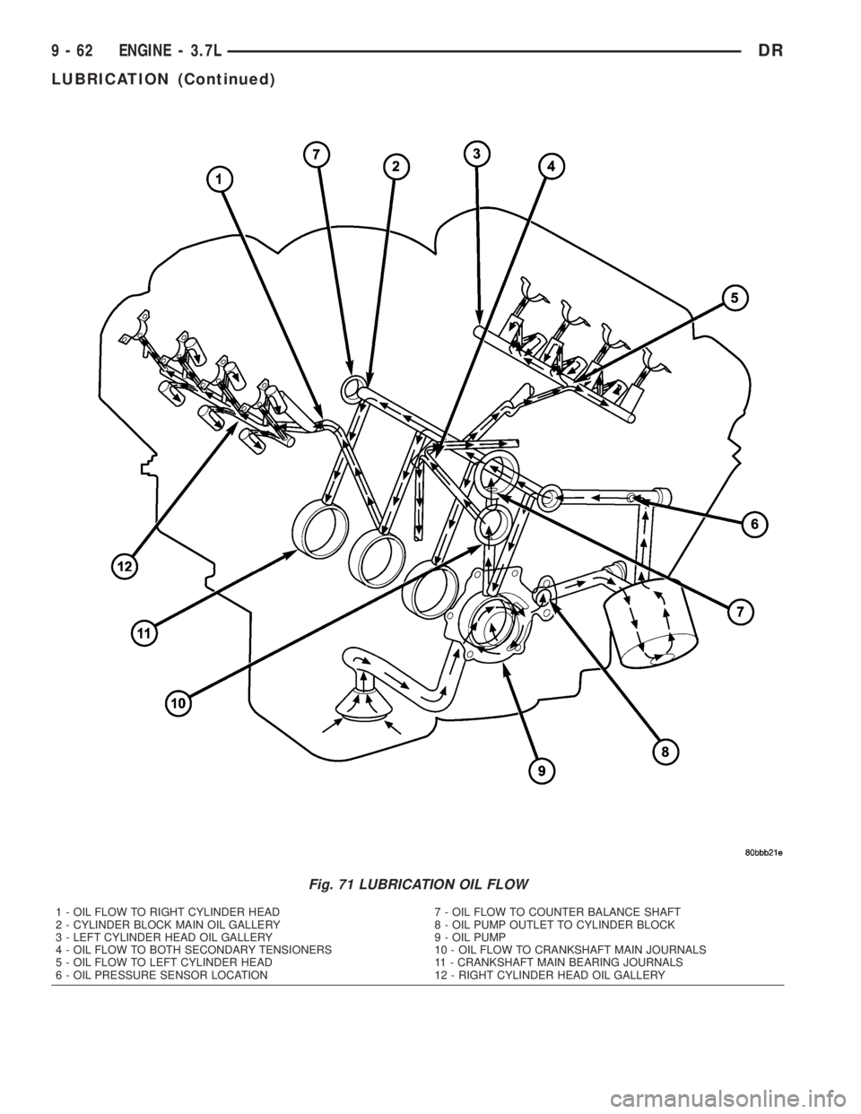
Fig. 71 LUBRICATION OIL FLOW
1 - OIL FLOW TO RIGHT CYLINDER HEAD
2 - CYLINDER BLOCK MAIN OIL GALLERY
3 - LEFT CYLINDER HEAD OIL GALLERY
4 - OIL FLOW TO BOTH SECONDARY TENSIONERS
5 - OIL FLOW TO LEFT CYLINDER HEAD
6 - OIL PRESSURE SENSOR LOCATION7 - OIL FLOW TO COUNTER BALANCE SHAFT
8 - OIL PUMP OUTLET TO CYLINDER BLOCK
9 - OIL PUMP
10 - OIL FLOW TO CRANKSHAFT MAIN JOURNALS
11 - CRANKSHAFT MAIN BEARING JOURNALS
12 - RIGHT CYLINDER HEAD OIL GALLERY
9 - 62 ENGINE - 3.7LDR
LUBRICATION (Continued)