2003 DODGE RAM recommended oil
[x] Cancel search: recommended oilPage 1759 of 2895
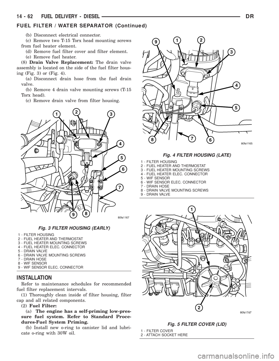
(b) Disconnect electrical connector.
(c) Remove two T-15 Torx head mounting screws
from fuel heater element.
(d) Remove fuel filter cover and filter element.
(e) Remove fuel heater.
(8)Drain Valve Replacement:The drain valve
assembly is located on the side of the fuel filter hous-
ing (Fig. 3) or (Fig. 4).
(a) Disconnect drain hose from the fuel drain
valve.
(b) Remove 4 drain valve mounting screws (T-15
Torx head).
(c) Remove drain valve from filter housing.
INSTALLATION
Refer to maintenance schedules for recommended
fuel filter replacement intervals.
(1) Thoroughly clean inside of filter housing, filter
cap and all related components.
(2)Fuel Filter:
(a)The engine has a self-priming low-pres-
sure fuel system. Refer to Standard Proce-
dures-Fuel System Priming.
(b) Install new o-ring to canister lid and lubri-
cate o-ring with 30W oil.
Fig. 3 FILTER HOUSING (EARLY)
1 - FILTER HOUSING
2 - FUEL HEATER AND THERMOSTAT
3 - FUEL HEATER MOUNTING SCREWS
4 - FUEL HEATER ELEC. CONNECTOR
5 - DRAIN VALVE
6 - DRAIN VALVE MOUNTING SCREWS
7 - DRAIN HOSE
8 - WIF SENSOR
9 - WIF SENSOR ELEC. CONNECTOR
Fig. 4 FILTER HOUSING (LATE)
1 - FILTER HOUSING
2 - FUEL HEATER AND THERMOSTAT
3 - FUEL HEATER MOUNTING SCREWS
4 - FUEL HEATER ELEC. CONNECTOR
5 - WIF SENSOR
6 - WIF SENSOR ELEC. CONNECTOR
7 - DRAIN HOSE
8 - DRAIN VALVE MOUNTING SCREWS
9 - DRAIN VALVE
Fig. 5 FILTER COVER (LID)
1 - FILTER COVER
2 - ATTACH SOCKET HERE
14 - 62 FUEL DELIVERY - DIESELDR
FUEL FILTER / WATER SEPARATOR (Continued)
Page 1766 of 2895
FUEL LINES
DESCRIPTION
Low-Pressure Lines
²the fuel supply line from fuel tank to fuel trans-
fer (lift) pump.
²the fuel return line back to fuel tank.
²the fuel drain manifold line at rear of cylinder
head.
²the fuel supply line from fuel filter to fuel injec-
tion pump.
High-Pressure Lines
²the fuel line from fuel injection pump to overflow
valve.
²the fuel line from fuel injection pump to fuel
rail.
²the 6 fuel lines from fuel rail up to injector con-
nector tubes
WARNING: HIGH-PRESSURE FUEL LINES DELIVER
DIESEL FUEL UNDER EXTREME PRESSURE FROM
THE INJECTION PUMP TO THE FUEL INJECTORS.
THIS MAY BE AS HIGH AS 160,000 KPA (23,206
PSI). USE EXTREME CAUTION WHEN INSPECTING
FOR HIGH-PRESSURE FUEL LEAKS. INSPECT FOR
HIGH-PRESSURE FUEL LEAKS WITH A SHEET OF
CARDBOARD. HIGH FUEL INJECTION PRESSURE
CAN CAUSE PERSONAL INJURY IF CONTACT IS
MADE WITH THE SKIN.
OPERATION
High-Pressure Lines
CAUTION: The high-pressure fuel lines must be
held securely in place in their holders. The lines
cannot contact each other or other components. Do
not attempt to weld high-pressure fuel lines or to
repair lines that are damaged. If lines are ever
kinked or bent, they must be replaced. Use only the
recommended lines when replacement of high-pres-
sure fuel line is necessary.
High-pressure fuel lines deliver fuel (under pres-
sure) of up to approximately 160,000 kPa (23,206
PSI) from the injection pump to the fuel injectors.
The lines expand and contract from the high-pres-
sure fuel pulses generated during the injection pro-
cess. All high-pressure fuel lines are of the same
length and inside diameter. Correct high-pressure
fuel line usage and installation is critical to smooth
engine operation.WARNING: USE EXTREME CAUTION WHEN
INSPECTING FOR HIGH-PRESSURE FUEL LEAKS.
INSPECT FOR HIGH-PRESSURE FUEL LEAKS WITH
A SHEET OF CARDBOARD. HIGH FUEL INJECTION
PRESSURE CAN CAUSE PERSONAL INJURY IF
CONTACT IS MADE WITH THE SKIN.
DIAGNOSIS AND TESTING - HIGH-PRESSURE
FUEL LINE LEAKS
High-pressure fuel line leaks can cause starting
problems and poor engine performance.
WARNING: DUE TO EXTREME FUEL PRESSURES
OF UP TO 160,000 kPa (23,206 PSI), USE EXTREME
CAUTION WHEN INSPECTING FOR HIGH-PRES-
SURE FUEL LEAKS. DO NOT GET YOUR HAND OR
A FINGER NEAR A SUSPECTED LEAK. INSPECT
FOR HIGH-PRESSURE FUEL LEAKS WITH A SHEET
OF CARDBOARD. HIGH FUEL INJECTION PRES-
SURE CAN CAUSE PERSONAL INJURY IF CON-
TACT IS MADE WITH THE SKIN.
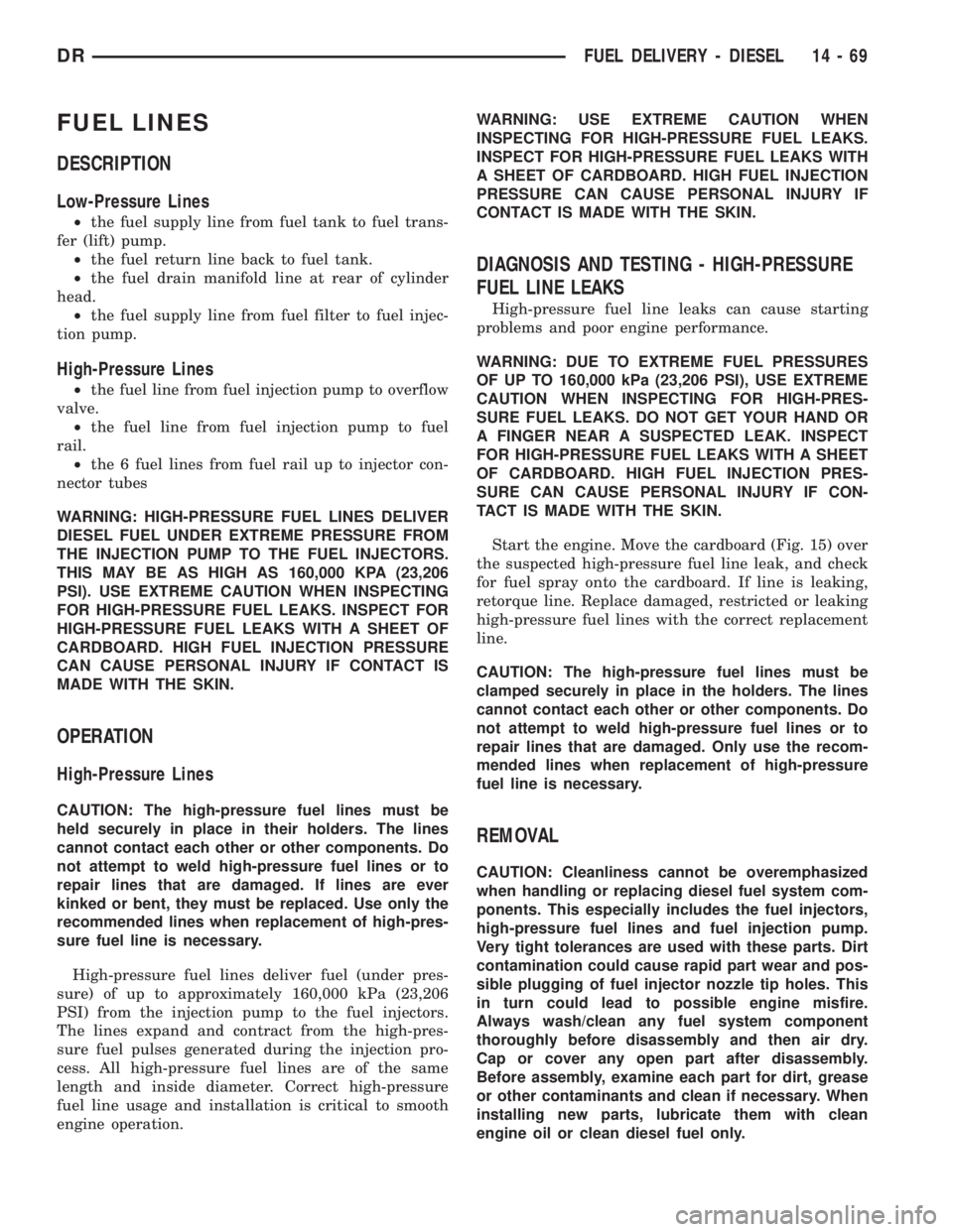
Start the engine. Move the cardboard (Fig. 15) over
the suspected high-pressure fuel line leak, and check
for fuel spray onto the cardboard. If line is leaking,
retorque line. Replace damaged, restricted or leaking
high-pressure fuel lines with the correct replacement
line.
CAUTION: The high-pressure fuel lines must be
clamped securely in place in the holders. The lines
cannot contact each other or other components. Do
not attempt to weld high-pressure fuel lines or to
repair lines that are damaged. Only use the recom-
mended lines when replacement of high-pressure
fuel line is necessary.
REMOVAL
CAUTION: Cleanliness cannot be overemphasized
when handling or replacing diesel fuel system com-
ponents. This especially includes the fuel injectors,
high-pressure fuel lines and fuel injection pump.
Very tight tolerances are used with these parts. Dirt
contamination could cause rapid part wear and pos-
sible plugging of fuel injector nozzle tip holes. This
in turn could lead to possible engine misfire.
Always wash/clean any fuel system component
thoroughly before disassembly and then air dry.
Cap or cover any open part after disassembly.
Before assembly, examine each part for dirt, grease
or other contaminants and clean if necessary. When
installing new parts, lubricate them with clean
engine oil or clean diesel fuel only.
DRFUEL DELIVERY - DIESEL 14 - 69
Page 1813 of 2895
(4) Disconnect and cap the fluid hoses from steer-
ing gear (Refer to 19 - STEERING/PUMP/HOSES -
REMOVAL).
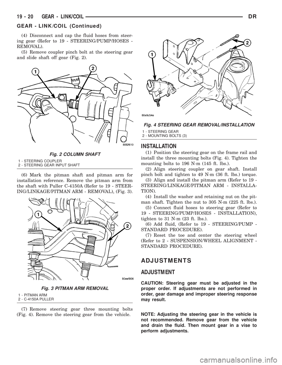
(5) Remove coupler pinch bolt at the steering gear
and slide shaft off gear (Fig. 2).
(6) Mark the pitman shaft and pitman arm for
installation reference. Remove the pitman arm from
the shaft with Puller C-4150A (Refer to 19 - STEER-
ING/LINKAGE/PITMAN ARM - REMOVAL), (Fig. 3).
(7) Remove steering gear three mounting bolts
(Fig. 4). Remove the steering gear from the vehicle.
INSTALLATION
(1) Position the steering gear on the frame rail and
install the three mounting bolts (Fig. 4). Tighten the
mounting bolts to 196 N´m (145 ft. lbs.).
(2) Align steering coupler on gear shaft. Install
pinch bolt and tighten to 49 N´m (36 ft. lbs.) torque.
(3) Align and install the pitman arm (Refer to 19 -
STEERING/LINKAGE/PITMAN ARM - INSTALLA-
TION).
(4) Install the washer and retaining nut on the pit-
man shaft. Tighten the nut to 305 N´m (225 ft. lbs.).
(5) Connect fluid hoses to steering gear (Refer to
19 - STEERING/PUMP/HOSES - INSTALLATION),
tighten to 31 N´m (23 ft. lbs.).
(6) Add fluid, (Refer to 19 - STEERING/PUMP -
STANDARD PROCEDURE).
(7) Reset the toe and center the steering wheel
(Refer to 2 - SUSPENSION/WHEEL ALIGNMENT -
STANDARD PROCEDURE).
ADJUSTMENTS
ADJUSTMENT
CAUTION: Steering gear must be adjusted in the
proper order. If adjustments are not performed in
order, gear damage and improper steering response
may result.
NOTE: Adjusting the steering gear in the vehicle is
not recommended. Remove gear from the vehicle
and drain the fluid. Then mount gear in a vise to
perform adjustments.
Fig. 2 COLUMN SHAFT
1 - STEERING COUPLER
2 - STEERING GEAR INPUT SHAFT
Fig. 3 PITMAN ARM REMOVAL
1 - PITMAN ARM
2 - C-4150A PULLER
Fig. 4 STEERING GEAR REMOVAL/INSTALLATION
1 - STEERING GEAR
2 - MOUNTING BOLTS (3)
19 - 20 GEAR - LINK/COILDR
GEAR - LINK/COIL (Continued)
Page 1827 of 2895
STANDARD PROCEDURE - LUBRICATION
Periodic lubrication of the steering system compo-
nents is required. Refer to Lubrication And Mainte-
nance for the recommended maintenance schedule.
The following components must be lubricated:
²Tie rod
²Tie rod end
²Drag link
SPECIFICATIONS
TORQUE CHART
TORQUE SPECIFICATIONS
DESCRIPTION N´m Ft. Lbs. In. Lbs.
Pitman Arm
Gear Shaft Nut300 225 Ð
Drag Link
Pitman Arm88 65 Ð
Drag Link
Tie Rod108 80 Ð
Drag Link
Adjuster Clamp61 45 Ð
Tie Rod End
Knuckle108 80 Ð
Tie Rod End
Adjuster Clamp61 45 Ð
Stabilizer Bar Link to Axle 68 50 Ð
Steering Damper
Axle95 70 Ð
Steering Damper
Tie Rod81 60 Ð
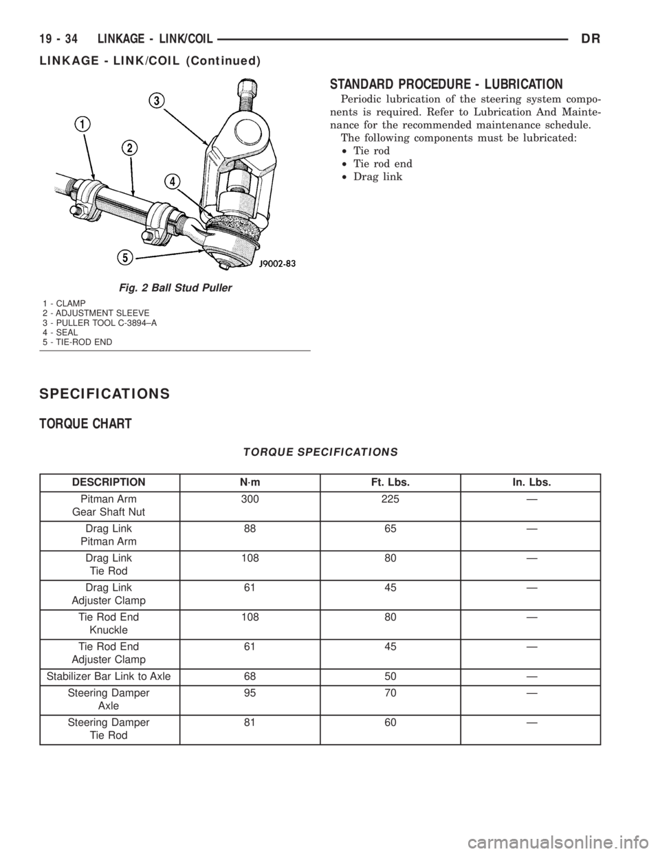
Fig. 2 Ball Stud Puller
1 - CLAMP
2 - ADJUSTMENT SLEEVE
3 - PULLER TOOL C-3894±A
4 - SEAL
5 - TIE-ROD END
19 - 34 LINKAGE - LINK/COILDR
LINKAGE - LINK/COIL (Continued)
Page 1835 of 2895
FLUID
DESCRIPTION
The recommended fluid for the power steering sys-
tem is MopartATF +4.
MopartATF+4, when new is red in color. The
ATF+4 is dyed red so it can be identified from other
fluids used in the vehicle such as engine oil or anti-
freeze. The red color is not permanent and is not an
indicator of fluid condition, As the vehicle is driven,
the ATF+4 will begin to look darker in color and may
eventually become brown.THIS IS NORMAL.
ATF+4 also has a unique odor that may change with
age. Consequently, odor and color cannot be used to
indicate the fluid condition or the need for a fluid
change.
STANDARD PROCEDURE - POWER STEERING
FLUID LEVEL CHECKING
WARNING: FLUID LEVEL SHOULD BE CHECKED
WITH THE ENGINE OFF TO PREVENT PERSONAL
INJURY FROM MOVING PARTS.
CAUTION: MOPARTATF+4 is to be used in the
power steering system. No other power steering or
automatic transmission fluid is to be used in the
system. Damage may result to the power steering
pump and system if any other fluid is used, and do
not overfill.
The power steering fluid level can be viewed on the
dipstick attached to the filler cap. There are two
ranges listed on the dipstick, COLD and HOT. Before
opening power steering system, wipe the reservoir
filler cap free of dirt and debris. Remove the cap and
check the fluid level on its dipstick. When the fluid is
at normal ambient temperature, approximately 21ÉC
to 27ÉC (70ÉF to 80ÉF), the fluid level should read
between the minimum and maximum area of the cold
range. When the fluid is hot, fluid level is allowed to
read up to the highest end of the HOT range. Only
add fluid when the vehicle is cold.
Use only MopartATF+4Do not overfill the
power steering system.
FLUID COOLER
REMOVAL
(1) Drain and siphon the power steering fluid.
(2) Disconnect the return and supply hoses con-
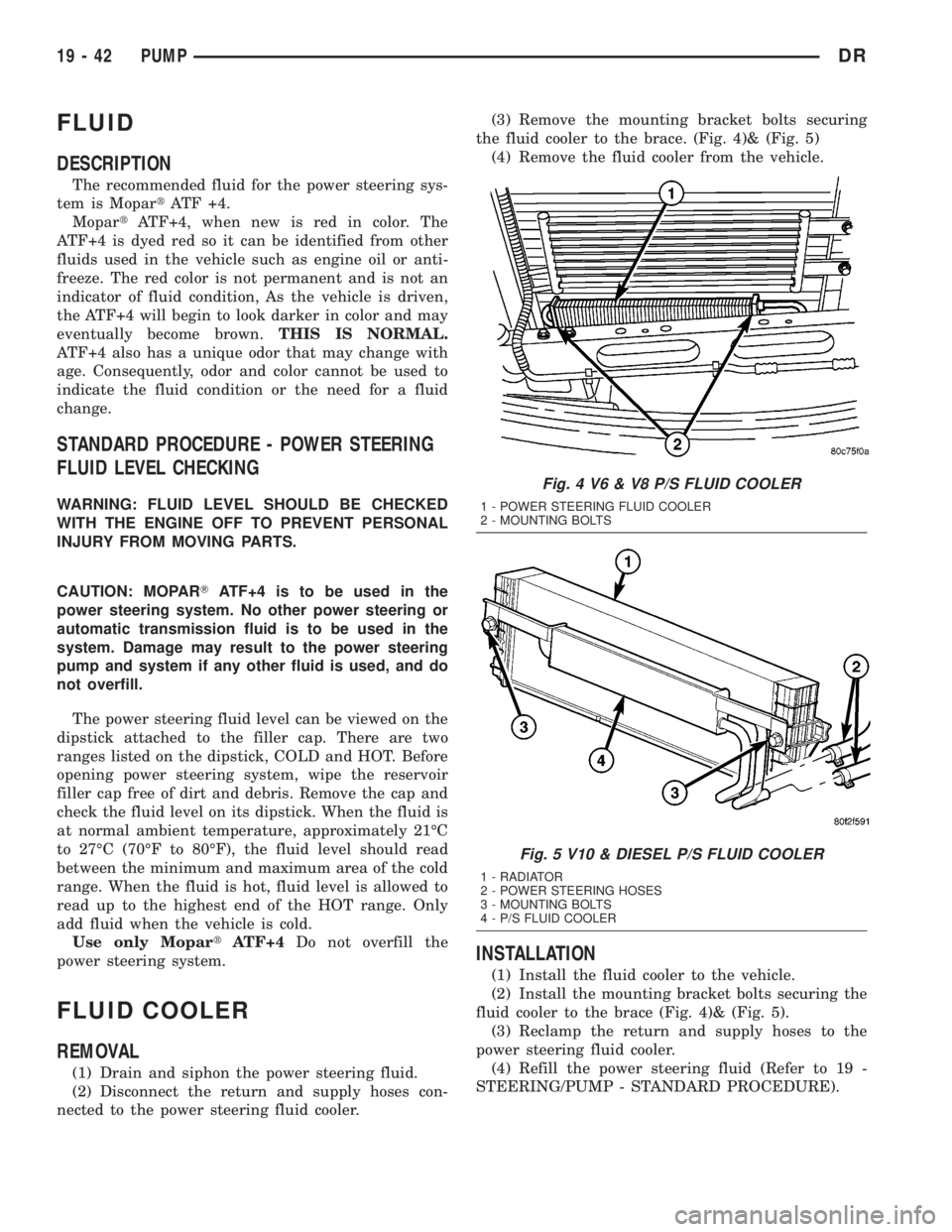
nected to the power steering fluid cooler.(3) Remove the mounting bracket bolts securing
the fluid cooler to the brace. (Fig. 4)& (Fig. 5)
(4) Remove the fluid cooler from the vehicle.
INSTALLATION
(1) Install the fluid cooler to the vehicle.
(2) Install the mounting bracket bolts securing the
fluid cooler to the brace (Fig. 4)& (Fig. 5).
(3) Reclamp the return and supply hoses to the
power steering fluid cooler.
(4) Refill the power steering fluid (Refer to 19 -
STEERING/PUMP - STANDARD PROCEDURE).
Fig. 4 V6 & V8 P/S FLUID COOLER
1 - POWER STEERING FLUID COOLER
2 - MOUNTING BOLTS
Fig. 5 V10 & DIESEL P/S FLUID COOLER
1 - RADIATOR
2 - POWER STEERING HOSES
3 - MOUNTING BOLTS
4 - P/S FLUID COOLER
19 - 42 PUMPDR
Page 1842 of 2895
DIAGNOSIS AND TESTING
LOW LUBRICANT LEVEL
A low transmission lubricant level is generally the
result of a leak, inadequate lubricant fill or an incor-
rect lubricant level check. Leaks can occur at the
mating surfaces of the gear case, adaptor or exten-
sion housing, or from the front/rear seals. A sus-
pected leak could also be the result of an overfill
condition.
Leaks at the rear of the extension or adapter hous-
ing will be from the housing oil seals. Leaks at com-
ponent mating surfaces will probably be the result of
inadequate sealer, gaps in the sealer, incorrect bolt
tightening or use of a non-recommended sealer.
A leak at the front of the transmission will be from
either the front bearing retainer or retainer seal.
Lubricant may be seen dripping from the clutch
housing after extended operation. If the leak is
severe, it may also contaminate the clutch disc caus-
ing the disc to slip, grab and or chatter.
A correct lubricant level check can only be made
when the vehicle is level. Also allow the lubricant to
settle for a minute or so before checking. These rec-
ommendations will ensure an accurate check and
avoid an underfill or overfill condition. Always check
the lubricant level after any addition of fluid to avoid
an incorrect lubricant level condition.
HARD SHIFTING
Hard shifting is usually caused by a low lubricant
level, improper or contaminated lubricants. The con-
sequence of using non-recommended lubricants is
noise, excessive wear, internal bind and hard shift-
ing. Substantial lubricant leaks can result in gear,
shift rail, synchro, and bearing damage. If a leak
goes undetected for an extended period, the first indi-
cations of component damage are usually hard shift-
ing and noise.
Shift component damage or damaged clutch pres-
sure plate or disc are additional probable causes of
increased shift effort. Worn/damaged pressure plate
or disc can cause incorrect release. If clutch problem
is advanced, gear clash during shifts can result.
Worn or damaged synchro rings can cause gear clash
when shifting into any forward gear. In some new or
rebuilt transmissions, new synchro rings may tend to
stick slightly causing hard or noisy shifts. In most
cases this condition will decline as the rings wear-in.
TRANSMISSION NOISE
Most manual transmissions make some noise dur-
ing normal operation. Rotating gears generate a mild
whine that is audible, but generally only at extreme
speeds.Severe highly audible transmission noise is gener-
ally the initial indicator of a lubricant problem.
Insufficient, improper or contaminated lubricant will
promote rapid wear of gears, synchros, shift rails,
forks and bearings. The overheating caused by a
lubricant problem, can also lead to gear and bearing
damage.
REMOVAL
(1) Disconnect battery negative cable.
(2) Shift transmission into Neutral.
(3) Remove shift boot bezel screws and slide boot
upward on shift lever extension.
(4) Remove shift lever extension from the shift
tower and lever assembly.
(5) Raise vehicle on hoist.
(6) Remove skid plate, if equipped.
(7) Drain lubricant if transmission will be disas-
sembled for service.
(8) Mark propeller shaft/shafts and companion
flange yoke/yokes for installation reference and
remove propeller shaft/shafts.
(9) Disconnect harness from clips on transmission
housing.
(10) Remove transfer case linkage if equipped.
(11) Remove transfer case mounting nuts and
remove transfer case if equipped.
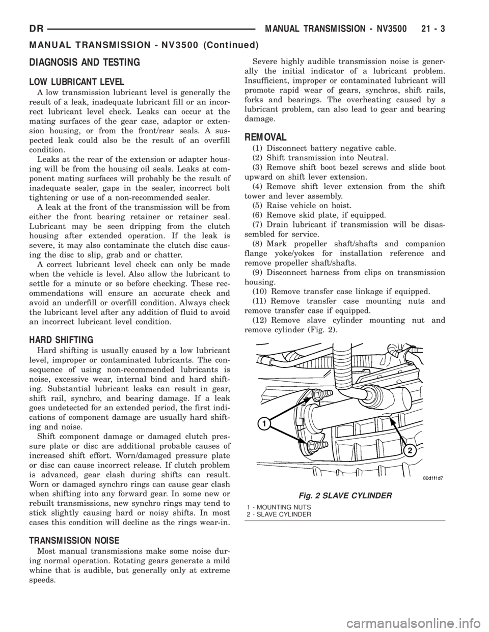
(12) Remove slave cylinder mounting nut and
remove cylinder (Fig. 2).
Fig. 2 SLAVE CYLINDER
1 - MOUNTING NUTS
2 - SLAVE CYLINDER
DRMANUAL TRANSMISSION - NV3500 21 - 3
MANUAL TRANSMISSION - NV3500 (Continued)
Page 1882 of 2895
The driver selects a particular gear by moving the
shift lever to the desired gear position. This move-
ment moves the internal transmission shift compo-
nents to begin the shift sequence. As the shift lever
moves the selected shift rail, the shift fork attached
to that rail begins to move. The fork is positioned in
a groove in the outer circumference of the synchro-
nizer sleeve. As the shift fork moves the synchronizer
sleeve, the synchronizer begins to speed-up or slow
down the selected gear (depending on whether the
driver is up-shifting or down-shifting). The synchro-
nizer does this by having the synchronizer hub
splined to the mainshaft, or the countershaft in some
cases, and moving the blocker ring into contact with
the gear's friction cone. As the blocker ring and fric-
tion cone come together, the gear speed is brought up
or down to the speed of the synchronizer. As the two
speeds match, the splines on the inside of the syn-
chronizer sleeve become aligned with the teeth on
the blocker ring and the friction cone and eventually
will slide over the teeth, locking the gear to the
mainshaft, or countershaft, through the synchronizer.
DIAGNOSIS AND TESTING
LOW LUBRICANT LEVEL
A low transmission lubricant level is generally the
result of a leak, inadequate lubricant fill or an incor-
rect lubricant level check. A correct lubricant level
check can only be made when the vehicle is level.
Also allow the lubricant to settle for a minute or so
before checking. These recommendations will ensure
an accurate check and avoid an underfill or overfill
condition. Always check the lubricant level after any
addition of fluid to avoid an incorrect lubricant level
condition.
Leaks can occur at the mating surfaces of the gear
case, adaptor or extension housing, or from the front/
rear seals. A suspected leak could also be the result
of an overfill condition. Leaks at the rear of the
extension or adapter housing will be from the hous-
ing oil seals. Leaks at component mating surfaces
will probably be the result of inadequate sealer, gaps
in the sealer, incorrect bolt tightening or use of a
non-recommended sealer. A leak at the front of the
transmission will be from either the front bearing
retainer or retainer seal. Lubricant may be seen drip-
ping from the clutch housing after extended opera-
tion. If the leak is severe, it may also contaminate
the clutch disc causing the disc to slip, grab and or
chatter.
HARD SHIFTING
Hard shifting is usually caused by a low lubricant
level, improper or contaminated lubricants. The con-
sequence of using non-recommended lubricants isnoise, excessive wear, internal bind and hard shift-
ing. Substantial lubricant leaks can result in gear,
shift rail, synchro, and bearing damage. If a leak
goes undetected for an extended period, the first indi-
cations of component damage are usually hard shift-
ing and noise.
Component damage, incorrect clutch adjustment or
damaged clutch pressure plate or disc are additional
probable causes of increased shift effort. Incorrect
adjustment or a worn/damaged pressure plate or disc
can cause incorrect release. If clutch problem is
advanced, gear clash during shifts can result. Worn
or damaged synchro rings can cause gear clash when
shifting into any forward gear. In some new or
rebuilt transmissions, new synchro rings may tend to
stick slightly causing hard or noisy shifts. In most
cases this condition will decline as the rings wear-in.
TRANSMISSION NOISE
Most manual transmissions make some noise dur-
ing normal operation. Rotating gears generate a mild
whine that is audible, but generally only at extreme
speeds. Severe highly audible transmission noise is
generally the initial indicator of a lubricant problem.
Insufficient, improper or contaminated lubricant
will promote rapid wear of gears, synchros, shift
rails, forks and bearings. The overheating caused by
a lubricant problem, can also lead to gear breakage.
REMOVAL
(1) Shift transmission into Neutral.
(2) Remove shift boot screws from floorpan and
slide boot upward on the shift lever.
(3) Remove shift lever extension from shift tower
and lever assembly.
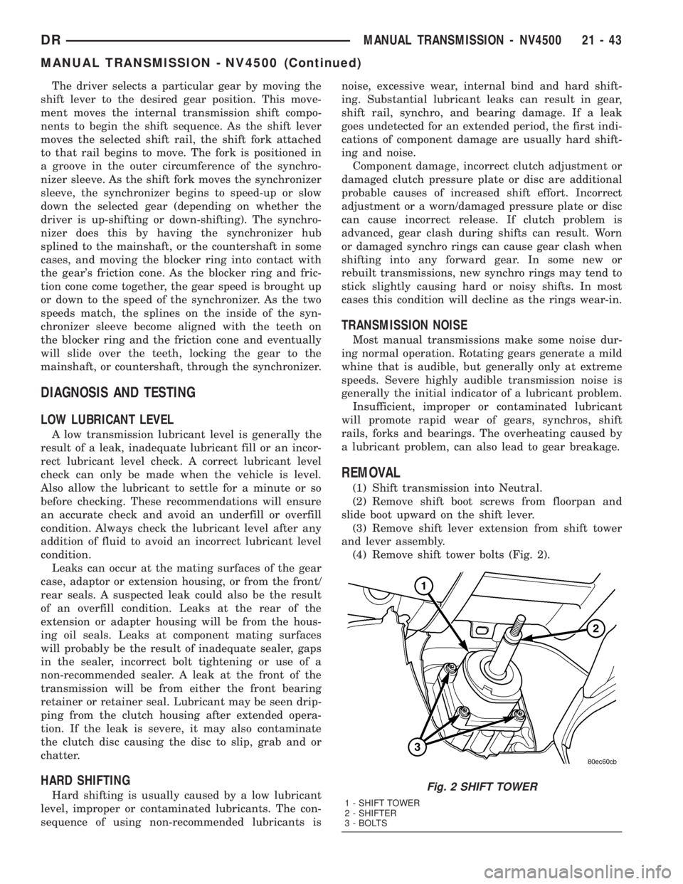
(4) Remove shift tower bolts (Fig. 2).
Fig. 2 SHIFT TOWER
1 - SHIFT TOWER
2 - SHIFTER
3 - BOLTS
DRMANUAL TRANSMISSION - NV4500 21 - 43
MANUAL TRANSMISSION - NV4500 (Continued)
Page 1928 of 2895
IDENTIFICATION
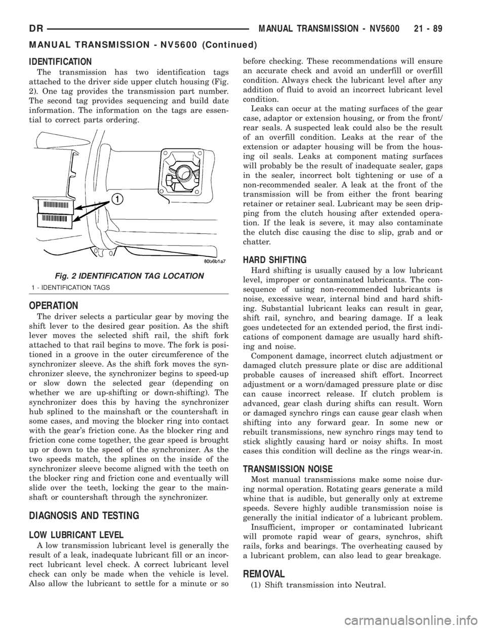
The transmission has two identification tags
attached to the driver side upper clutch housing (Fig.
2). One tag provides the transmission part number.
The second tag provides sequencing and build date
information. The information on the tags are essen-
tial to correct parts ordering.
OPERATION
The driver selects a particular gear by moving the
shift lever to the desired gear position. As the shift
lever moves the selected shift rail, the shift fork
attached to that rail begins to move. The fork is posi-
tioned in a groove in the outer circumference of the
synchronizer sleeve. As the shift fork moves the syn-
chronizer sleeve, the synchronizer begins to speed-up
or slow down the selected gear (depending on
whether we are up-shifting or down-shifting). The
synchronizer does this by having the synchronizer
hub splined to the mainshaft or the countershaft in
some cases, and moving the blocker ring into contact
with the gear's friction cone. As the blocker ring and
friction cone come together, the gear speed is brought
up or down to the speed of the synchronizer. As the
two speeds match, the splines on the inside of the
synchronizer sleeve become aligned with the teeth on
the blocker ring and friction cone and eventually will
slide over the teeth, locking the gear to the main-
shaft or countershaft through the synchronizer.
DIAGNOSIS AND TESTING
LOW LUBRICANT LEVEL
A low transmission lubricant level is generally the
result of a leak, inadequate lubricant fill or an incor-
rect lubricant level check. A correct lubricant level
check can only be made when the vehicle is level.
Also allow the lubricant to settle for a minute or sobefore checking. These recommendations will ensure
an accurate check and avoid an underfill or overfill
condition. Always check the lubricant level after any
addition of fluid to avoid an incorrect lubricant level
condition.
Leaks can occur at the mating surfaces of the gear
case, adaptor or extension housing, or from the front/
rear seals. A suspected leak could also be the result
of an overfill condition. Leaks at the rear of the
extension or adapter housing will be from the hous-
ing oil seals. Leaks at component mating surfaces
will probably be the result of inadequate sealer, gaps
in the sealer, incorrect bolt tightening or use of a
non-recommended sealer. A leak at the front of the
transmission will be from either the front bearing
retainer or retainer seal. Lubricant may be seen drip-
ping from the clutch housing after extended opera-
tion. If the leak is severe, it may also contaminate
the clutch disc causing the disc to slip, grab and or
chatter.
HARD SHIFTING
Hard shifting is usually caused by a low lubricant
level, improper or contaminated lubricants. The con-
sequence of using non-recommended lubricants is
noise, excessive wear, internal bind and hard shift-
ing. Substantial lubricant leaks can result in gear,
shift rail, synchro, and bearing damage. If a leak
goes undetected for an extended period, the first indi-
cations of component damage are usually hard shift-
ing and noise.
Component damage, incorrect clutch adjustment or
damaged clutch pressure plate or disc are additional
probable causes of increased shift effort. Incorrect
adjustment or a worn/damaged pressure plate or disc
can cause incorrect release. If clutch problem is
advanced, gear clash during shifts can result. Worn
or damaged synchro rings can cause gear clash when
shifting into any forward gear. In some new or
rebuilt transmissions, new synchro rings may tend to
stick slightly causing hard or noisy shifts. In most
cases this condition will decline as the rings wear-in.
TRANSMISSION NOISE
Most manual transmissions make some noise dur-
ing normal operation. Rotating gears generate a mild
whine that is audible, but generally only at extreme
speeds. Severe highly audible transmission noise is
generally the initial indicator of a lubricant problem.
Insufficient, improper or contaminated lubricant
will promote rapid wear of gears, synchros, shift
rails, forks and bearings. The overheating caused by
a lubricant problem, can also lead to gear breakage.
REMOVAL
(1) Shift transmission into Neutral.
Fig. 2 IDENTIFICATION TAG LOCATION
1 - IDENTIFICATION TAGS
DRMANUAL TRANSMISSION - NV5600 21 - 89
MANUAL TRANSMISSION - NV5600 (Continued)