2003 DODGE RAM horn
[x] Cancel search: hornPage 1111 of 2895
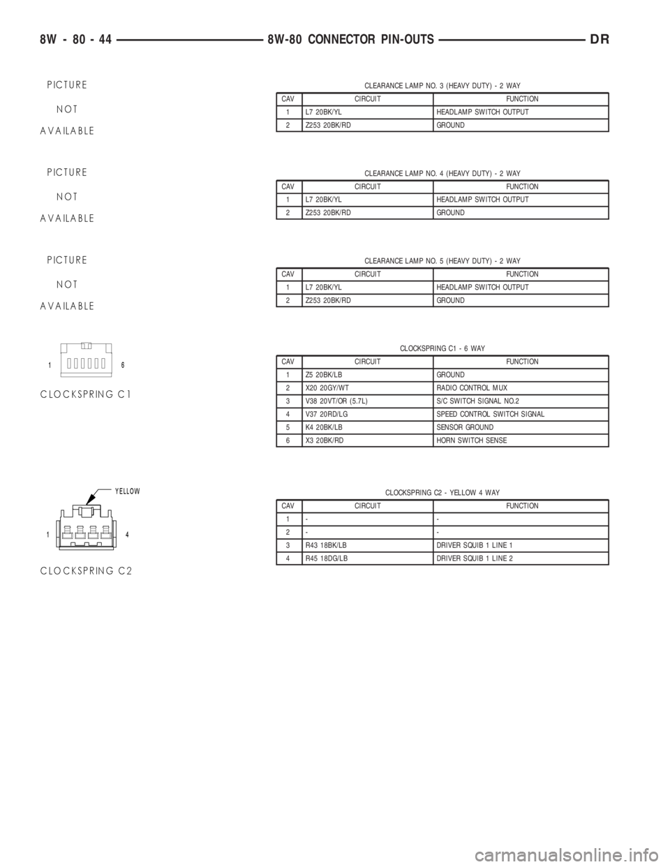
CLEARANCE LAMP NO. 3 (HEAVY DUTY)-2WAY
CAV CIRCUIT FUNCTION
1 L7 20BK/YL HEADLAMP SWITCH OUTPUT
2 Z253 20BK/RD GROUND
CLEARANCE LAMP NO. 4 (HEAVY DUTY)-2WAY
CAV CIRCUIT FUNCTION
1 L7 20BK/YL HEADLAMP SWITCH OUTPUT
2 Z253 20BK/RD GROUND
CLEARANCE LAMP NO. 5 (HEAVY DUTY)-2WAY
CAV CIRCUIT FUNCTION
1 L7 20BK/YL HEADLAMP SWITCH OUTPUT
2 Z253 20BK/RD GROUND
CLOCKSPRING C1-6WAY
CAV CIRCUIT FUNCTION
1 Z5 20BK/LB GROUND
2 X20 20GY/WT RADIO CONTROL MUX
3 V38 20VT/OR (5.7L) S/C SWITCH SIGNAL NO.2
4 V37 20RD/LG SPEED CONTROL SWITCH SIGNAL
5 K4 20BK/LB SENSOR GROUND
6 X3 20BK/RD HORN SWITCH SENSE
CLOCKSPRING C2 - YELLOW 4 WAY
CAV CIRCUIT FUNCTION
1- -
2- -
3 R43 18BK/LB DRIVER SQUIB 1 LINE 1
4 R45 18DG/LB DRIVER SQUIB 1 LINE 2
8W - 80 - 44 8W-80 CONNECTOR PIN-OUTSDR
Page 1112 of 2895
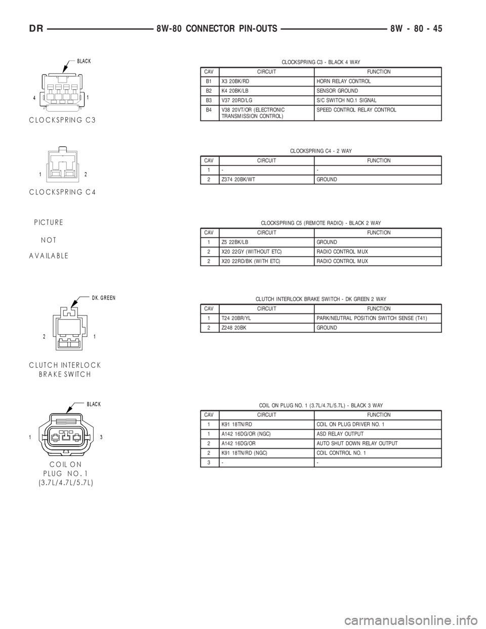
CLOCKSPRING C3 - BLACK 4 WAY
CAV CIRCUIT FUNCTION
B1 X3 20BK/RD HORN RELAY CONTROL
B2 K4 20BK/LB SENSOR GROUND
B3 V37 20RD/LG S/C SWITCH NO.1 SIGNAL
B4 V38 20VT/OR (ELECTRONIC
TRANSMISSION CONTROL)SPEED CONTROL RELAY CONTROL
CLOCKSPRING C4-2WAY
CAV CIRCUIT FUNCTION
1- -
2 Z374 20BK/WT GROUND
CLOCKSPRING C5 (REMOTE RADIO) - BLACK 2 WAY
CAV CIRCUIT FUNCTION
1 Z5 22BK/LB GROUND
2 X20 22GY (WITHOUT ETC) RADIO CONTROL MUX
2 X20 22RD/BK (WITH ETC) RADIO CONTROL MUX
CLUTCH INTERLOCK BRAKE SWITCH - DK GREEN 2 WAY
CAV CIRCUIT FUNCTION
1 T24 20BR/YL PARK/NEUTRAL POSITION SWITCH SENSE (T41)
2 Z248 20BK GROUND
COIL ON PLUG NO. 1 (3.7L/4.7L/5.7L) - BLACK 3 WAY
CAV CIRCUIT FUNCTION
1 K91 18TN/RD COIL ON PLUG DRIVER NO. 1
1 A142 16DG/OR (NGC) ASD RELAY OUTPUT
2 A142 16DG/OR AUTO SHUT DOWN RELAY OUTPUT
2 K91 18TN/RD (NGC) COIL CONTROL NO. 1
3- -
DR8W-80 CONNECTOR PIN-OUTS 8W - 80 - 45
Page 1132 of 2895
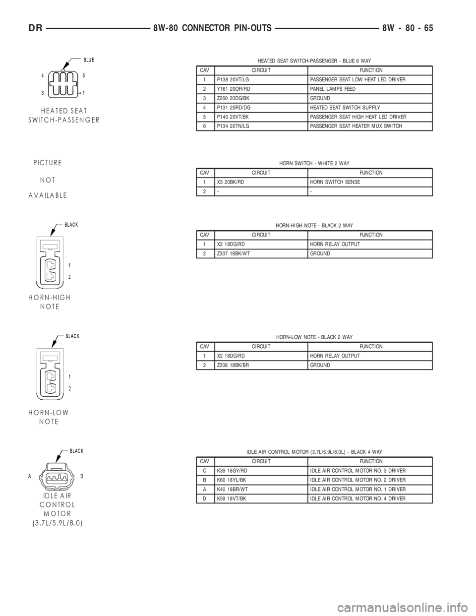
HEATED SEAT SWITCH-PASSENGER - BLUE 6 WAY
CAV CIRCUIT FUNCTION
1 P138 20VT/LG PASSENGER SEAT LOW HEAT LED DRIVER
2 Y161 20OR/RD PANEL LAMPS FEED
3 Z260 20DG/BK GROUND
4 P131 20RD/DG HEATED SEAT SWITCH SUPPLY
5 P140 20VT/BK PASSENGER SEAT HIGH HEAT LED DRIVER
6 P134 20TN/LG PASSENGER SEAT HEATER MUX SWITCH
HORN SWITCH - WHITE 2 WAY
CAV CIRCUIT FUNCTION
1 X3 20BK/RD HORN SWITCH SENSE
2- -
HORN-HIGH NOTE - BLACK 2 WAY
CAV CIRCUIT FUNCTION
1 X2 18DG/RD HORN RELAY OUTPUT
2 Z307 18BK/WT GROUND
HORN-LOW NOTE - BLACK 2 WAY
CAV CIRCUIT FUNCTION
1 X2 18DG/RD HORN RELAY OUTPUT
2 Z308 18BK/BR GROUND
IDLE AIR CONTROL MOTOR (3.7L/5.9L/8.0L) - BLACK 4 WAY
CAV CIRCUIT FUNCTION
C K39 18GY/RD IDLE AIR CONTROL MOTOR NO. 3 DRIVER
B K60 18YL/BK IDLE AIR CONTROL MOTOR NO. 2 DRIVER
A K40 18BR/WT IDLE AIR CONTROL MOTOR NO. 1 DRIVER
D K59 18VT/BK IDLE AIR CONTROL MOTOR NO. 4 DRIVER
DR8W-80 CONNECTOR PIN-OUTS 8W - 80 - 65
Page 1135 of 2895
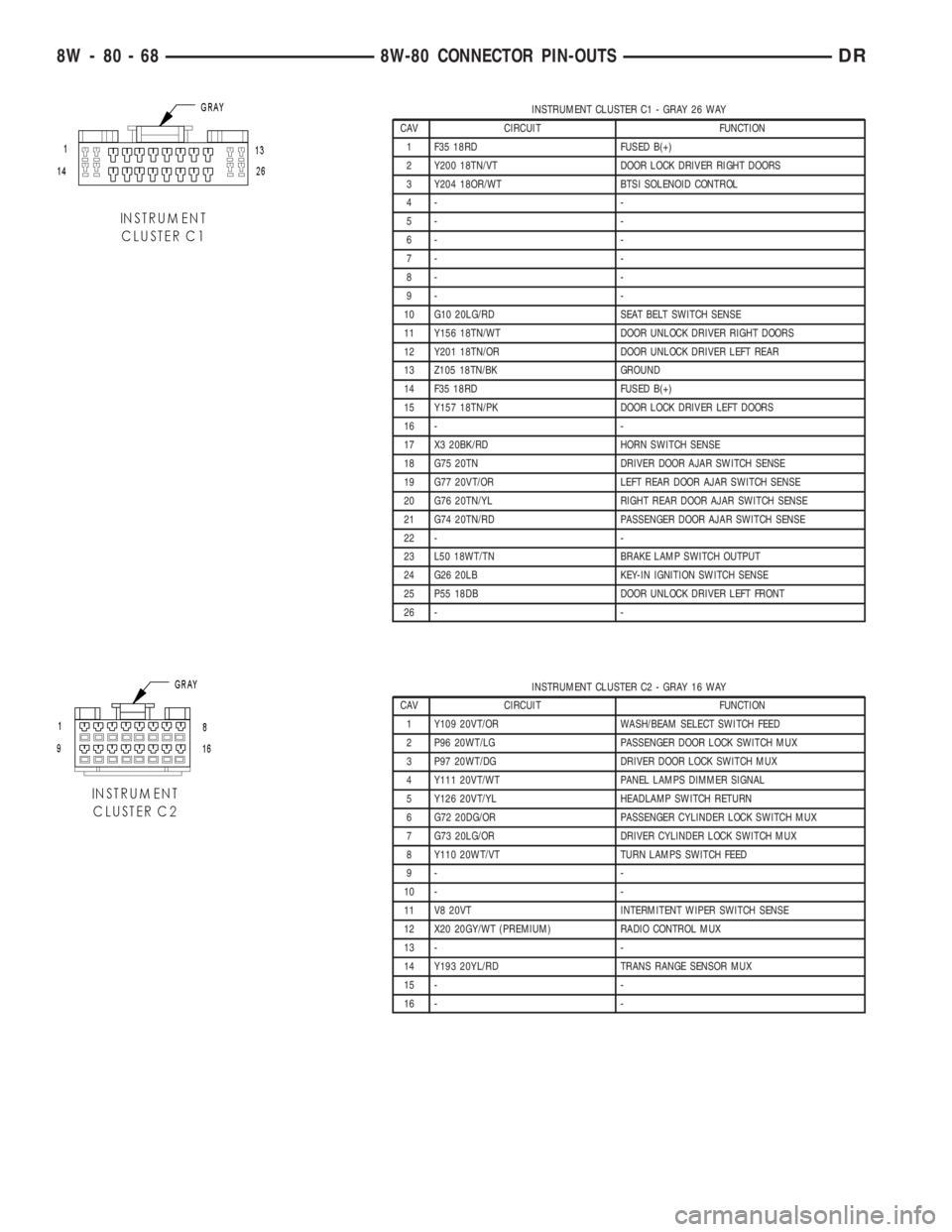
INSTRUMENT CLUSTER C1 - GRAY 26 WAY
CAV CIRCUIT FUNCTION
1 F35 18RD FUSED B(+)
2 Y200 18TN/VT DOOR LOCK DRIVER RIGHT DOORS
3 Y204 18OR/WT BTSI SOLENOID CONTROL
4- -
5- -
6- -
7- -
8- -
9- -
10 G10 20LG/RD SEAT BELT SWITCH SENSE
11 Y156 18TN/WT DOOR UNLOCK DRIVER RIGHT DOORS
12 Y201 18TN/OR DOOR UNLOCK DRIVER LEFT REAR
13 Z105 18TN/BK GROUND
14 F35 18RD FUSED B(+)
15 Y157 18TN/PK DOOR LOCK DRIVER LEFT DOORS
16 - -
17 X3 20BK/RD HORN SWITCH SENSE
18 G75 20TN DRIVER DOOR AJAR SWITCH SENSE
19 G77 20VT/OR LEFT REAR DOOR AJAR SWITCH SENSE
20 G76 20TN/YL RIGHT REAR DOOR AJAR SWITCH SENSE
21 G74 20TN/RD PASSENGER DOOR AJAR SWITCH SENSE
22 - -
23 L50 18WT/TN BRAKE LAMP SWITCH OUTPUT
24 G26 20LB KEY-IN IGNITION SWITCH SENSE
25 P55 18DB DOOR UNLOCK DRIVER LEFT FRONT
26 - -
INSTRUMENT CLUSTER C2 - GRAY 16 WAY
CAV CIRCUIT FUNCTION
1 Y109 20VT/OR WASH/BEAM SELECT SWITCH FEED
2 P96 20WT/LG PASSENGER DOOR LOCK SWITCH MUX
3 P97 20WT/DG DRIVER DOOR LOCK SWITCH MUX
4 Y111 20VT/WT PANEL LAMPS DIMMER SIGNAL
5 Y126 20VT/YL HEADLAMP SWITCH RETURN
6 G72 20DG/OR PASSENGER CYLINDER LOCK SWITCH MUX
7 G73 20LG/OR DRIVER CYLINDER LOCK SWITCH MUX
8 Y110 20WT/VT TURN LAMPS SWITCH FEED
9- -
10 - -
11 V8 20VT INTERMITENT WIPER SWITCH SENSE
12 X20 20GY/WT (PREMIUM) RADIO CONTROL MUX
13 - -
14 Y193 20YL/RD TRANS RANGE SENSOR MUX
15 - -
16 - -
8W - 80 - 68 8W-80 CONNECTOR PIN-OUTSDR
Page 1137 of 2895
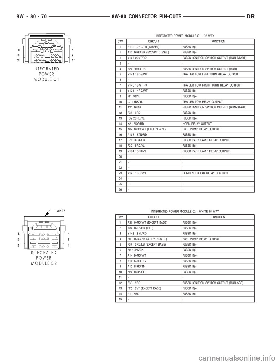
INTEGRATED POWER MODULE C1 - 26 WAY
CAV CIRCUIT FUNCTION
1 A112 12RD/TN (DIESEL) FUSED B(+)
1 A17 16RD/BK (EXCEPT DIESEL) FUSED B(+)
2 Y107 20VT/RD FUSED IGNITION SWITCH OUTPUT (RUN-START)
3- -
4 A20 20RD/DB FUSED IGNITION SWITCH OUTPUT (RUN)
5 Y141 18DG/WT TRAILER TOW LEFT TURN RELAY OUTPUT
6- -
7 Y140 18WT/PK TRAILER TOW RIGHT TURN RELAY OUTPUT
8 Y131 14RD/WT FUSED B(+)
9 M1 18PK FUSED B(+)
10 L7 18BK/YL TRAILER TOW RELAY OUTPUT
11 A21 16DB FUSED IGNITION SWITCH OUTPUT (RUN-START)
12 F35 18RD FUSED B(+)
13 F32 20RD/YL FUSED B(+)
14 X2 18DG/RD HORN RELAY OUTPUT
15 A64 16DG/WT (EXCEPT 4.7L) FUEL PUMP RELAY OUTPUT
16 A108 18TN/RD FUSED B(+)
17 L76 18BK/OR FUSED PARK LAMP RELAY OUTPUT
18 F32 18RD/YL FUSED B(+)
19 Y174 18PK/VT FUSED PARK LAMP RELAY OUTPUT
20 - -
21 - -
22 - -
23 Y145 18DB/YL CONDENSER FAN RELAY CONTROL
24 - -
25 - - -
26 - -
INTEGRATED POWER MODULE C2 - WHITE 15 WAY
CAV CIRCUIT FUNCTION
1 A30 10RD/WT (EXCEPT BASE) FUSED B(+)
2 A34 16LB/RD (ETC) FUSED B(+)
3 Y148 18YL/RD FUSED B(+)
4 A61 16DG/BK (3.9L/5.7L/5.9L) FUEL PUMP RELAY OUTPUT
5 F37 12RD/LB (EXCEPT BASE) FUSED B(+)
6 A2 10PK/BK FUSED B(+)
7 A14 20RD/WT FUSED B(+)
8 A10 14RD/DG FUSED B(+)
9 A12 18RD/TN FUSED B(+)
10 A22 16BK/OR FUSED B(+)
11 - -
12 F30 18RD FUSED IGNITION SWITCH OUTPUT (RUN-ACC)
13 F75 18VT (EXCEPT BASE) FUSED B(+)
14 A1 16RD FUSED B(+)
15 - -
8W - 80 - 70 8W-80 CONNECTOR PIN-OUTSDR
Page 1182 of 2895
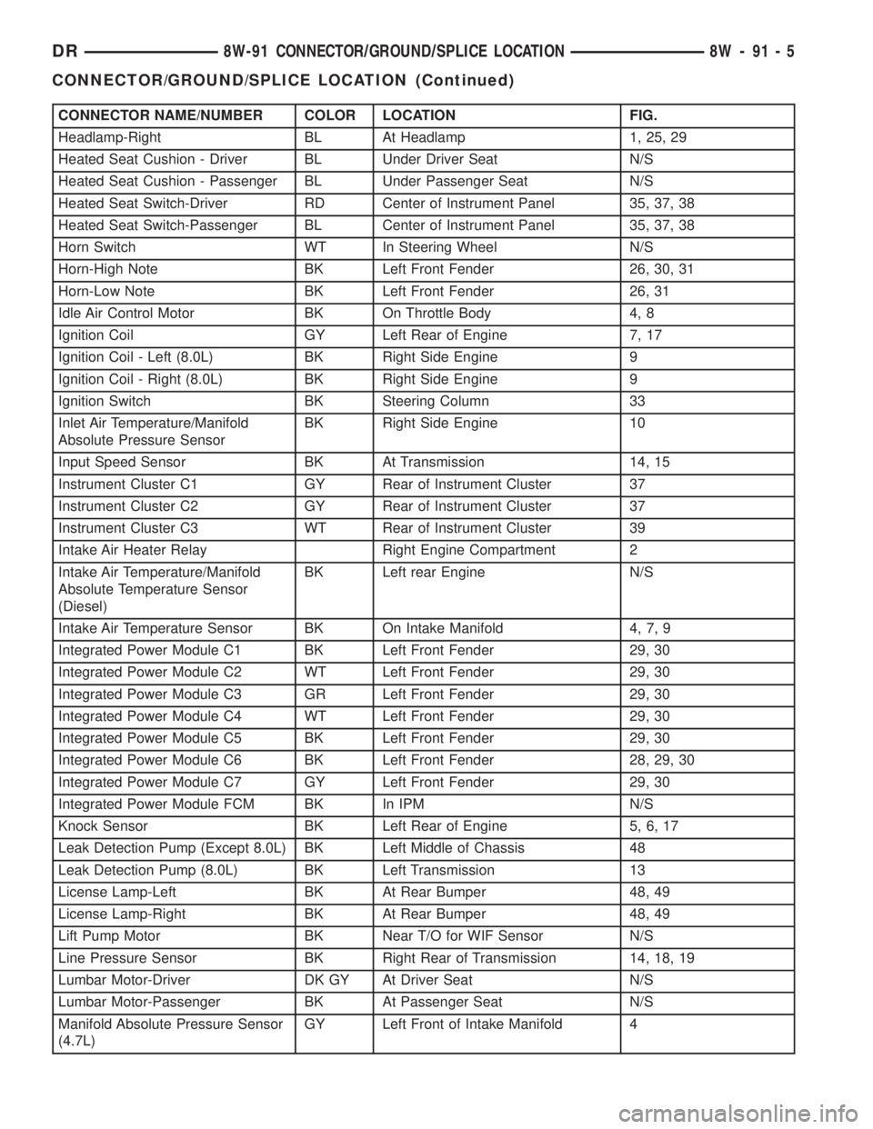
CONNECTOR NAME/NUMBER COLOR LOCATION FIG.
Headlamp-Right BL At Headlamp 1, 25, 29
Heated Seat Cushion - Driver BL Under Driver Seat N/S
Heated Seat Cushion - Passenger BL Under Passenger Seat N/S
Heated Seat Switch-Driver RD Center of Instrument Panel 35, 37, 38
Heated Seat Switch-Passenger BL Center of Instrument Panel 35, 37, 38
Horn Switch WT In Steering Wheel N/S
Horn-High Note BK Left Front Fender 26, 30, 31
Horn-Low Note BK Left Front Fender 26, 31
Idle Air Control Motor BK On Throttle Body 4, 8
Ignition Coil GY Left Rear of Engine 7, 17
Ignition Coil - Left (8.0L) BK Right Side Engine 9
Ignition Coil - Right (8.0L) BK Right Side Engine 9
Ignition Switch BK Steering Column 33
Inlet Air Temperature/Manifold
Absolute Pressure SensorBK Right Side Engine 10
Input Speed Sensor BK At Transmission 14, 15
Instrument Cluster C1 GY Rear of Instrument Cluster 37
Instrument Cluster C2 GY Rear of Instrument Cluster 37
Instrument Cluster C3 WT Rear of Instrument Cluster 39
Intake Air Heater Relay Right Engine Compartment 2
Intake Air Temperature/Manifold
Absolute Temperature Sensor
(Diesel)BK Left rear Engine N/S
Intake Air Temperature Sensor BK On Intake Manifold 4, 7, 9
Integrated Power Module C1 BK Left Front Fender 29, 30
Integrated Power Module C2 WT Left Front Fender 29, 30
Integrated Power Module C3 GR Left Front Fender 29, 30
Integrated Power Module C4 WT Left Front Fender 29, 30
Integrated Power Module C5 BK Left Front Fender 29, 30
Integrated Power Module C6 BK Left Front Fender 28, 29, 30
Integrated Power Module C7 GY Left Front Fender 29, 30
Integrated Power Module FCM BK In IPM N/S
Knock Sensor BK Left Rear of Engine 5, 6, 17
Leak Detection Pump (Except 8.0L) BK Left Middle of Chassis 48
Leak Detection Pump (8.0L) BK Left Transmission 13
License Lamp-Left BK At Rear Bumper 48, 49
License Lamp-Right BK At Rear Bumper 48, 49
Lift Pump Motor BK Near T/O for WIF Sensor N/S
Line Pressure Sensor BK Right Rear of Transmission 14, 18, 19
Lumbar Motor-Driver DK GY At Driver Seat N/S
Lumbar Motor-Passenger BK At Passenger Seat N/S
Manifold Absolute Pressure Sensor
(4.7L)GY Left Front of Intake Manifold 4
DR8W-91 CONNECTOR/GROUND/SPLICE LOCATION 8W - 91 - 5
CONNECTOR/GROUND/SPLICE LOCATION (Continued)
Page 1244 of 2895
tery and provides the primary means of circuit pro-
tection and power distribution for all vehicle
electrical systems. The front control module controls
power to some of these vehicle systems electrical and
electromechanical loads based on inputs received
from hard wired switch inputs and data received on
the PCI bus circuit (J1850).
For information on theIntegrated Power Mod-
ule Refer to the Power Distribution Sectionof
the service manual.
OPERATION
As messages are sent over the PCI bus circuit, the
front control module reads these messages and con-
trols power to some of the vehicles electrical systems
by completing the circuit to ground (low side driver)
or completing the circuit to 12 volt power (high side
driver). The following functions areControlledby
the Front Control Module:
²Headlamp Power with Voltage Regulation
²Windshield Wiper ªON/OFFº Relay Actuation
²Windshield Wiper ªHI/LOº Relay Actuation
²Windshield Washer Pump Motor
²Fog Lamp Relay Actuation
²Park Lamp Relay Actuation
²Horn Relay Actuation
The following inputs areReceived/Monitoredby
the Front Control Module:
²B+ Connection Detection²Power Ground
²Ambient Temperature Sensing
²Ignition Switch Run
²Washer Fluid Level Switch
²Windshield Wiper Park Switch
²PCI Bus Circuit
DIAGNOSIS AND TESTING - FRONT CONTROL
MODULE
The front control module is a printed circuit board
based module with a on-board micro-processor. The
front control module interfaces with other electronic
modules in the vehicle via the Programmable Com-
munications Interface (PCI) data bus (J1850). In
order to obtain conclusive testing the Programmable
Communications Interface (PCI) data bus network
and all of the electronic modules that provide inputs
to, or receive outputs from the front control module
must be checked. All PCI (J1850) communication
faults must be resolved prior to further diagnosing
any front control module related issues.
The front control module was designed to be diag-
nosed with an appropriate diagnostic scan tool, such
as the DRB IIIt. The most reliable, efficient, and
accurate means to diagnose the front control module
requires the use of a DRB IIItscan tool and the
proper Body Diagnostic Procedures manual.
Before any testing of the front control module is
attempted, the battery should be fully charged and
all wire harness and ground connections inspected
around the affected areas on the vehicle.
REMOVAL
(1) Disconnect the positive and negative battery
cables from the battery.
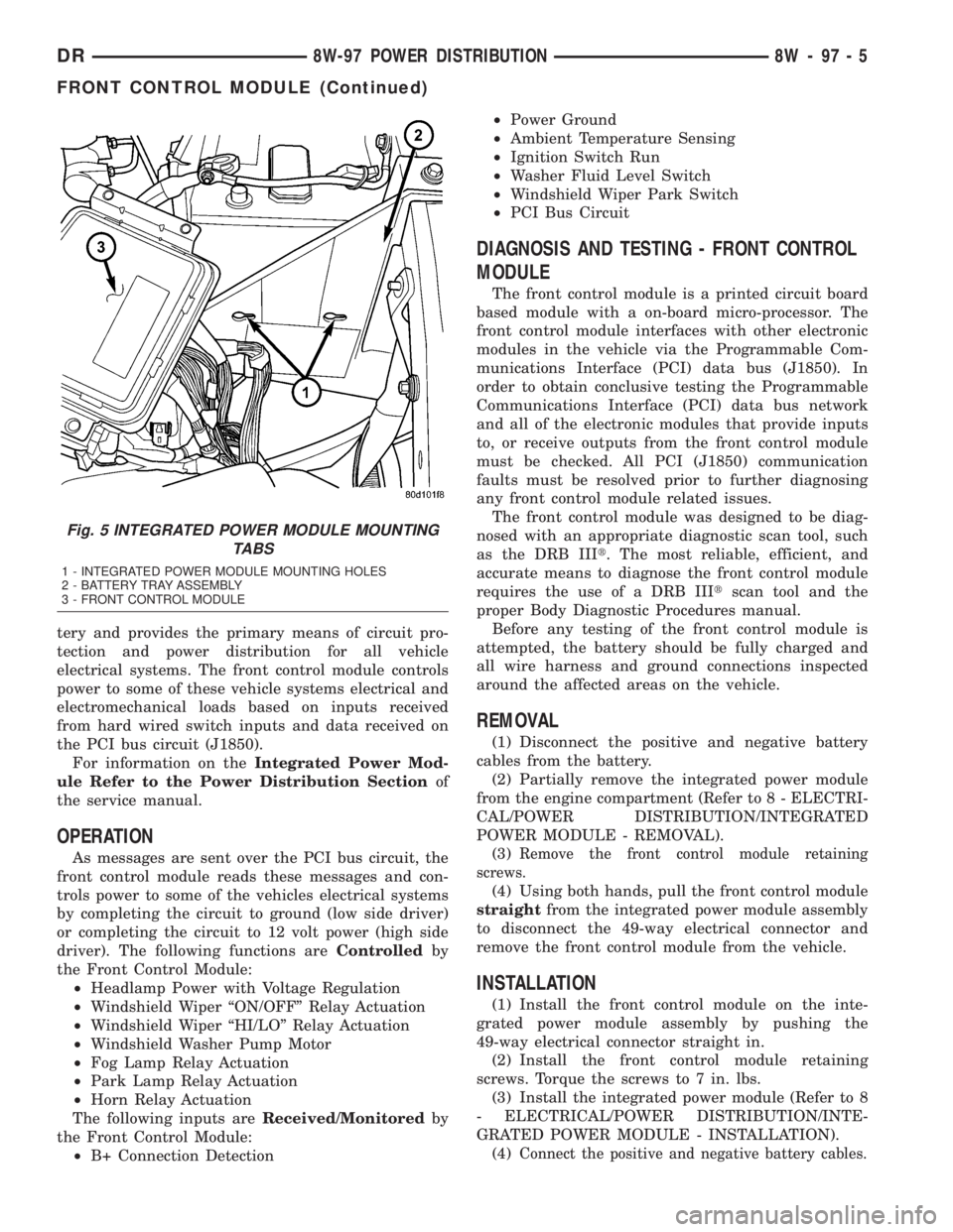
(2) Partially remove the integrated power module
from the engine compartment (Refer to 8 - ELECTRI-
CAL/POWER DISTRIBUTION/INTEGRATED
POWER MODULE - REMOVAL).
(3)
Remove the front control module retaining
screws.
(4) Using both hands, pull the front control module
straightfrom the integrated power module assembly
to disconnect the 49-way electrical connector and
remove the front control module from the vehicle.
INSTALLATION
(1) Install the front control module on the inte-
grated power module assembly by pushing the
49-way electrical connector straight in.
(2) Install the front control module retaining
screws. Torque the screws to 7 in. lbs.
(3) Install the integrated power module (Refer to 8
- ELECTRICAL/POWER DISTRIBUTION/INTE-
GRATED POWER MODULE - INSTALLATION).
(4)
Connect the positive and negative battery cables.
Fig. 5 INTEGRATED POWER MODULE MOUNTING
TABS
1 - INTEGRATED POWER MODULE MOUNTING HOLES
2 - BATTERY TRAY ASSEMBLY
3 - FRONT CONTROL MODULE
DR8W-97 POWER DISTRIBUTION 8W - 97 - 5
FRONT CONTROL MODULE (Continued)
Page 1802 of 2895
INSTALLATION
WARNING: BEFORE SERVICING THE STEERING
COLUMN THE AIRBAG SYSTEM MUST BE DIS-
ARMED. REFER TO ELECTRICAL RESTRAINT SYS-
TEM FOR SERVICE PROCEDURES. FAILURE TO DO
SO MAY RESULT IN ACCIDENTAL DEPLOYMENT OF
THE AIRBAG AND POSSIBLE PERSONAL INJURY.
CAUTION: All fasteners must be torqued to specifi-
cation to ensure proper operation of the steering
column.
(1) Position the steering column on the dash panel
support and loosely install the mounting nuts.
(2) Firmly slide the steering column upward
against the studs in dash panel and hand tighten the
nuts.
(3) Install the steering shaft coupler on the steer-
ing shaft and loosely install anewbolt.
(4) Center steering column in dash opening and
tighten mounting nuts to 28 N´m (250 in. lbs.).
NOTE: Torque the upper left nut first then the lower
right nut. Then torque the lower left nut then the
upper right nut.
NOTE: A new bolt must be used for reinstallation.
(5) Tighten the coupler bolt to 57 N´m (42 ft. lbs.).
(6) Install a new brake light switch (Refer to 8 -
ELECTRICAL/LAMPS/LIGHTING - EXTERIOR/
BRAKE LAMP SWITCH - REMOVAL).(7) Install the shifter cable. (Refer to 21 - TRANS-
MISSION/TRANSAXLE/AUTOMATIC - 32RH/GEAR
SHIFT CABLE - INSTALLATION)
(8) Connect the wiring harness to the column.
(9) Install the SKIM module.
(10) Install the clockspring(Refer to 8 - ELECTRI-
CAL/RESTRAINTS/CLOCKSPRING - REMOVAL).
(11) Install the shrouds.
(12) Install the steering column opening cover
(Refer to 23 - BODY/INSTRUMENT PANEL/STEER-
ING COLUMN OPENING COVER - INSTALLA-
TION).
(13) Align the spline on the wheel hub to shaft.
(14) Then install the steering wheel and install a
newbolt. Tighten the bolt to 61 N´m (45 ft. lbs.).
(15) Install the airbag (Refer to 8 - ELECTRICAL/
RESTRAINTS/DRIVER AIRBAG - INSTALLATION).
(16) Install the two steering wheel switches.
(17) Install the tilt lever handle.
(18) Install the negative battery terminal.
(19) Test the operation of the horn, Electronic
PRNDL Indicator, lights and any other functions that
are steering column operated.IGNITION SWITCH
DESCRIPTION
The ignition switch is located on the steering col-
umn. It is used as the main on/off switching device
for most electrical components. The mechanical key
cylinder is used to engage/disengage the electrical
ignition switch.
OPERATION
Vehicles equipped with an automatic trans-
mission and a steering column mounted shifter:
an interlock device is located within the shift cable.
This interlock device is used to lock the transmission
shifter in the PARK position when the key cylinder is
in any position and the brake pedal is not depressed.
DIAGNOSIS AND TESTING - IGNITION SWITCH
TEST AND REPAIR
If the key removal effort is excessive on a vehicle
with a automatic transmission first adjust the shift
linkage, (Refer to 21 - TRANSMISSION/TRANS-
AXLE/AUTOMATIC - 46RE/GEAR SHIFT CABLE -
ADJUSTMENTS).
If the ignition switch effort is excessive remove the
ignition key cylinder from the steering column. (Refer
to 19 - STEERING/COLUMN/LOCK CYLINDER
HOUSING - REMOVAL). Check the turning effort of
the key cylinder. If the ignition key cylinder effort is
excessive replace the key cylinder.
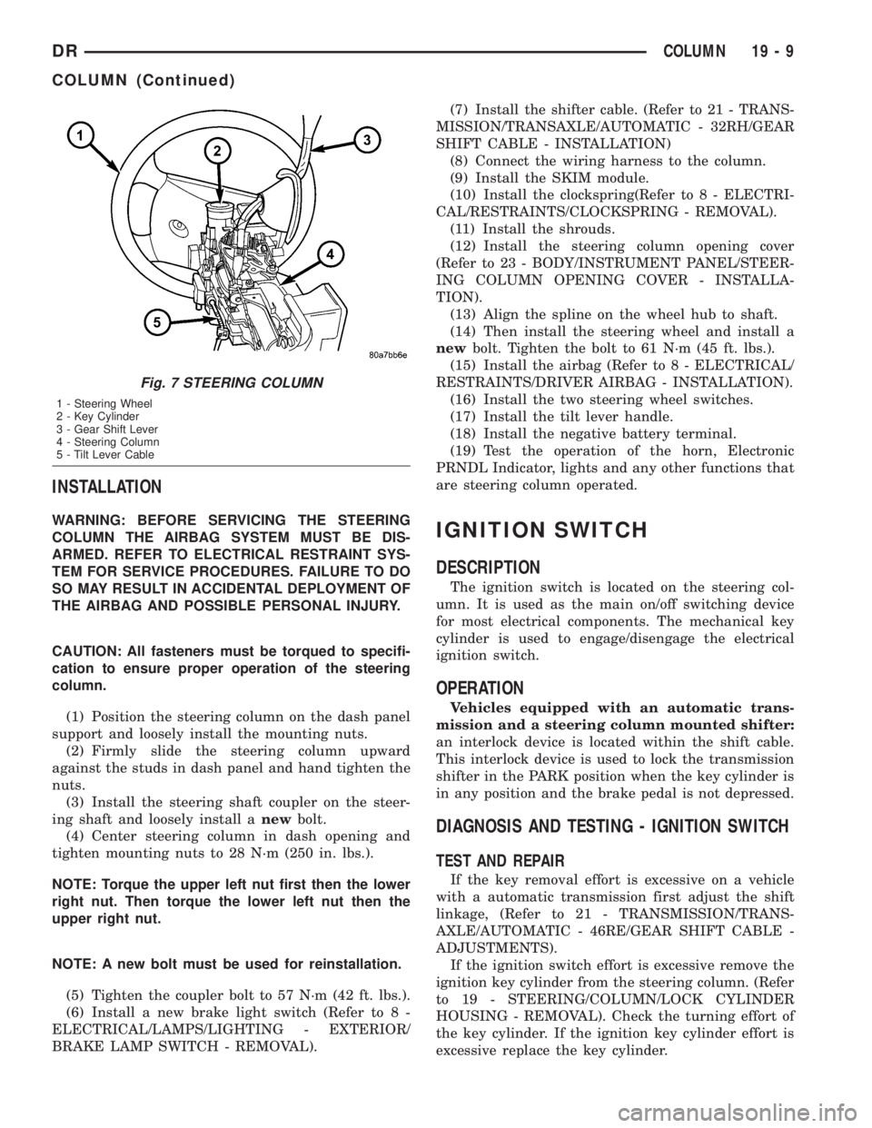
Fig. 7 STEERING COLUMN
1 - Steering Wheel
2 - Key Cylinder
3 - Gear Shift Lever
4 - Steering Column
5 - Tilt Lever Cable
DRCOLUMN 19 - 9
COLUMN (Continued)