2003 DODGE RAM transmission fluid
[x] Cancel search: transmission fluidPage 401 of 2895

NOTE: If the TCM has been replaced, the ªQuick Learn
Procedureº must be performed. (Refer to 8 - ELECTRI-
CAL/ELECTRONIC CONTROL MODULES/TRANSMIS-
SION CONTROL MODULE - STANDARD PROCEDURE)
BATTERY FEED
A fused, direct battery feed to the TCM is used for
continuous power. This battery voltage is necessary
to retain memory in the TCM. When the battery (B+)
is disconnected, this memory is lost. When the bat-
tery (B+) is restored, this memory loss is detected by
the TCM and a Diagnostic Trouble Code (DTC) is set.
CLUTCH VOLUME INDEXES (CVI)
An important function of the TCM is to monitor
Clutch Volume Indexes (CVI). CVIs represent the vol-
ume of fluid needed to compress a clutch pack.
The TCM monitors gear ratio changes by monitor-
ing the Input and Output Speed Sensors. The Input,
or Turbine Speed Sensor sends an electrical signal to
the TCM that represents input shaft rpm. The Out-
put Speed Sensor provides the TCM with output
shaft speed information.
By comparing the two inputs, the TCM can deter-
mine transmission gear position. This is important to
the CVI calculation because the TCM determines
CVIs by monitoring how long it takes for a gear
change to occur (Fig. 11).
Gear ratios can be determined by using the
DRBIIItScan Tool and reading the Input/Output
Speed Sensor values in the ªMonitorsº display. Gear
ratio can be obtained by dividing the Input Speed
Sensor value by the Output Speed Sensor value.
For example, if the input shaft is rotating at 1000
rpm and the output shaft is rotating at 500 rpm,
then the TCM can determine that the gear ratio is
2:1. In direct drive (3rd gear), the gear ratio changes
to 1:1. The gear ratio changes as clutches are applied
and released. By monitoring the length of time it
takes for the gear ratio to change following a shift
request, the TCM can determine the volume of fluid
used to apply or release a friction element.
The volume of transmission fluid needed to apply
the friction elements are continuously updated for
adaptive controls. As friction material wears, the vol-
ume of fluid need to apply the element increases.
Certain mechanical problems within the input
clutch assembly can cause inadequate or out-of-range
element volumes. Also, defective Input/Output Speed
Sensors and wiring can cause these conditions. The
following chart identifies the appropriate clutch vol-
umes and when they are monitored/updated:
CLUTCH VOLUMES
Clutch When UpdatedProper Clutch
Volume
L/R2-1 or 3-1
downshift45 to 134
2C3-2 kickdown
shift25 to 85
OD 2-3 upshift 30 to 100
4C 3-4 upshift 30 to 85
UD4-3 kickdown
shift30 to 100
SHIFT SCHEDULES
As mentioned earlier, the TCM has programming that
allows it to select a variety of shift schedules. Shift
schedule selection is dependent on the following:
²Shift lever position
²Throttle position
²Engine load
²Fluid temperature
²Software level
As driving conditions change, the TCM appropri-
ately adjusts the shift schedule. Refer to the follow-
ing chart to determine the appropriate operation
expected, depending on driving conditions.
Fig. 11 Example of CVI Calculation
1 - OUTPUT SPEED SENSOR
2 - OUTPUT SHAFT
3 - CLUTCH PACK
4 - SEPARATOR PLATE
5 - FRICTION DISCS
6 - INPUT SHAFT
7 - INPUT SPEED SENSOR
8 - PISTON AND SEAL
8E - 20 ELECTRONIC CONTROL MODULESDR
TRANSMISSION CONTROL MODULE (Continued)
Page 495 of 2895

WASHER FLUID INDICATOR
DESCRIPTION.........................42
OPERATION...........................42WATER-IN-FUEL INDICATOR
DESCRIPTION.........................43
OPERATION...........................43
INSTRUMENT CLUSTER
DESCRIPTION
The instrument cluster for this model is an Elec-
troMechanical Instrument Cluster (EMIC) that is
located in the instrument panel above the steering
column opening, directly in front of the driver (Fig.
1). The remainder of the EMIC, including the mounts
and the electrical connections, are concealed within
the instrument panel behind the cluster bezel.
Besides analog gauges and indicators, the EMIC
module incorporates two blue-green digital Vacuum
Fluorescent Display (VFD) units for displaying odom-
eter/trip odometer information, engine hours, auto-
matic transmission gear selector position (PRNDL),
several warning or reminder indications and certain
diagnostic information. The instrument cluster for
this model also includes the hardware and software
necessary to serve as the electronic body control mod-
ule and is sometimes referred to as the Cab Com-
partment Node or CCN.
The EMIC gauges and indicators are visible
through a dedicated opening in the cluster bezel on
the instrument panel and are protected by a clear
plastic cluster lens (Fig. 2) that is integral to a clus-
ter lens, hood and mask unit. Just behind the cluster
lens is the cluster hood and an integral cluster mask,
which are constructed of molded black plastic. The
cluster hood serves as a visor and shields the face of
the cluster from ambient light and reflections to
reduce glare, while the cluster mask serves to sepa-
rate and define the individual gauges and indicators
of the EMIC. A black plastic odometer/trip odometerswitch button protrudes through dedicated holes in
the cluster mask and the cluster lens, located near
the lower edge of the cluster just to the left of the
tachometer. The molded plastic EMIC lens, hood and
mask unit has four integral mounting tabs, one each
on the upper and lower outboard corners of the unit.
These mounting tabs are used to secure the EMIC to
the molded plastic instrument panel cluster carrier
with four screws.
The rear of the cluster housing and the EMIC elec-
tronic circuitry are protected by a molded plastic rear
cover, which is secured to the cluster housing with a
single screw, while eight screws installed around the
outside perimeter of the rear cover secure it to the
cluster lens, hood and mask unit. The rear cover
includes clearance holes for service access to each of
the eleven incandescent bulb and bulb holder units
installed on the cluster circuit board for general illu-
mination lighting and for the cluster connector recep-
tacles. The connector receptacles on the back of the
cluster electronic circuit board connect the EMIC to
the vehicle electrical system through three take outs
with connectors from the instrument panel wire har-
ness. The EMIC also has an integral interface con-
nector on the back of the cluster circuit board that
joins it to the optional external RKE receiver through
a connector receptacle that is integral to that unit.
The rear cover includes a molded receptacle and two
latch features to secure the RKE receiver on vehicles
that are so equipped.
Sandwiched between the rear cover and the lens,
hood and mask unit is the cluster housing. The
Fig. 1 Instrument Cluster
1 - INSTRUMENT PANEL
2 - INSTRUMENT CLUSTER
Fig. 2 Instrument Cluster Components
1 - SCREW (9)
2 - REAR COVER
3 - CLUSTER HOUSING
4 - LENS, HOOD & MASK
8J - 2 INSTRUMENT CLUSTERDR
Page 498 of 2895

the vehicle speed remains greater than about twenty-
four kilometers-per-hour (fifteen miles-per-hour).
²Vacuum Fluorescent Display Synchroniza-
tion- The EMIC transmits electronic panel lamp
dimming level messages which allows all other elec-
tronic modules on the PCI data bus with Vacuum
Fluorescent Display (VFD) units to coordinate their
illumination intensity with that of the EMIC VFD
units.
²Vehicle Theft Security System- The EMIC
monitors inputs from the door cylinder lock switch-
(es), the door ajar switches, the ignition switch, and
the Remote Keyless Entry (RKE) receiver module,
then provides electronic horn and lighting request
messages to the Front Control Module (FCM) located
on the Integrated Power Module (IPM) for the appro-
priate VTSS alarm output features.
²Wiper/Washer System Control- The EMIC
provides electronic wiper and/or washer request mes-
sages to the Front Control Module (FCM) located on
the Integrated Power Module (IPM) for the appropri-
ate wiper and washer system features. (Refer to 8 -
ELECTRICAL/WIPERS/WASHERS - DESCRIP-
TION).
The EMIC houses six analog gauges and has pro-
visions for up to twenty-three indicators (Fig. 3) or
(Fig. 4). The EMIC includes the following analog
gauges:
²Coolant Temperature Gauge
²Fuel Gauge
²Oil Pressure Gauge
²Speedometer
²Tachometer
²Voltage Gauge
Some of the EMIC indicators are automatically
configured when the EMIC is connected to the vehi-
cle electrical system for compatibility with certain
optional equipment or equipment required for regula-
tory purposes in certain markets. While each EMIC
may have provisions for indicators to support every
available option, the configurable indicators will not
be functional in a vehicle that does not have the
equipment that an indicator supports. The EMIC
includes provisions for the following indicators (Fig.
3) or (Fig. 4):
²Airbag Indicator (with Airbag System only)
²Antilock Brake System (ABS) Indicator
(with ABS or Rear Wheel Anti-Lock [RWAL]
brakes only)
²Brake Indicator
²Cargo Lamp Indicator
²Check Gauges Indicator
²Cruise Indicator (with Speed Control only)
²Door Ajar Indicator
²Electronic Throttle Control (ETC) Indicator
(with 5.7L Gasoline Engine only)²Gear Selector Indicator (with Automatic
Transmission only)
²High Beam Indicator
²Lamp Out Indicator
²Low Fuel Indicator
²Malfunction Indicator Lamp (MIL)
²Overdrive-Off Indicator (with Automatic
Transmission only)
²Seatbelt Indicator
²Security Indicator (with Sentry Key Immo-
bilizer & Vehicle Theft Security Systems only)
²Service Four-Wheel Drive Indicator (with
Four-Wheel Drive only)
²Transmission Overtemp Indicator (with
Automatic Transmission only)
²Turn Signal (Right and Left) Indicators
²Upshift Indicator (with Manual Transmis-
sion only)
²Washer Fluid Indicator
²Wait-To-Start Indicator (with Diesel Engine
only)
²Water-In-Fuel Indicator (with Diesel Engine
only)
Each indicator in the EMIC, except those located
within one of the VFD units, is illuminated by a ded-
icated LED that is soldered onto the EMIC electronic
circuit board. The LED units are not available for
service replacement and, if damaged or faulty, the
entire EMIC must be replaced. Cluster illumination
is accomplished by dimmable incandescent back
lighting, which illuminates the gauges for visibility
when the exterior lighting is turned on. Each of the
incandescent bulbs is secured by an integral bulb
holder to the electronic circuit board from the back of
the cluster housing.
Hard wired circuitry connects the EMIC to the
electrical system of the vehicle. These hard wired cir-
cuits are integral to several wire harnesses, which
are routed throughout the vehicle and retained by
many different methods. These circuits may be con-
nected to each other, to the vehicle electrical system
and to the EMIC through the use of a combination of
soldered splices, splice block connectors, and many
different types of wire harness terminal connectors
and insulators. Refer to the appropriate wiring infor-
mation. The wiring information includes wiring dia-
grams, proper wire and connector repair procedures,
further details on wire harness routing and reten-
tion, as well as pin-out and location views for the
various wire harness connectors, splices and grounds.
The EMIC modules for this model are serviced only
as complete units. The EMIC module cannot be
adjusted or repaired. If a gauge, an LED indicator, a
VFD unit, the electronic circuit board, the circuit
board hardware, the cluster overlay, or the EMIC
housing are damaged or faulty, the entire EMIC mod-
DRINSTRUMENT CLUSTER 8J - 5
INSTRUMENT CLUSTER (Continued)
Page 499 of 2895

ule must be replaced. The cluster lens, hood and
mask unit and the individual incandescent lamp
bulbs with holders are available for individual ser-
vice replacement.
OPERATION
The ElectroMechanical Instrument Cluster (EMIC)
in this model also includes the hardware and soft-
ware necessary to serve as the electronic body control
module and is sometimes referred to as the Cab
Compartment Node or CCN. The following informa-
tion deals primarily with the instrument cluster
functions of this unit. Additional details of the elec-
tronic body control functions of this unit may be
found within the service information for the system
or component that the EMIC controls. For example:
Additional details of the audible warning functions of
the EMIC are found within the Chime/Buzzer service
information.The EMIC is designed to allow the vehicle operator
to monitor the conditions of many of the vehicle com-
ponents and operating systems. The gauges and indi-
cators in the EMIC provide valuable information
about the various standard and optional powertrains,
fuel and emissions systems, cooling systems, lighting
systems, safety systems and many other convenience
items. The EMIC is installed in the instrument panel
so that all of these monitors can be easily viewed by
the vehicle operator when driving, while still allow-
ing relative ease of access for service. The micropro-
cessor-based EMIC hardware and software uses
various inputs to control the gauges and indicators
visible on the face of the cluster. Some of these
inputs are hard wired, but most are in the form of
electronic messages that are transmitted by other
electronic modules over the Programmable Communi-
cations Interface (PCI) data bus network. (Refer to 8
- ELECTRICAL/ELECTRONIC CONTROL MOD-
ULES/COMMUNICATION - OPERATION).
Fig. 3 Gauges & Indicators - Gasoline Engine
1 - MALFUNCTION INDICATOR LAMP 13 - ELECTRONIC THROTTLE CONTROL (ETC) INDICATOR
2 - VOLTAGE GAUGE 14 - ENGINE TEMPERATURE GAUGE
3 - LEFT TURN INDICATOR 15 - SECURITY INDICATOR
4 - TACHOMETER 16 - GEAR SELECTOR INDICATOR DISPLAY (INCLUDES
CRUISE & UPSHIFT INDICATORS)
5 - AIRBAG INDICATOR 17 - CHECK GAUGES INDICATOR
6 - HIGH BEAM INDICATOR 18 - BRAKE INDICATOR
7 - SEATBELT INDICATOR 19 - ABS INDICATOR
8 - SPEEDOMETER 20 - ODOMETER/TRIP ODOMETER DISPLAY (INCLUDES
ENGINE HOURS, WASHER FLUID, LAMP OUTAGE,
OVERDRIVE-OFF & SERVICE 4x4 INDICATORS)
9 - RIGHT TURN INDICATOR 21 - ODOMETER/TRIP ODOMETER SWITCH BUTTON
10 - OIL PRESSURE GAUGE 22 - FUEL GAUGE
11 - CARGO LAMP INDICATOR 23 - LOW FUEL INDICATOR
12 - DOOR AJAR INDICATOR 24 - TRANSMISSION OVERTEMP INDICATOR
8J - 6 INSTRUMENT CLUSTERDR
INSTRUMENT CLUSTER (Continued)
Page 500 of 2895
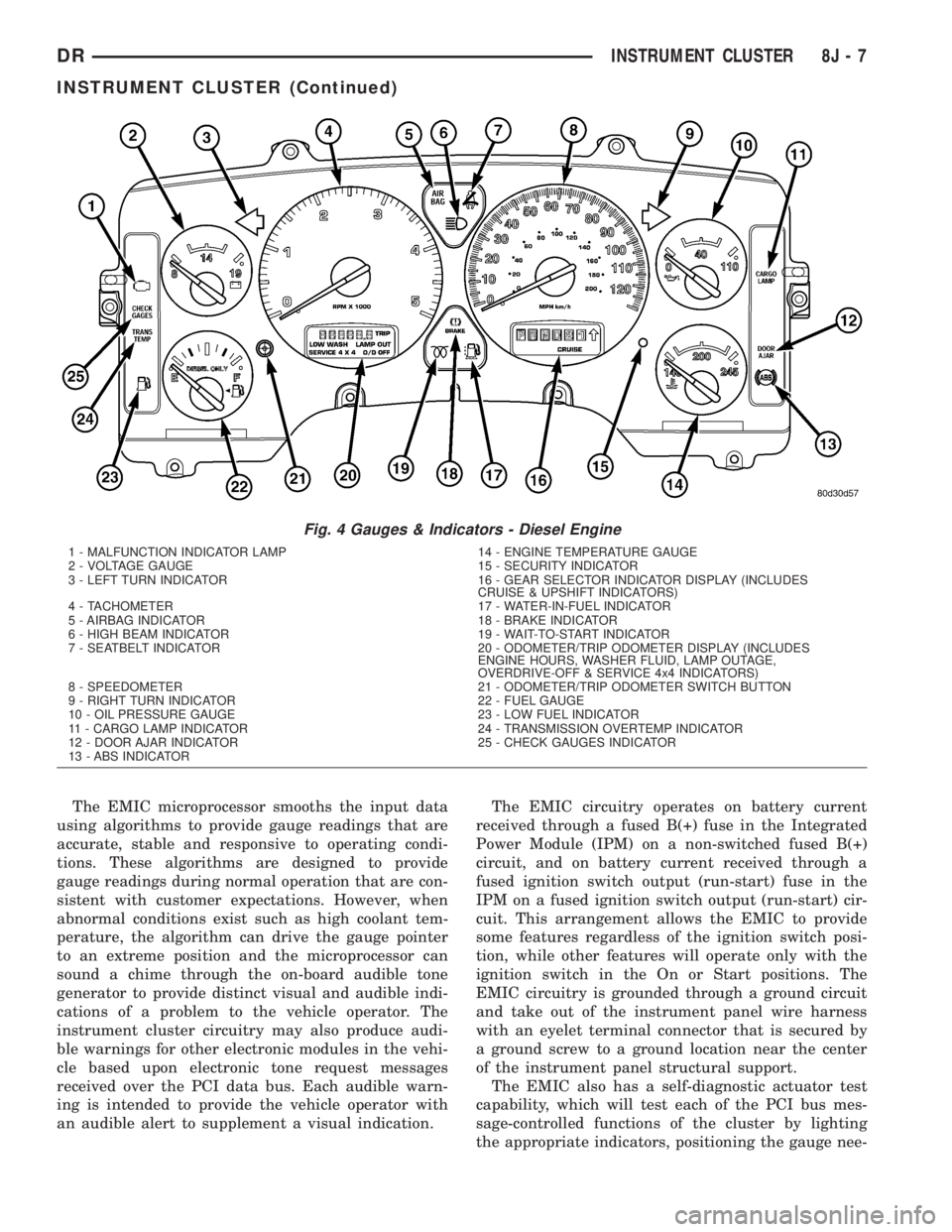
The EMIC microprocessor smooths the input data
using algorithms to provide gauge readings that are
accurate, stable and responsive to operating condi-
tions. These algorithms are designed to provide
gauge readings during normal operation that are con-
sistent with customer expectations. However, when
abnormal conditions exist such as high coolant tem-
perature, the algorithm can drive the gauge pointer
to an extreme position and the microprocessor can
sound a chime through the on-board audible tone
generator to provide distinct visual and audible indi-
cations of a problem to the vehicle operator. The
instrument cluster circuitry may also produce audi-
ble warnings for other electronic modules in the vehi-
cle based upon electronic tone request messages
received over the PCI data bus. Each audible warn-
ing is intended to provide the vehicle operator with
an audible alert to supplement a visual indication.The EMIC circuitry operates on battery current
received through a fused B(+) fuse in the Integrated
Power Module (IPM) on a non-switched fused B(+)
circuit, and on battery current received through a
fused ignition switch output (run-start) fuse in the
IPM on a fused ignition switch output (run-start) cir-
cuit. This arrangement allows the EMIC to provide
some features regardless of the ignition switch posi-
tion, while other features will operate only with the
ignition switch in the On or Start positions. The
EMIC circuitry is grounded through a ground circuit
and take out of the instrument panel wire harness
with an eyelet terminal connector that is secured by
a ground screw to a ground location near the center
of the instrument panel structural support.
The EMIC also has a self-diagnostic actuator test
capability, which will test each of the PCI bus mes-
sage-controlled functions of the cluster by lighting
the appropriate indicators, positioning the gauge nee-
Fig. 4 Gauges & Indicators - Diesel Engine
1 - MALFUNCTION INDICATOR LAMP 14 - ENGINE TEMPERATURE GAUGE
2 - VOLTAGE GAUGE 15 - SECURITY INDICATOR
3 - LEFT TURN INDICATOR 16 - GEAR SELECTOR INDICATOR DISPLAY (INCLUDES
CRUISE & UPSHIFT INDICATORS)
4 - TACHOMETER 17 - WATER-IN-FUEL INDICATOR
5 - AIRBAG INDICATOR 18 - BRAKE INDICATOR
6 - HIGH BEAM INDICATOR 19 - WAIT-TO-START INDICATOR
7 - SEATBELT INDICATOR 20 - ODOMETER/TRIP ODOMETER DISPLAY (INCLUDES
ENGINE HOURS, WASHER FLUID, LAMP OUTAGE,
OVERDRIVE-OFF & SERVICE 4x4 INDICATORS)
8 - SPEEDOMETER 21 - ODOMETER/TRIP ODOMETER SWITCH BUTTON
9 - RIGHT TURN INDICATOR 22 - FUEL GAUGE
10 - OIL PRESSURE GAUGE 23 - LOW FUEL INDICATOR
11 - CARGO LAMP INDICATOR 24 - TRANSMISSION OVERTEMP INDICATOR
12 - DOOR AJAR INDICATOR 25 - CHECK GAUGES INDICATOR
13 - ABS INDICATOR
DRINSTRUMENT CLUSTER 8J - 7
INSTRUMENT CLUSTER (Continued)
Page 531 of 2895

onds, the gauge needle will return to the left end of
the gauge scale.
²Actuator Test- Each time the cluster is put
through the actuator test, the tachometer needle will
be swept to several calibration points on the gauge
scale in a prescribed sequence in order to confirm the
functionality of the gauge and the cluster control cir-
cuitry.
On vehicles with a gasoline engine, the PCM con-
tinually monitors the crankshaft position sensor to
determine the engine speed. On vehicles with a die-
sel engine, the ECM continually monitors the engine
speed sensor to determine the engine speed. The
PCM or ECM then sends the proper engine speed
messages to the instrument cluster. For further diag-
nosis of the tachometer or the instrument cluster cir-
cuitry that controls the gauge, (Refer to 8 -
ELECTRICAL/INSTRUMENT CLUSTER - DIAGNO-
SIS AND TESTING). For proper diagnosis of the
crankshaft position sensor, the engine speed sensor,
the PCM, the ECM, the PCI data bus, or the elec-
tronic message inputs to the instrument cluster that
control the tachometer, a DRBIIItscan tool is
required. Refer to the appropriate diagnostic infor-
mation.
TRANS TEMP INDICATOR
DESCRIPTION
A transmission over-temperature indicator is stan-
dard equipment on all instrument clusters. However,
on vehicles not equipped with an optional automatic
transmission, this indicator is electronically disabled.
The transmission over-temperature indicator is
located on the left side of the instrument cluster, to
the left of the fuel gauge. The transmission over-tem-
perature indicator consists of a stencil-like cutout of
the words ªTRANS TEMPº in the opaque layer of the
instrument cluster overlay. The dark outer layer of
the overlay prevents the indicator from being clearly
visible when it is not illuminated. A red Light Emit-
ting Diode (LED) behind the cutout in the opaque
layer of the overlay causes the ªTRANS TEMPº text
to appear in red through the translucent outer layer
of the overlay when the indicator is illuminated from
behind by the LED, which is soldered onto the
instrument cluster electronic circuit board. The
transmission over-temperature indicator is serviced
as a unit with the instrument cluster.
OPERATION
The transmission over-temperature indicator gives
an indication to the vehicle operator when the trans-
mission fluid temperature is excessive, which may
lead to accelerated transmission component wear orfailure. This indicator is controlled by a transistor on
the instrument cluster circuit board based upon clus-
ter programming and electronic messages received by
the cluster from the Powertrain Control Module
(PCM) over the Programmable Communications
Interface (PCI) data bus. The transmission over-tem-
perature indicator Light Emitting Diode (LED) is
completely controlled by the instrument cluster logic
circuit, and that logic will only allow this indicator to
operate when the instrument cluster receives a bat-
tery current input on the fused ignition switch out-
put (run-start) circuit. Therefore, the LED will
always be off when the ignition switch is in any posi-
tion except On or Start. The LED only illuminates
when it is provided a path to ground by the instru-
ment cluster transistor. The instrument cluster will
turn on the transmission over-temperature indicator
for the following reasons:
²Bulb Test- Each time the ignition switch is
turned to the On position the transmission over-tem-
perature indicator is illuminated for about two sec-
onds as a bulb test.
²Trans Over-Temp Lamp-On Message- Each
time the cluster receives a trans over-temp lamp-on
message from the PCM indicating that the transmis-
sion fluid temperature is 135É C (275É F) or higher,
the indicator will be illuminated and a single chime
tone is sounded. The indicator remains illuminated
until the cluster receives a trans over-temp lamp-off
message from the PCM, or until the ignition switch
is turned to the Off position, whichever occurs first.
The chime tone feature will only repeat during the
same ignition cycle if the transmission over-tempera-
ture indicator is cycled off and then on again by the
appropriate trans over-temp messages from the PCM.
²Actuator Test- Each time the cluster is put
through the actuator test, the transmission over-tem-
perature indicator will be turned on, then off again
during the bulb check portion of the test to confirm
the functionality of the LED and the cluster control
circuitry.
The PCM continually monitors the transmission
temperature sensor to determine the transmission
operating condition. The PCM then sends the proper
trans over-temp lamp-on or lamp-off messages to the
instrument cluster. If the instrument cluster turns on
the transmission over-temperature indicator due to a
high transmission oil temperature condition, it may
indicate that the transmission and/or the transmis-
sion cooling system are being overloaded or that they
require service. For further diagnosis of the trans-
mission over-temperature indicator or the instrument
cluster circuitry that controls the LED, (Refer to 8 -
ELECTRICAL/INSTRUMENT CLUSTER - DIAGNO-
SIS AND TESTING). For proper diagnosis of the
transmission temperature sensor, the PCM, the PCI
8J - 38 INSTRUMENT CLUSTERDR
TACHOMETER (Continued)
Page 721 of 2895

Component Page
Overdrive Switch...................... 8W-31
Overhead Map/Reading Lamp............ 8W-44
Oxygen Sensors....................... 8W-30
Oxygen Sensor Downstream Relay........ 8W-30
Park Brake Switch.................... 8W-40
Park Lamp Relay................... 8W-50, 52
Park/Turn Signal Lamps............. 8W-50, 52
Passenger Airbag On/Off Switch.......... 8W-43
Blend Door Actuators.................. 8W-42
Passenger Lumbar Switch............... 8W-63
Power Mirrors........................ 8W-62
Power Outlet......................... 8W-41
Power Outlet-Console.................. 8W-41
Power Seat Motors.................... 8W-63
Power Seat Switches................... 8W-63
Power Steering Pressure Switch.......... 8W-30
Power Window Circuit Breaker........... 8W-10
Power Window Motors.................. 8W-60
Power Window Switches................ 8W-60
Powertrain Control Module.............. 8W-30
PTCs............................... 8W-10
PTO Switch.......................... 8W-30
Radio............................... 8W-47
Recirculation Door Actuator............. 8W-42
Red Brake Warning Indicator Switch . . . 8W-34, 35
Remote Radio Switches................. 8W-47
Splices.............................. 8W-70
Seat Belt Pretensioners................. 8W-43
Seat Belt Switch-Driver................ 8W-40
Seat Belt Tensioner Reducer............. 8W-40
Seat Heater Interface Module............ 8W-63
Sentry Key Immobilizer Module.......... 8W-39
Spare Relay.......................... 8W-10
Speakers............................ 8W-47Component Page
Speed Control Servo................... 8W-33
Speed Control Switches................. 8W-33
Starter Motor Relay................... 8W-21
Starter Motor.................... 8W-21, 21-3
Tail/Stop Lamps...................... 8W-52
Tail/Stop/Turn Signal Lamps.......... 8W-51, 52
Tail/Turn Lamps...................... 8W-52
Tailgate Lamp Assembly................ 8W-51
Throttle Position Sensor................ 8W-30
Throttle Position Switch................ 8W-30
Trailer Tow Connector.................. 8W-54
Trailer Tow Connector-Add On........... 8W-54
Trailer Tow Left Turn Relay............. 8W-54
Trailer Tow Right Turn Relay............ 8W-54
Transfer Case Control Module............ 8W-31
Transfer Case Mode Sensor.............. 8W-31
Transfer Case Selector Switch............ 8W-31
Transfer Case Shift Motor............... 8W-31
Transmission Control Module............ 8W-31
Transmission Control Relay............. 8W-31
Transmission Range Sensor.............. 8W-31
Transmission Solenoid Assembly.......... 8W-31
Transmission Solenoid/TRS Assembly...... 8W-31
Underhood Lamp...................... 8W-44
Vacuum Pump........................ 8W-30
Vehicle Speed Sensor................... 8W-30
Vistronic Fan Drive.................... 8W-30
Washer Fluid Level Switch.............. 8W-53
Washer Pump Motor-Front.............. 8W-53
Water In Fuel Sensor.................. 8W-30
Wheel Speed Sensors................... 8W-35
Wiper High/Low Relay................. 8W-53
Wiper Motor-Front.................... 8W-53
8W - 02 - 2 8W-02 COMPONENT INDEXDR
Page 722 of 2895

8W-10 POWER DISTRIBUTION
Component PageA/C Compressor Clutch....................8W-10-16, 43, 44
A/C Compressor Clutch Relay.................8W-10-16, 43, 44
A/C-Heater Control......................8W-10-46, 47, 58
Adjustable Pedal Relay......................8W-10-14, 34
Adjustable Pedal Switch.................8W-10-14, 34, 46, 58
Airbag Control Module......................8W-10-46, 48
Airbag Control Module-Left Side Impact...............8W-10-46
Airbag Control Module-Right Side Impact..............8W-10-46
Ambient Temperature Sensor...................8W-10-52, 54
Amplifier Audio...........................8W-10-33
Auto Shut Down Relay......................8W-10-11, 18
Automatic Day/Night Mirror...................8W-10-45, 52
Auxiliary Battery...........................8W-10-11
Backup Lamp Switch.......................8W-10-48, 53
Battery..............................8W-10-11, 18
Blower Motor.............................8W-10-56
Brake Lamp Switch....................8W-10-13, 32, 43, 44
Capacitor.............................8W-10-21, 23
Center High Mounted Stop Lamp/Cargo Lamp............8W-10-42
Cigar Lighter Outlet.........................8W-10-50
Circuit Breaker............................8W-10-56
Clearance Lamp No. 1........................8W-10-37
Clearance Lamp No. 2........................8W-10-37
Clearance Lamp No. 3........................8W-10-37
Clearance Lamp No. 4........................8W-10-37
Clearance Lamp No. 5........................8W-10-37
Clutch Interlock Brake Switch....................8W-10-39
Coil On Plug No. 1........................8W-10-19, 22
Coil On Plug No. 2........................8W-10-20, 21
Coil On Plug No. 3........................8W-10-19, 22
Coil On Plug No. 4........................8W-10-20, 21
Coil On Plug No. 5........................8W-10-19, 22
Coil On Plug No. 6........................8W-10-20, 21
Coil On Plug No. 7........................8W-10-19, 22
Coil On Plug No. 8........................8W-10-20, 21
Compass/Mini-Trip Computer...................8W-10-42, 45
Condenser Fan..........................8W-10-17, 49
Condenser Fan Relay.......................8W-10-17, 49
Controller Antilock Brake...................8W-10-13, 30, 48
Data Link Connector.......................8W-10-32, 54
Dome Lamp.............................8W-10-42
Door Lock Switch-Passenger.....................8W-10-45
Driver Door Module.......................8W-10-42, 56
Electric Brake Provision.......................8W-10-18
Engine Control Module........................8W-10-43
EVAP/Purge Solenoid.........................8W-10-45
Fender Lamp-Front Left.......................8W-10-37
Fender Lamp-Front Right......................8W-10-37
Fender Lamp-Rear Left.......................8W-10-37
Fender Lamp-Rear Right.......................8W-10-37
Fog Lamp Relay.........................8W-10-15, 38
Fog Lamp-Left............................8W-10-38
Fog Lamp-Right...........................8W-10-38
Front Control Module....8W-10-12, 31, 32, 34, 35, 36, 48, 45, 51, 52, 54 , 55
Fuel Heater.............................8W-10-57
Fuel Heater Relay........................8W-10-17, 57
Fuel Injector No. 1........................8W-10-22, 24
Fuel Injector No. 2....................8W-10-20, 21, 23, 24
Fuel Injector No. 3........................8W-10-22, 24
Fuel Injector No. 4....................8W-10-20, 21, 23, 24
Fuel Injector No. 5........................8W-10-22, 24
Fuel Injector No. 6....................8W-10-20, 21, 23, 24
Fuel Injector No. 7........................8W-10-22, 24
Fuel Injector No. 8....................8W-10-20, 21, 23, 24
Fuel Injector No. 9..........................8W-10-24
Fuel Injector No. 10.........................8W-10-23
Fuel Pump Module........................8W-10-16, 42
Fuel Pump Relay.....................8W-10-16, 42, 43, 44
Fuse 1..............................8W-10-11, 18
Fuse 2............................8W-10-11, 12, 18
Fuse 3..............................8W-10-12, 26
Fuse 4..............................8W-10-12, 26
Fuse 5.......................8W-10-11, 12, 13, 27, 28, 29
Fuse 6............................8W-10-12, 13, 30
Fuse 7..............................8W-10-13, 30
Fuse 8..............................8W-10-14, 31
Fuse 9..............................8W-10-12, 26
Fuse 10..............................8W-10-12, 26
Fuse 11............................8W-10-12, 13, 32
Fuse 12............................8W-10-17, 49, 57
Fuse 13..............................8W-10-12, 32
Fuse 14..............................8W-10-14, 39
Fuse 15............................8W-10-15, 16, 36
Fuse 16............................8W-10-16, 43, 44
Fuse 17............................8W-10-16, 17, 42
Fuse 18..............................8W-10-13, 32
Fuse 19..............................8W-10-13, 33
Fuse 20..............................8W-10-12, 26
Fuse 21..............................8W-10-13, 33
Fuse 22..............................8W-10-13, 33
Fuse 24..............................8W-10-13, 32
Fuse 25..............................8W-10-13, 33
Fuse 27............................8W-10-16, 17, 47
Fuse 28............................8W-10-43, 44, 45
Fuse 32..............................8W-10-16, 36
Fuse 33..............................8W-10-16, 36Component PageFuse 34..............................8W-10-16, 36
Fuse 35...............................8W-10-48
Fuse 36..............................8W-10-47, 58
Fuse 37...............................8W-10-48
Fuse 38..............................8W-10-47, 48
Fuse 40............................8W-10-14, 15, 34
Fuse 41..............................8W-10-15, 38
Fuse 42..............................8W-10-13, 34
Fuse 43..............................8W-10-13, 34
Fuse 45............................8W-10-15, 16, 38
Fuse 46............................8W-10-14, 15, 35
Fuse 47..............................8W-10-15, 35
Fuse 48..............................8W-10-14, 34
Fuse 49..............................8W-10-11, 18
Fuse 50...............................8W-10-45
Fuse 51............................8W-10-13, 14, 32
Fuse 52..............................8W-10-47, 48
Fuse 53...............................8W-10-45
Fusible Link.............................8W-10-11
G103...............................8W-10-51, 52
G106...........................8W-10-31, 51, 55, 57
G107...............................8W-10-27, 29
G201.................................8W-10-26
Generator.............................8W-10-11, 28
Glove Box Lamp And Switch.....................8W-10-42
Headlamp Switch..........................8W-10-38
Headlamp-Left............................8W-10-55
Headlamp-Right...........................8W-10-55
Heated Mirror Relay.......................8W-10-17, 47
Horn Relay............................8W-10-15, 38
Horn-High Note...........................8W-10-38
Horn-Low Note............................8W-10-38
Ignition Coil.............................8W-10-24
Ignition Coil-Left...........................8W-10-23
Ignition Coil-Right..........................8W-10-23
Ignition Switch................8W-10-12, 26, 39, 45, 48, 50, 56
Instrument Cluster................8W-10-13, 26, 32, 33, 45, 50
Integrated Power Module . 8W-10-2, 3, 5, 11, 12, 13,, 14, 15, 16, 17, 18, 26, 27,
28, 29, 30, 31, 32, 33, 34, 35, 36, 38, 39, 42, 43, 44, 45, 46, 47, 48, 49, 50, 52,
54, 55, 57, 58
Leak Detection Pump........................8W-10-28
License Lamp-Left..........................8W-10-36
License Lamp-Right.........................8W-10-37
Overhead Map/Reading Lamp....................8W-10-42
Oxygen Sensor 1/1 Upstream.....................8W-10-25
Oxygen Sensor 1/2 Downstream...................8W-10-25
Oxygen Sensor 2/1 Upstream.....................8W-10-25
Oxygen Sensor 2/2 Downstream...................8W-10-25
Oxygen Sensor Downstream Relay................8W-10-11, 18
Park Lamp Relay.........................8W-10-16, 36
Park/Turn Signal Lamp-Left Front................8W-10-36, 51
Park/Turn Signal Lamp-Right Front...............8W-10-36, 51
Passenger Airbag On/Off Switch...................8W-10-46
Passenger Lumbar Switch......................8W-10-30
Power Mirror-Left..........................8W-10-47
Power Mirror-Right.........................8W-10-47
Power Outlet...........................8W-10-13, 33
Power Outlet-Console........................8W-10-34
Power Seat Switch-Driver......................8W-10-30
Power Seat Switch-Passenger....................8W-10-30
Power Window Circuit Breaker....................8W-10-56
Powertrain Control Module . 8W-10-17, 18, 19, 21, 23, 24, 28, 29, 33, 39, 40, 41,
42, 43, 44, 49, 57
PTCNo.1.........................8W-10-42, 43, 44, 45
PTCNo.2 ..............................8W-10-50
PTCNo.5 ..............................8W-10-35
Radio...............................8W-10-32, 50
Seat Belt Tensioner Reducer.....................8W-10-50
Seat Heater Interface Module....................8W-10-34
Sentry Key Immobilizer Module...............8W-10-33, 43, 44
Spare Relay.............................8W-10-58
Starter Motor...........................8W-10-14, 39
Starter Motor Relay.......................8W-10-14, 39
Tail/Stop/Turn Signal Lamp-Left.............8W-10-36, 51, 52, 54
Tail/Stop/Turn Signal Lamp-Right.............8W-10-37, 51, 52, 54
Tailgate Lamp Assembly.....................8W-10-36, 41
Trailer Tow Connector...................8W-10-15, 16, 35, 36
Trailer Tow Connector-Add On..............8W-10-18, 35, 36, 52
Trailer Tow Left Turn Relay...................8W-10-15, 35
Trailer Tow Right Turn Relay...................8W-10-15, 35
Transfer Case Control Module................8W-10-13, 34, 39
Transmission Control Module...............8W-10-12, 27, 41, 56
Transmission Control Relay................8W-10-12, 27, 28, 29
Transmission Range Sensor..................8W-10-40, 48, 53
Transmission Solenoid Assembly.................8W-10-12, 28
Transmission Solenoid/TRS Assembly.........8W-10-27, 29, 40, 48, 53
Underhood Lamp...........................8W-10-32
Vacuum Pump............................8W-10-43
Vistronic Fan Drive.........................8W-10-58
Washer Fluid Level Switch....................8W-10-52, 54
Washer Pump Motor-Front......................8W-10-52
Wiper High/Low Relay......................8W-10-14, 31
Wiper Motor-Front........................8W-10-31, 52
Wiper On/Off Relay........................8W-10-14, 31
DR8W-10 POWER DISTRIBUTION 8W - 10 - 1