2003 DODGE RAM mirror
[x] Cancel search: mirrorPage 1077 of 2895
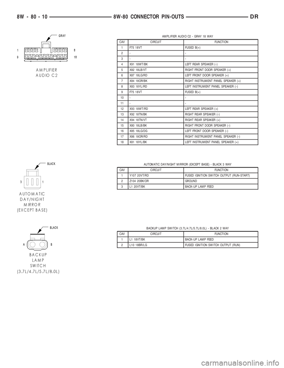
AMPLIFIER AUDIO C2 - GRAY 18 WAY
CAV CIRCUIT FUNCTION
1 F75 18VT FUSED B(+)
2- -
3- -
4 X91 18WT/BK LEFT REAR SPEAKER (-)
5 X82 18LB/VT RIGHT FRONT DOOR SPEAKER (+)
6 X87 18LG/RD LEFT FRONT DOOR SPEAKER (+)
7 X84 18OR/BK RIGHT INSTRUMENT PANEL SPEAKER (+)
8 X83 18YL/RD LEFT INSTRUMENT PANEL SPEAKER (-)
9 F75 18VT FUSED B(+)
10 - -
11 - -
12 X93 18WT/RD LEFT REAR SPEAKER (+)
13 X92 18TN/BK RIGHT REAR SPEAKER (-)
14 X94 18TN/VT RIGHT REAR SPEAKER (+)
15 X80 18LB/BK RIGHT FRONT DOOR SPEAKER (-)
16 X85 18LG/DG LEFT FRONT DOOR SPEAKER (-)
17 X86 18OR/RD RIGHT INSTRUMENT PANEL SPEAKER (-)
18 X81 18YL/BK LEFT INSTRUMENT PANEL SPEAKER (+)
AUTOMATIC DAY/NIGHT MIRROR (EXCEPT BASE) - BLACK 3 WAY
CAV CIRCUIT FUNCTION
1 Y107 20VT/RD FUSED IGNITION SWITCH OUTPUT (RUN-START)
2 Z104 20BK/OR GROUND
3 L1 20VT/BK BACK-UP LAMP FEED
BACKUP LAMP SWITCH (3.7L/4.7L/5.7L/8.0L) - BLACK 2 WAY
CAV CIRCUIT FUNCTION
1 L1 18VT/BK BACK-UP LAMP FEED
2 L10 18BR/LG FUSED IGNITION SWITCH OUTPUT (RUN)
8W - 80 - 10 8W-80 CONNECTOR PIN-OUTSDR
Page 1120 of 2895
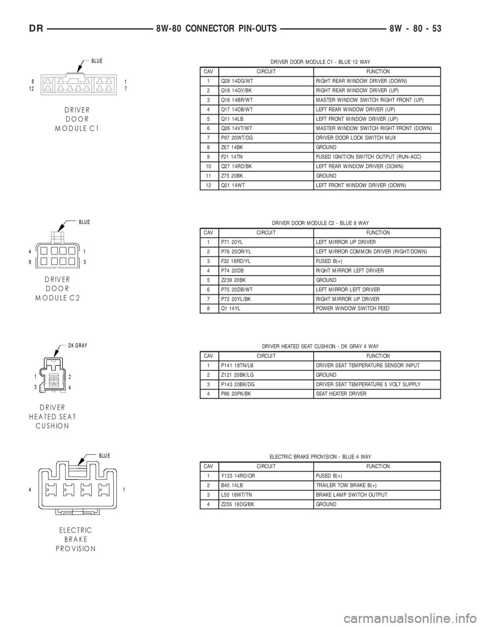
DRIVER DOOR MODULE C1 - BLUE 12 WAY
CAV CIRCUIT FUNCTION
1 Q28 14DG/WT RIGHT REAR WINDOW DRIVER (DOWN)
2 Q18 14GY/BK RIGHT REAR WINDOW DRIVER (UP)
3 Q16 14BR/WT MASTER WINDOW SWITCH RIGHT FRONT (UP)
4 Q17 14DB/WT LEFT REAR WINDOW DRIVER (UP)
5 Q11 14LB LEFT FRONT WINDOW DRIVER (UP)
6 Q26 14VT/WT MASTER WINDOW SWITCH RIGHT FRONT (DOWN)
7 P97 20WT/DG DRIVER DOOR LOCK SWITCH MUX
8 Z67 14BK GROUND
9 F21 14TN FUSED IGNITION SWITCH OUTPUT (RUN-ACC)
10 Q27 14RD/BK LEFT REAR WINDOW DRIVER (DOWN)
11 Z75 20BK GROUND
12 Q21 14WT LEFT FRONT WINDOW DRIVER (DOWN)
DRIVER DOOR MODULE C2 - BLUE 8 WAY
CAV CIRCUIT FUNCTION
1 P71 20YL LEFT MIRROR UP DRIVER
2 P76 20OR/YL LEFT MIRROR COMMON DRIVER (RIGHT/DOWN)
3 F32 18RD/YL FUSED B(+)
4 P74 20DB RIGHT MIRROR LEFT DRIVER
5 Z239 20BK GROUND
6 P75 20DB/WT LEFT MIRROR LEFT DRIVER
7 P72 20YL/BK RIGHT MIRROR UP DRIVER
8 Q1 14YL POWER WINDOW SWITCH FEED
DRIVER HEATED SEAT CUSHION - DK GRAY 4 WAY
CAV CIRCUIT FUNCTION
1 P141 18TN/LB DRIVER SEAT TEMPERATURE SENSOR INPUT
2 Z121 20BK/LG GROUND
3 P143 20BK/DG DRIVER SEAT TEMPERATURE 5 VOLT SUPPLY
4 P86 20PK/BK SEAT HEATER DRIVER
ELECTRIC BRAKE PROVISION - BLUE 4 WAY
CAV CIRCUIT FUNCTION
1 Y133 14RD/OR FUSED B(+)
2 B40 14LB TRAILER TOW BRAKE B(+)
3 L50 18WT/TN BRAKE LAMP SWITCH OUTPUT
4 Z255 18DG/BK GROUND
DR8W-80 CONNECTOR PIN-OUTS 8W - 80 - 53
Page 1139 of 2895
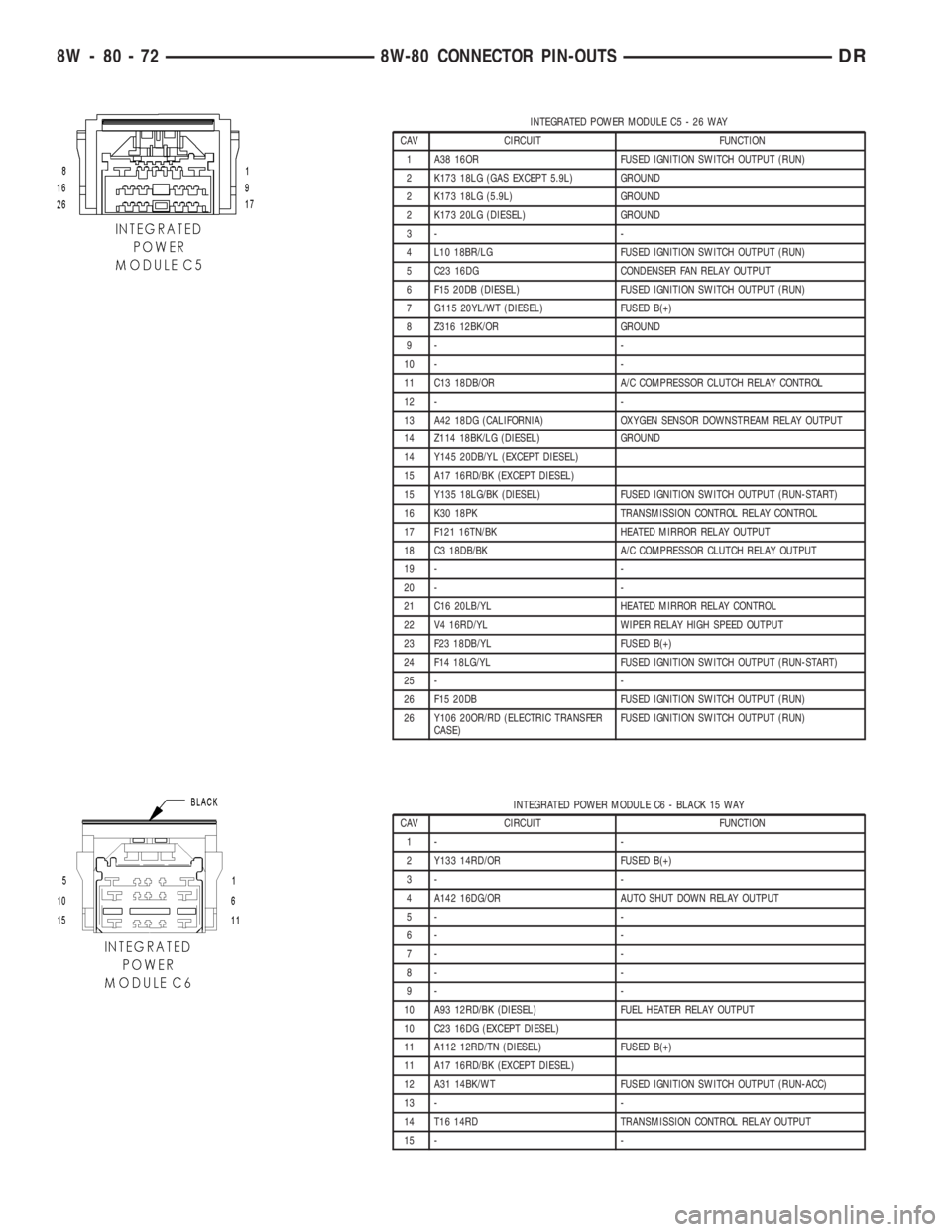
INTEGRATED POWER MODULE C5 - 26 WAY
CAV CIRCUIT FUNCTION
1 A38 16OR FUSED IGNITION SWITCH OUTPUT (RUN)
2 K173 18LG (GAS EXCEPT 5.9L) GROUND
2 K173 18LG (5.9L) GROUND
2 K173 20LG (DIESEL) GROUND
3- -
4 L10 18BR/LG FUSED IGNITION SWITCH OUTPUT (RUN)
5 C23 16DG CONDENSER FAN RELAY OUTPUT
6 F15 20DB (DIESEL) FUSED IGNITION SWITCH OUTPUT (RUN)
7 G115 20YL/WT (DIESEL) FUSED B(+)
8 Z316 12BK/OR GROUND
9- -
10 - -
11 C13 18DB/OR A/C COMPRESSOR CLUTCH RELAY CONTROL
12 - -
13 A42 18DG (CALIFORNIA) OXYGEN SENSOR DOWNSTREAM RELAY OUTPUT
14 Z114 18BK/LG (DIESEL) GROUND
14 Y145 20DB/YL (EXCEPT DIESEL)
15 A17 16RD/BK (EXCEPT DIESEL)
15 Y135 18LG/BK (DIESEL) FUSED IGNITION SWITCH OUTPUT (RUN-START)
16 K30 18PK TRANSMISSION CONTROL RELAY CONTROL
17 F121 16TN/BK HEATED MIRROR RELAY OUTPUT
18 C3 18DB/BK A/C COMPRESSOR CLUTCH RELAY OUTPUT
19 - -
20 - -
21 C16 20LB/YL HEATED MIRROR RELAY CONTROL
22 V4 16RD/YL WIPER RELAY HIGH SPEED OUTPUT
23 F23 18DB/YL FUSED B(+)
24 F14 18LG/YL FUSED IGNITION SWITCH OUTPUT (RUN-START)
25 - -
26 F15 20DB FUSED IGNITION SWITCH OUTPUT (RUN)
26 Y106 20OR/RD (ELECTRIC TRANSFER
CASE)FUSED IGNITION SWITCH OUTPUT (RUN)
INTEGRATED POWER MODULE C6 - BLACK 15 WAY
CAV CIRCUIT FUNCTION
1- -
2 Y133 14RD/OR FUSED B(+)
3- -
4 A142 16DG/OR AUTO SHUT DOWN RELAY OUTPUT
5- -
6- -
7- -
8- -
9- -
10 A93 12RD/BK (DIESEL) FUEL HEATER RELAY OUTPUT
10 C23 16DG (EXCEPT DIESEL)
11 A112 12RD/TN (DIESEL) FUSED B(+)
11 A17 16RD/BK (EXCEPT DIESEL)
12 A31 14BK/WT FUSED IGNITION SWITCH OUTPUT (RUN-ACC)
13 - -
14 T16 14RD TRANSMISSION CONTROL RELAY OUTPUT
15 - -
8W - 80 - 72 8W-80 CONNECTOR PIN-OUTSDR
Page 1147 of 2895
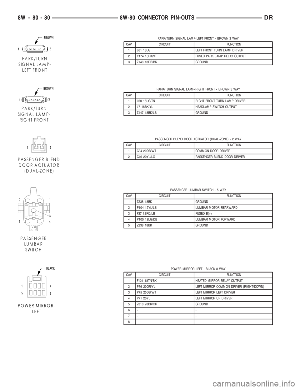
PARK/TURN SIGNAL LAMP-LEFT FRONT - BROWN 3 WAY
CAV CIRCUIT FUNCTION
1 L61 18LG LEFT FRONT TURN LAMP DRIVER
2 Y174 18PK/VT FUSED PARK LAMP RELAY OUTPUT
3 Z148 18DB/BK GROUND
PARK/TURN SIGNAL LAMP-RIGHT FRONT - BROWN 3 WAY
CAV CIRCUIT FUNCTION
1 L60 18LG/TN RIGHT FRONT TURN LAMP DRIVER
2 L7 18BK/YL HEADLAMP SWITCH OUTPUT
3 Z147 18BK/LB GROUND
PASSENGER BLEND DOOR ACTUATOR (DUAL-ZONE)-2WAY
CAV CIRCUIT FUNCTION
1 C34 20DB/WT COMMON DOOR DRIVER
2 C46 20YL/LG PASSENGER BLEND DOOR DRIVER
PASSENGER LUMBAR SWITCH-5WAY
CAV CIRCUIT FUNCTION
1 Z238 18BK GROUND
2 P104 12YL/LB LUMBAR MOTOR REARWARD
3 F37 12RD/LB FUSED B(+)
4 P105 12LG/DB LUMBAR MOTOR FORWARD
5 Z238 18BK GROUND
POWER MIRROR-LEFT - BLACK 8 WAY
CAV CIRCUIT FUNCTION
1 F121 18TN/BK HEATED MIRROR RELAY OUTPUT
2 P76 20OR/YL LEFT MIRROR COMMON DRIVER (RIGHT/DOWN)
3 P75 20DB/WT LEFT MIRROR LEFT DRIVER
4 P71 20YL LEFT MIRROR UP DRIVER
5 Z310 20BK/OR GROUND
6- -
7- -
8- -
8W - 80 - 80 8W-80 CONNECTOR PIN-OUTSDR
Page 1148 of 2895
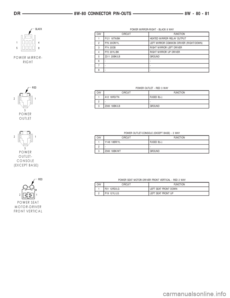
POWER MIRROR-RIGHT - BLACK 8 WAY
CAV CIRCUIT FUNCTION
1 F121 18TN/BK HEATED MIRROR RELAY OUTPUT
2 P76 20OR/YL LEFT MIRROR COMMON DRIVER (RIGHT/DOWN)
3 P74 20DB RIGHT MIRROR LEFT DRIVER
4 P72 20YL/BK RIGHT MIRROR UP DRIVER
5 Z311 20BK/LB GROUND
6- -
7- -
8- -
POWER OUTLET - RED 3 WAY
CAV CIRCUIT FUNCTION
1 A12 18RD/TN FUSED B(+)
2- -
3 Z300 18BK/LB GROUND
POWER OUTLET-CONSOLE (EXCEPT BASE)-3WAY
CAV CIRCUIT FUNCTION
1 Y148 18BR/YL FUSED B(+)
2- -
3 Z300 18BK/WT GROUND
POWER SEAT MOTOR-DRIVER FRONT VERTICAL - RED 2 WAY
CAV CIRCUIT FUNCTION
1 P21 12RD/LG LEFT SEAT FRONT DOWN
2 P19 12YL/LG LEFT SEAT FRONT UP
DR8W-80 CONNECTOR PIN-OUTS 8W - 80 - 81
Page 1178 of 2895
8W-91 CONNECTOR/GROUND/SPLICE LOCATION
TABLE OF CONTENTS
page
CONNECTOR/GROUND/SPLICE LOCATION
DESCRIPTION..........................1
CONNECTOR/GROUND/SPLICE
LOCATION
DESCRIPTION
This section provides illustrations identifying con-
nector, ground, and splice locations in the vehicle.
Connector, ground, and splice indexes are provided.Use the wiring diagrams in each section for connec-
tor, ground, and splice identification. Refer to the
index for the proper figure number. For items that
are not shown in this section N/S is placed in the
Fig. column.
CONNECTORS
CONNECTOR NAME/NUMBER COLOR LOCATION FIG.
4WD Switch (Manual Transfer
Case)BK Near T/O for Backup Lamp Switch 16
A/C Compressor Clutch BK At A/C Compressor 3, 5, 8, 9, 10
A/C Pressure Transducer BK Left Side of A/C Compressor 3, 5, 8, 9, 10
A/C-Heater Control C1 BK Center of Instrument Panel 36, 37, 38
A/C-Heater Control C2 BK Center of Instrument Panel 36, 37
Adjustable Pedal Motor WT Left of Instrument Panel 33
Adjustable Pedal Switch BL Left of Instrument Panel 37, 39
Airbag Control Module YL Lower Center of Instrument Panel 37, 38
Airbag Control Module-Left Side
ImpactYL Left B-Pillar 44, 45
Airbag Control Module-Right Side
ImpactYL Right B-Pillar N/S
Airbag-Driver Squib 1 YL On Steering Wheel 32
Airbag-Left Curtain Squib YL Top Left B-Pillar 44, 45
Airbag-Passenger Squib 1 YL Right Front of Instrument Panel 37, 40
Airbag-Right Curtain Squib YL Top Right B-Pillar N/S
Ambient Temperature Sensor BK Left Rear of Hood 31
Amplifier Audio C1 GY Top Center of Instrument Panel 37, 40
Amplifier Audio C2 GY Top Center of Instrument Panel 37, 40
Automatic Day/Night Mirror (Except
Base)BK Top Center of Windshield N/S
Backup Lamp Switch BK Left Rear of Transmission 16
Battery Temperature Sensor BK Below Battery Tray 26, 28, 29, 30
Blend Door Actuator (Single Zone) BK Behind Right Side of Instrument
PanelN/S
DR8W-91 CONNECTOR/GROUND/SPLICE LOCATION 8W - 91 - 1
Page 1183 of 2895
CONNECTOR NAME/NUMBER COLOR LOCATION FIG.
Manifold Absolute Pressure Sensor
(5.9L)BK Left Front of Intake Manifold 8
Mode Door Actuator 1 BK Right Side of HVAC N/S
Mode Door Actuator 2 BK Right Side of HVAC N/S
Multi-Function Switch BK On Steering Column N/S
Natural Vacuum Leak Detection
AssemblyBK Rear of Transmission 18, 19
Output Speed Sensor DB Left Side of Transmission 11, 12, 14, 15
Overdrive Switch WT Center of Instrument Panel 37
Overhead Map/Reading Lamp
(Except Base)NAT Center of Headliner N/S
Oxygen Sensor 1/1 Upstream BK Left Front of Side of Transmission 11, 12, 14, 16
Oxygen Sensor 1/2 Downstream NAT Left Rear of Side of Transmission 11, 14, 16
Oxygen Sensor 2/1 Upstream BK Right Front Side of Transmission 11, 12, 14, 16, 17, 18,
19
Oxygen Sensor 2/2 Downstream BK Right Rear Side of Transmission 11, 12, 14, 16, 17, 18,
19
Park Brake Switch At Park Brake 26, 27
Park/Turn Signal Lamp-Left Front BK At Lamp 26, 30, 31
Park/Turn Signal Lamp-Right Front BK At Lamp 1, 25, 29
Passenger Airbag On/Off Switch Right Side of Instrument Panel 35, 37, 40
Passenger Blend Door Actuator
(Dual Zone)BK Right Side of HVAC N/S
Passenger Lumbar Switch At Passenger Seat N/S
Power Mirror-Left BK At Mirror 42
Power Mirror-Right BK At Mirror N/S
Power Outlet RD Center of Instrument Panel 37
Power Outlet-Console BK Center of Instrument Panel N/S
Power Seat Motor-Driver Front
VerticalRD At Driver Seat N/S
Power Seat Motor-Driver Horizontal BK At Driver Seat N/S
Power Seat Motor-Driver Rear
VerticalBK At Driver Seat N/S
Power Seat Switch-Driver BK At Driver Seat N/S
Power Seat Switch-Passenger BK At Passenger Seat N/S
Power Steering Pressure Switch BK Near Power Steering Pump 4, 5
Power Window Circuit Breaker Under Instrument Panel 33, 37, 39
Power Window Motor-Driver BK In Driver Door at Motor 42
Power Window Motor-Left Rear BK In Door at Motor 43
Power Window Motor-Passenger BK In Passenger Door at Motor N/S
Power Window Motor-Right Rear BK In Door at Motor 43
Power Window Switch-Left Rear BL In Door 43
Power Window Switch-Right Rear BL In Door 43
Powertrain Control Module C1 BK Right Rear Engine Compartment 21, 22, 23, 24
8W - 91 - 6 8W-91 CONNECTOR/GROUND/SPLICE LOCATIONDR
CONNECTOR/GROUND/SPLICE LOCATION (Continued)
Page 1325 of 2895
The idler shaft is a light press-fit into the cylinder
block. A large washer on the idler shaft bolt and the
rear flange of the idler shaft are used to control
sprocket thrust movement. Pressurized oil is routed
through the center of the idler shaft to provide lubri-
cation for the two bushings used in the idler sprocket
assembly.
There are two secondary drive chains, both are
roller type, one to drive the camshaft in each SOHC
cylinder head. There are no shaft speed changes in
the secondary chain drive system. Each secondary
chain drives a 26 tooth cam sprocket directly from
the 26 tooth sprocket on the idler sprocket assembly.
A fixed chain guide and a hydraulic oil damped ten-
sioner are used to maintain tension in each second-
ary chain system. The hydraulic tensioners for the
secondary chain systems are fed pressurized oil from
oil reservoir pockets in the block. Each tensioner
incorporates a controlled leak path through a device
known as a vent disc located in the nose of the piston
to manage chain loads. Each tensioner also has a
mechanical ratchet system that limits chain slack if
the tensioner piston bleeds down after engine shut
down. The tensioner arms and guides also utilize
nylon wear faces for low friction and long wear. The
secondary timing chains receive lubrication from a
small orifice in the tensioners. This orifice is pro-
tected from clogging by a fine mesh screen which is
located on the back of the hydraulic tensioners.
STANDARD PROCEDURE
MEASURING TIMING CHAIN WEAR
NOTE: This procedure must be performed with the
timing chain cover removed.
(1) Remove the timing chain cover. Refer to Timing
Chain Cover in this section for procedure.
(2) To determine if the secondary timing chains
are worn, rotate the engine clockwise until maximum
tensioner piston extension is obtained. Measure the
distance between the secondary timing chain ten-
sioner housing and the step ledge on the piston. The
measurement at point (A) must be less than 15mm
(.5906 inches).
(3) If the measurement exceeds the specification
the secondary timing chains are worn and require
replacement. Refer to Timing Chain and Sprockets in
this section for procedure.
SERVICE PROCEDURE - TIMING VERIFICATION
CAUTION: The 3.7L is a non free-wheeling design
engine. Therefore, correct engine timing is critical.NOTE: Components referred to as left hand or right
hand are as viewed from the drivers position inside
the vehicle.
NOTE: The blue link plates on the chains and the
dots on the camshaft drive sprockets may not line
up during the timing verification procedure. The
blue link plates are lined up with the sprocket dots
only when re-timing the complete timing drive.
Once the timing drive is rotated blue link-to-dot
alignment is no longer valid.
Engine base timing can be verified by the following
procedure:
(1) Remove the cylinder head covers. Refer to the
procedure in this section.
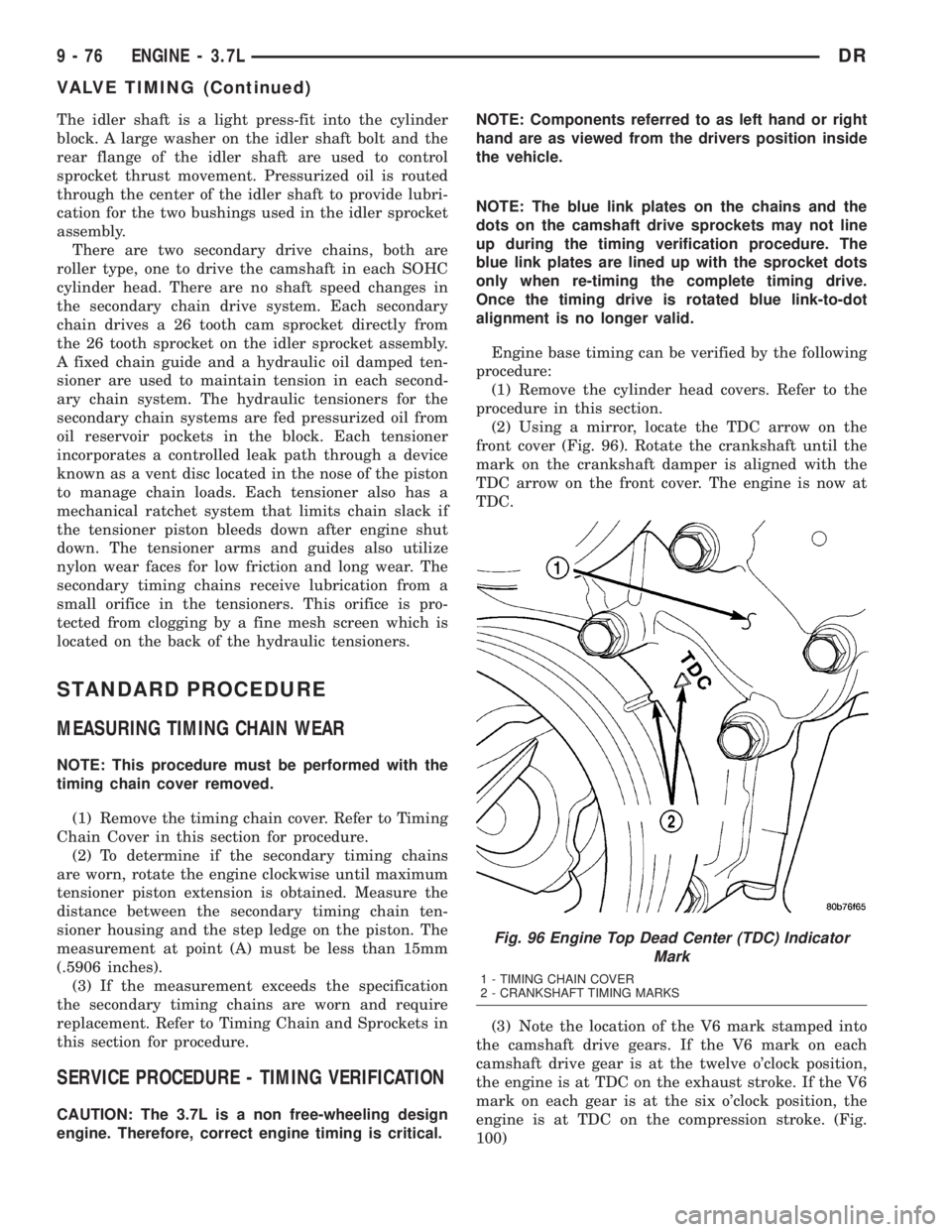
(2) Using a mirror, locate the TDC arrow on the
front cover (Fig. 96). Rotate the crankshaft until the
mark on the crankshaft damper is aligned with the
TDC arrow on the front cover. The engine is now at
TDC.
(3) Note the location of the V6 mark stamped into
the camshaft drive gears. If the V6 mark on each
camshaft drive gear is at the twelve o'clock position,
the engine is at TDC on the exhaust stroke. If the V6
mark on each gear is at the six o'clock position, the
engine is at TDC on the compression stroke. (Fig.
100)
Fig. 96 Engine Top Dead Center (TDC) Indicator
Mark
1 - TIMING CHAIN COVER
2 - CRANKSHAFT TIMING MARKS
9 - 76 ENGINE - 3.7LDR
VALVE TIMING (Continued)