2003 DODGE RAM Spark plug
[x] Cancel search: Spark plugPage 486 of 2895

mal in condition and can be cleaned using standard
procedures.
CHIPPED ELECTRODE INSULATOR
A chipped electrode insulator usually results from
bending the center electrode while adjusting the
spark plug electrode gap. Under certain conditions,
severe detonation can also separate the insulator
from the center electrode (Fig. 46). Spark plugs with
this condition must be replaced.
PREIGNITION DAMAGE
Preignition damage is usually caused by excessive
combustion chamber temperature. The center elec-
trode dissolves first and the ground electrode dis-
solves somewhat latter (Fig. 47). Insulators appear
relatively deposit free. Determine if the spark plug
has the correct heat range rating for the engine.Determine if ignition timing is over advanced or if
other operating conditions are causing engine over-
heating. (The heat range rating refers to the operat-
ing temperature of a particular type spark plug.
Spark plugs are designed to operate within specific
temperature ranges. This depends upon the thick-
ness and length of the center electrodes porcelain
insulator.)
SPARK PLUG OVERHEATING
Overheating is indicated by a white or gray center
electrode insulator that also appears blistered (Fig.
48). The increase in electrode gap will be consider-
ably in excess of 0.001 inch per 2000 miles of opera-
tion. This suggests that a plug with a cooler heat
range rating should be used. Over advanced ignition
timing, detonation and cooling system malfunctions
can also cause spark plug overheating.
Fig. 45 SCAVENGER DEPOSITS
1 - GROUND ELECTRODE COVERED WITH WHITE OR YELLOW
DEPOSITS
2 - CENTER ELECTRODE
Fig. 46 CHIPPED ELECTRODE INSULATOR
1 - GROUND ELECTRODE
2 - CENTER ELECTRODE
3 - CHIPPED INSULATOR
Fig. 47 PREIGNITION DAMAGE
1 - GROUND ELECTRODE STARTING TO DISSOLVE
2 - CENTER ELECTRODE DISSOLVED
Fig. 48 SPARK PLUG OVERHEATING
1 - BLISTERED WHITE OR GRAY COLORED INSULATOR
DRIGNITION CONTROL 8I - 29
SPARK PLUG (Continued)
Page 487 of 2895

REMOVAL
3.7L V-6
Each individual spark plug is located under each
ignition coil. Each individual ignition coil must be
removed to gain access to each spark plug. Refer to
Ignition Coil Removal/Installation.
(1) Remove necessary air filter tubing at throttle
body.
(2) Prior to removing ignition coil, spray com-
pressed air around coil base at cylinder head.
(3) Prior to removing spark plug, spray com-
pressed air into cylinder head opening. This will help
prevent foreign material from entering combustion
chamber.
(4) Remove spark plug from cylinder head using a
quality socket with a rubber or foam insert. Also
check condition of ignition coil o-ring and replace as
necessary.
(5) Inspect spark plug condition. Refer to Diagnos-
tics and Testing - Spark Plug Conditions.
4.7L V-8
Each individual spark plug is located under each
ignition coil. Each individual ignition coil must be
removed to gain access to each spark plug. Refer to
Ignition Coil Removal/Installation.
(1) Remove necessary air filter tubing at throttle
body.
(2) Prior to removing ignition coil, spray com-
pressed air around coil base at cylinder head.
(3) Prior to removing spark plug, spray com-
pressed air into cylinder head opening. This will help
prevent foreign material from entering combustion
chamber.
(4) Remove spark plug from cylinder head using a
quality socket with a rubber or foam insert. Also
check condition of ignition coil o-ring and replace as
necessary.
(5) Inspect spark plug condition. Refer to Diagnos-
tics and Testing - Spark Plug Conditions.
5.7L V-8
Eight of the 16 spark plugs are located under an
ignition coil; the other 8 are not. If spark plug being
removed is under coil, coil must be removed to gain
access to spark plug. Refer to Ignition Coil Removal/
Installation and observe all CAUTIONS and WARN-
INGS.
Before removing or disconnecting any spark plug
cables, note their original position. Remove cables
one-at-a-time. To prevent ignition crossfire, spark
plug cablesMUSTbe placed in cable tray (routing
loom) into their original position. Refer to Spark Plug
Cable Removal for a graphic.Before installing spark plug cables to either the
spark plugs or coils, apply dielectric grease to inside
of boots.
(1) Remove necessary air filter tubing at throttle
body.
(2) Prior to removing ignition coil (if coil removal
is necessary), spray compressed air around coil base
at cylinder head cover.
(3) Prior to removing spark plug, spray com-
pressed air into cylinder head opening. This will help
prevent foreign material from entering combustion
chamber.
(4) Remove spark plug from cylinder head using a
quality socket with a rubber or foam insert.
(5) Inspect spark plug condition. Refer to Diagnos-
tics and Testing - Spark Plug Conditions.
5.9L V-8
On 5.9L V-8 engines, spark plug cable heat shields
are pressed into the cylinder head to surround each
cable boot and spark plug (Fig. 49).
(1) Always remove spark plug or ignition coil
cables by grasping at the cable boot (Fig. 50). Turn
the cable boot 1/2 turn and pull straight back in a
steady motion. Never pull directly on the cable.
Internal damage to cable will result.
(2) Prior to removing the spark plug, spray com-
pressed air around the spark plug hole and the area
around the spark plug. This will help prevent foreign
material from entering the combustion chamber.
(3) Remove the spark plug using a quality socket
with a rubber or foam insert.
(4) Inspect the spark plug condition. Refer to Diag-
nostics and Testing - Spark Plug Conditions.
Fig. 49 HEAT SHIELDS - 5.9L V-8
1 - AIR GAP
2 - SPARK PLUG BOOT HEAT SHIELD
8I - 30 IGNITION CONTROLDR
SPARK PLUG (Continued)
Page 488 of 2895

8.0L V-10
(1) Always remove spark plug or ignition coil
cables by grasping at the cable boot (Fig. 50). Turn
the cable boot 1/2 turn and pull straight back in a
steady motion. Never pull directly on the cable.
Internal damage to cable will result.
(2) Prior to removing the spark plug, spray com-
pressed air around the spark plug hole and the area
around the spark plug. This will help prevent foreign
material from entering the combustion chamber.
(3) Remove the spark plug using a quality socket
with a rubber or foam insert.
(4) Inspect the spark plug condition. Refer to Diag-
nostics and Testing - Spark Plug Conditions.
CLEANING
CLEANING AND ADJUSTMENT
The plugs may be cleaned using commercially
available spark plug cleaning equipment. After clean-
ing, file center electrode flat with a small point file or
jewelers file before adjusting gap.
CAUTION: Never use a motorized wire wheel brush
to clean spark plugs. Metallic deposits will remain
on spark plug insulator and will cause plug misfire.
Adjust spark plug gap with a gap gauging tool
(Fig. 51).
INSTALLATION
3.7L V-6
Special care should be taken when installing spark
plugs into the cylinder head spark plug wells. Be
sure the plugs do not drop into the plug wells as elec-
trodes can be damaged.
Always tighten spark plugs to the specified torque.
Over tightening can cause distortion resulting in a
change in the spark plug gap or a cracked porcelain
insulator.
(1) Start the spark plug into the cylinder head by
hand to avoid cross threading.
(2) Tighten spark plugs. Refer to torque specifica-
tions.
(3) Before installing ignition coil(s), check condi-
tion of coil o-ring and replace as necessary. To aid in
coil installation, apply silicone to coil o-ring.
(4) Install ignition coil(s). Refer to Ignition Coil
Removal/Installation.
Fig. 50 CABLE REMOVAL - 5.9L / 8.0L
1 - SPARK PLUG CABLE AND BOOT
2 - SPARK PLUG BOOT PULLER
3 - TWIST AND PULL
4 - SPARK PLUG
Fig. 51 SETTING SPARK PLUG GAP - TYPICAL
1 - GAUGE TOOL
2 - SPARK PLUG
DRIGNITION CONTROL 8I - 31
SPARK PLUG (Continued)
Page 489 of 2895

4.7L V-8
CAUTION: The 4.7L V±8 engine is equipped with
copper core ground electrode spark plugs. They
must be replaced with the same type/number spark
plug as the original. If another spark plug is substi-
tuted, pre-ignition will result.
Special care should be taken when installing spark
plugs into the cylinder head spark plug wells. Be
sure the plugs do not drop into the plug wells as elec-
trodes can be damaged.
Always tighten spark plugs to the specified torque.
Over tightening can cause distortion resulting in a
change in the spark plug gap or a cracked porcelain
insulator.
(1) Start the spark plug into the cylinder head by
hand to avoid cross threading.
(2) Tighten spark plugs. Refer to torque specifica-
tions.
(3) Before installing ignition coil(s), check condi-
tion of coil o-ring and replace as necessary. To aid in
coil installation, apply silicone to coil o-ring.
(4) Install ignition coil(s). Refer to Ignition Coil
Removal/Installation.
5.7L V-8
(1) Special care should be taken when installing
spark plugs into the cylinder head spark plug wells.
Be sure the plugs do not drop into the plug wells as
electrodes can be damaged.
(2) Start the spark plug into cylinder head by
hand to avoid cross threading aluminum threads. To
aid in installation, attach a piece of rubber hose, or
an old spark plug boot to spark plug.
(3) The 5.7L V-8 is equipped with torque critical
design spark plugs. Do not exceed 15 ft. lbs. torque.
Tighten spark plugs. Refer to torque specifications.
(4) Before installing spark plug cables to either the
spark plugs or coils, apply dielectric grease to inside
of boots.
(5) To prevent ignition crossfire, spark plug cables
MUSTbe placed in cable tray (routing loom) into
their original position. Refer to Spark Plug Cable
Removal for a graphic.
(6) Install ignition coil(s) to necessary spark plugs.
Refer to Ignition Coil Installation.
(7) Install spark plug cables to remaining spark
plugs. Remember to apply dielectric grease to inside
of boots.
5.9L V-8
Special care should be taken when installing spark
plugs into the cylinder head spark plug wells. Be
sure the plugs do not drop into the plug wells as elec-
trodes can be damaged.
Always tighten spark plugs to the specified torque.
Over tightening can cause distortion resulting in a
change in the spark plug gap or a cracked porcelain
insulator.
When replacing the spark plug and ignition coil
cables, route the cables correctly and secure them in
the appropriate retainers. Failure to route the cables
properly can cause the radio to reproduce ignition
noise. It could cause cross ignition of the spark plugs
or short circuit the cables to ground.
(1) Start the spark plug into the cylinder head by
hand to avoid cross threading.
(2) Tighten spark plugs. Refer to torque specifica-
tions.
(3) Install spark plug cables to spark plugs. On
5.9L V-8 engines, spark plug cable heat shields are
pressed into the cylinder head to surround each
spark plug cable boot and spark plug (Fig. 53). These
shields protect the spark plug boots from damage
(due to intense engine heat generated by the exhaust
manifolds) and should not be removed. After the
spark plug cable has been installed, the lip of the
cable boot should have a small air gap to the top of
the heat shield (Fig. 53).
8.0L V-10
Special care should be taken when installing spark
plugs into the cylinder head spark plug wells. Be
sure the plugs do not drop into the plug wells as elec-
trodes can be damaged.
Always tighten spark plugs to the specified torque.
Over tightening can cause distortion resulting in a
change in the spark plug gap or a cracked porcelain
insulator.
When replacing the spark plug and ignition coil
cables, route the cables correctly and secure them in
the appropriate retainers. Failure to route the cables
properly can cause the radio to reproduce ignition
noise. It could cause cross ignition of the spark plugs
or short circuit the cables to ground.
(1) Start the spark plug into the cylinder head by
hand to avoid cross threading.
(2) Tighten spark plugs. Refer to torque specifica-
tions.
(3) Install spark plug cables to spark plugs.
8I - 32 IGNITION CONTROLDR
SPARK PLUG (Continued)
Page 490 of 2895

IGNITION COIL CAPACITOR
DESCRIPTION
One coil capacitor is used. It is located in the right-
rear section of the engine compartment.
OPERATION
The coil capacitor(s) help dampen the amount of
conducted electrical noise to the camshaft position
sensor, crankshaft position sensor, and throttle posi-
tion sensor. This noise is generated on the 12V sup-
ply wire to the ignition coils and fuel injectors.
REMOVAL
The coil capacitor is located in the right-rear sec-
tion of the engine compartment. It is attached with a
mounting stud and nut.
(1) Disconnect electrical connector at capacitor
(Fig. 52).
(2) Remove mounting nut and remove ground
strap.
(3) Remove capacitor.
INSTALLATION
(1) Position capacitor to mounting stud.
(2) Position ground strap to mounting stud.
(3) Tighten nut to 7 N´m (60 in. lbs.) torque.
(4) Connect electrical connector to coil capacitor.
SPARK PLUG CABLE
DESCRIPTION
Spark plug cables are sometimes referred to as sec-
ondary ignition wires, or secondary ignition cables.
Plug cables are used only on the 5.7L V-8, 5.9L V-8
and 8.0L V-10 engines.
OPERATION
The spark plug cables transfer electrical current
from the ignition coil(s) and/or distributor, to individ-
ual spark plugs at each cylinder. The resistive spark
plug cables are of nonmetallic construction. The
cables provide suppression of radio frequency emis-
sions from the ignition system.
Plug cables are used only on the 5.7L V-8, 5.9L V-8
and 8.0L V-10 engines.
DIAGNOSIS AND TESTING - SPARK PLUG
CABLES
Cable routing is important on certain engines. To
prevent possible ignition crossfire, be sure the cables
are clipped into the plastic routing looms. Refer to
Spark Plug Cable Removal for addditional informa-
tion. Try to prevent any one cable from contacting
another. Before removing cables, note their original
location and routing. Never allow one cable to be
twisted around another.
Check the spark plug cable connections for good
contact at the coil(s), distributor cap towers (if appli-
caple), and spark plugs. Terminals should be fully
seated. The insulators should be in good condition
and should fit tightly on the coil, distributor and
spark plugs. Spark plug cables with insulators that
are cracked or torn must be replaced.
Clean high voltage ignition cables with a cloth
moistened with a non-flammable solvent. Wipe the
cables dry. Check for brittle or cracked insulation.
On 5.9L V-8 engines, spark plug cable heat shields
are pressed into the cylinder head to surround each
spark plug cable boot and spark plug (Fig. 53). These
shields protect the spark plug boots from damage
(due to intense engine heat generated by the exhaust
manifolds) and should not be removed. After the
spark plug cable has been installed, the lip of the
cable boot should have a small air gap to the top of
the heat shield (Fig. 53).
TESTING
When testing secondary cables for damage with an
oscilloscope, follow the instructions of the equipment
manufacturer.
If an oscilloscope is not available, spark plug cables
may be tested as follows:
Fig. 52 CAPACITOR LOCATION
1 - COIL CAPACITOR
2 - MOUNTING STUD
3 - GROUND STRAP
4 - MOUNTING NUT
5 - ELEC. CONNECT.
DRIGNITION CONTROL 8I - 33
Page 491 of 2895
CAUTION: Do not leave any one spark plug cable
disconnected for longer than necessary during test-
ing. This may cause possible heat damage to the
catalytic converter. Total test time must not exceed
ten minutes.
Except 5.7L V-8 :With the engine running,
remove spark plug cable from spark plug (one at a
time) and hold next to a good engine ground. If the
cable and spark plug are in good condition, the
engine rpm should drop and the engine will run
poorly. If engine rpm does not drop, the cable and/or
spark plug may not be operating properly and should
be replaced. Also check engine cylinder compression.
With the engine not running, connect one end of a
test probe to a good ground. Start the engine and run
the other end of the test probe along the entire
length of all spark plug cables. If cables are cracked
or punctured, there will be a noticeable spark jump
from the damaged area to the test probe. The cable
running from the ignition coil to the distributor cap
can be checked in the same manner. Cracked, dam-
aged or faulty cables should be replaced with resis-
tance type cable. This can be identified by the words
ELECTRONIC SUPPRESSION printed on the cable
jacket.Use an ohmmeter to test for open circuits, exces-
sive resistance or loose terminals. If equipped,
remove the distributor cap from the distributor.Do
not remove cables from cap.Remove cable from
spark plug. Connect ohmmeter to spark plug termi-
nal end of cable and to corresponding electrode in
distributor cap. Resistance should be 250 to 1000
Ohms per inch of cable. If not, remove cable from dis-
tributor cap tower and connect ohmmeter to the ter-
minal ends of cable. If resistance is not within
specifications as found in the SPARK PLUG CABLE
RESISTANCE chart, replace the cable. Test all spark
plug cables in this manner.
SPARK PLUG CABLE RESISTANCE
MINIMUM MAXIMUM
250 Ohms Per Inch 1000 Ohms Per Inch
3000 Ohms Per Foot 12,000 Ohms Per Foot
To test ignition coil-to-distributor cap cable (if
applicaple), do not remove the cable from the cap.
Connect ohmmeter to rotor button (center contact) of
distributor cap and terminal at ignition coil end of
cable. If resistance is not within specifications as
found in the Spark Plug Cable Resistance chart,
remove the cable from the distributor cap. Connect
the ohmmeter to the terminal ends of the cable. If
resistance is not within specifications as found in the
Spark Plug Cable Resistance chart, replace the cable.
Inspect the ignition coil tower for cracks, burns or
corrosion.
REMOVAL
5.9L V-8 / 8.0L V-10
CAUTION: When disconnecting a high voltage cable
from a spark plug or from the distributor cap, twist
the rubber boot slightly (1/2 turn) to break it loose
(Fig. 54). Grasp the boot (not the cable) and pull it
off with a steady, even force.
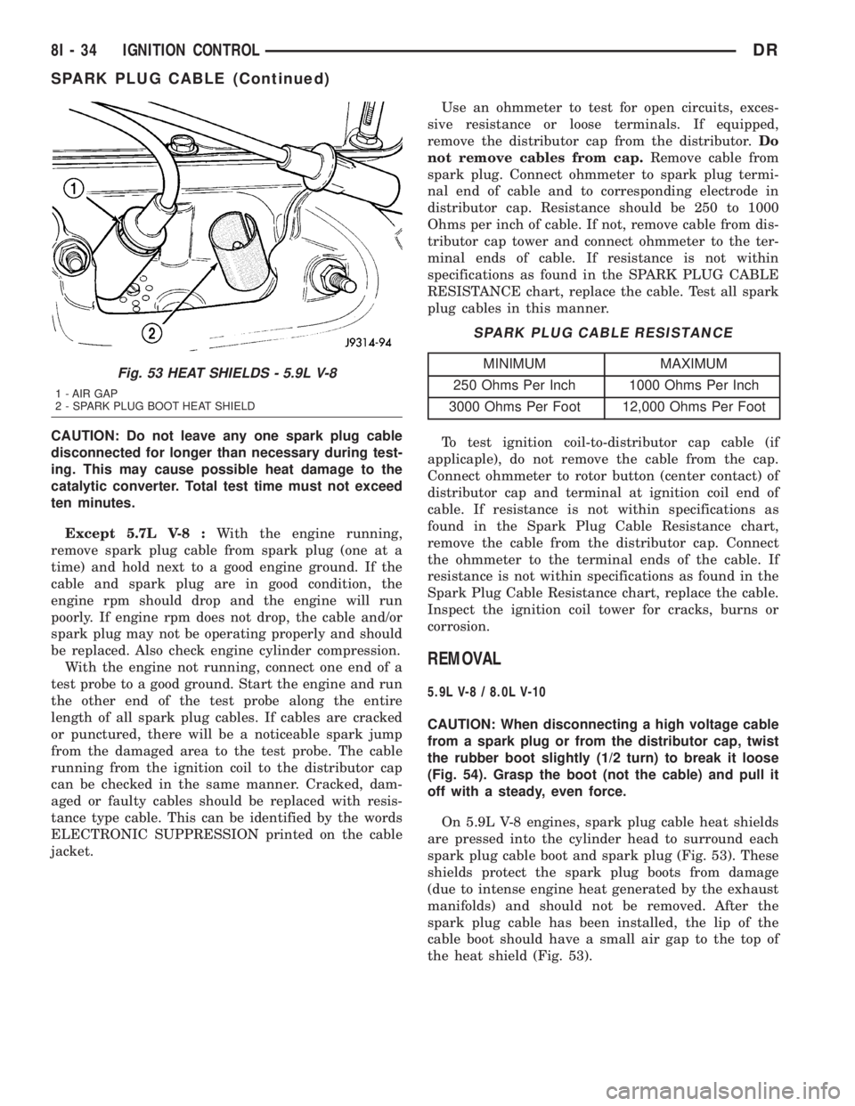
On 5.9L V-8 engines, spark plug cable heat shields
are pressed into the cylinder head to surround each
spark plug cable boot and spark plug (Fig. 53). These
shields protect the spark plug boots from damage
(due to intense engine heat generated by the exhaust
manifolds) and should not be removed. After the
spark plug cable has been installed, the lip of the
cable boot should have a small air gap to the top of
the heat shield (Fig. 53).
Fig. 53 HEAT SHIELDS - 5.9L V-8
1 - AIR GAP
2 - SPARK PLUG BOOT HEAT SHIELD
8I - 34 IGNITION CONTROLDR
SPARK PLUG CABLE (Continued)
Page 492 of 2895
5.7L V-8
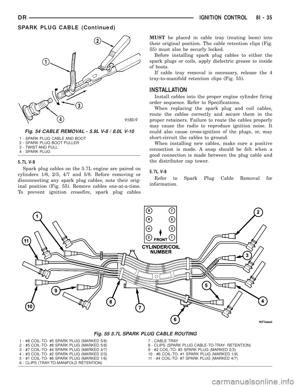
Spark plug cables on the 5.7L engine are paired on
cylinders 1/6, 2/3, 4/7 and 5/8. Before removing or
disconnecting any spark plug cables, note their orig-
inal position (Fig. 55). Remove cables one-at-a-time.
To prevent ignition crossfire, spark plug cablesMUSTbe placed in cable tray (routing loom) into
their original position. The cable retention clips (Fig.
55) must also be securly locked.
Before installing spark plug cables to either the
spark plugs or coils, apply dielectric grease to inside
of boots.
If cable tray removal is necessary, release the 4
tray-to-manifold retention clips (Fig. 55).
INSTALLATION
Install cables into the proper engine cylinder firing
order sequence. Refer to Specifications.
When replacing the spark plug and coil cables,
route the cables correctly and secure them in the
proper retainers. Failure to route the cables properly
may cause the radio to reproduce ignition noise. It
could also cause cross-ignition of the plugs, or, may
short-circuit the cables to ground.
When installing new cables, make sure a positive
connection is made. A snap should be felt when a
good connection is made between the plug cable and
the distributor cap tower.
5.7L V-8
Refer to Spark Plug Cable Removal for
information.
Fig. 55 5.7L SPARK PLUG CABLE ROUTING
1 - #8 COIL-TO- #5 SPARK PLUG (MARKED 5/8) 7 - CABLE TRAY
2 - #5 COIL-TO- #8 SPARK PLUG (MARKED 5/8) 8 - CLIPS (SPARK PLUG CABLE-TO-TRAY- RETENTION)
3 - #7 COIL-TO- #4 SPARK PLUG (MARKED 4/7) 9 - #2 COIL-TO- #3 SPARK PLUG (MARKED 2/3)
4 - #3 COIL-TO- #2 SPARK PLUG (MARKED 2/3) 10 - #6 COIL-TO- #1 SPARK PLUG (MARKED 1/6)
5 - #1 COIL-TO- #6 SPARK PLUG (MARKED 1/6) 11 - #4 COIL-TO- #7 SPARK PLUG (MARKED 4/7)
6 - CLIPS (TRAY-TO-MANIFOLD RETENTION)
Fig. 54 CABLE REMOVAL - 5.9L V-8 / 8.0L V-10
1 - SPARK PLUG CABLE AND BOOT
2 - SPARK PLUG BOOT PULLER
3 - TWIST AND PULL
4 - SPARK PLUG
DRIGNITION CONTROL 8I - 35
SPARK PLUG CABLE (Continued)
Page 1253 of 2895
DIAGNOSIS AND TESTING
DIAGNOSIS AND TESTING - ENGINE
DIAGNOSIS - INTRODUCTION
Engine diagnosis is helpful in determining the
causes of malfunctions not detected and remedied by
routine maintenance.
These malfunctions may be classified as either per-
formance (e.g., engine idles rough and stalls) or
mechanical (e.g., a strange noise).
(Refer to 9 - ENGINE - DIAGNOSIS AND TEST-
ING)ÐPERFORMANCE and (Refer to 9 - ENGINE -
DIAGNOSIS AND TESTING)ÐMECHANICAL for
possible causes and corrections of malfunctions.
(Refer to 14 - FUEL SYSTEM/FUEL DELIVERY -
DIAGNOSIS AND TESTING) and (Refer to 14 -
FUEL SYSTEM/FUEL INJECTION - DIAGNOSIS
AND TESTING) for the fuel system diagnosis.Additional tests and diagnostic procedures may be
necessary for specific engine malfunctions that can
not be isolated with the Service Diagnosis charts.
Information concerning additional tests and diagno-
sis is provided within the following diagnosis:
²Cylinder Compression Pressure Test (Refer to 9 -
ENGINE - DIAGNOSIS AND TESTING).
²Cylinder Combustion Pressure Leakage Test
(Refer to 9 - ENGINE - DIAGNOSIS AND TEST-
ING).
²Engine Cylinder Head Gasket Failure Diagnosis
(Refer to 9 - ENGINE/CYLINDER HEAD - DIAGNO-
SIS AND TESTING).
²Intake Manifold Leakage Diagnosis (Refer to 9 -
ENGINE/MANIFOLDS/INTAKE MANIFOLD -
DIAGNOSIS AND TESTING).
DIAGNOSIS AND TESTING - ENGINE DIAGNOSIS - PERFORMANCE
CONDITION POSSIBLE CAUSE CORRECTION
ENGINE WILL NOT START 1. Weak battery 1. Charge or replace as necessary.
2. Corroded or loose battery
connections.2. Clean and tighten battery
connections. Apply a coat of light
mineral grease to the terminals.
3. Faulty starter. 3. (Refer to 8 - ELECTRICAL/
STARTING - DIAGNOSIS AND
TESTING).
4. Faulty coil or control unit. 4. (Refer to 8 - ELECTRICAL/
IGNITION CONTROL/IGNITION
COIL - REMOVAL).
5. Incorrect spark plug gap. 5. (Refer to 8 - ELECTRICAL/
IGNITION CONTROL/SPARK PLUG
- CLEANING).
6. Incorrect right bank cam timing. 6. Refer to engine timing in this
section.
7. Dirt or water in fuel system. 7. Clean system and replace fuel
filter.
8.Faulty fuel pump, relay or wiring. 8.Repair or replace as necessary.
9. Faulty cam or crank sensor 9. Refer to Ignition system.
ENGINE STALLS OR ROUGH IDLE 1. Vacuum leak. 1. Inspect intake manifold and
vacuum hoses, repair or replace as
necessary.
2. Faulty crank position sensor 2. Replace crank position sensor.
3. Faulty coil. 3. (Refer to 8 - ELECTRICAL/
IGNITION CONTROL/IGNITION
COIL - REMOVAL).
9 - 4 ENGINE - 3.7LDR
ENGINE - 3.7L (Continued)