2003 DODGE RAM Oil pump
[x] Cancel search: Oil pumpPage 2810 of 2895
erant system. Refer to the operating instructions sup-
plied by the equipment manufacturer for the proper
care and use of this equipment.
STANDARD PROCEDURE - REFRIGERANT
SYSTEM EVACUATE
WARNING: REVIEW THE WARNINGS AND CAU-
TIONS IN THE FRONT OF THIS SECTION BEFORE
PERFORMING THE FOLLOWING OPERATION.
(Refer to 24 - HEATING & AIR CONDITIONING/
PLUMBING - WARNING) (Refer to 24 - HEATING &
AIR CONDITIONING/PLUMBING - CAUTION)
If the refrigerant system has been open to the
atmosphere, it must be evacuated before the system
can be charged. If moisture and air enters the system
and becomes mixed with the refrigerant, the com-
pressor head pressure will rise above acceptable
operating levels. This will reduce the performance of
the air conditioner and damage the compressor.
Evacuating the refrigerant system will remove the
air and boil the moisture out of the system at near
room temperature. To evacuate the refrigerant sys-
tem, use the following procedure:
(1) Connect a R-134a refrigerant recovery/recy-
cling/charging station that meets SAE Standard
J2210 and a manifold gauge set to the refrigerant
system of the vehicle.
(2) Recover the refrigerant(Refer to 24 - HEATING
& AIR CONDITIONING/PLUMBING - STANDARD
PROCEDURE).
(3) Open the low and high side valves and start
the charging station vacuum pump. When the suc-
tion gauge reads 88 kPa (26 in. Hg.) vacuum or
greater, close all of the valves and turn off the vac-
uum pump.
(a) If the refrigerant system fails to reach the
specified vacuum, the system has a leak that must
be corrected. (Refer to 24 - HEATING & AIR CON-
DITIONING/PLUMBING - DIAGNOSIS AND
TESTING - REFRIGERANT SYSTEM LEAKS)
(b) If the refrigerant system maintains the spec-
ified vacuum for five minutes, restart the vacuum
pump, open the suction and discharge valves and
evacuate the system for an additional ten minutes.
(4) Close all of the valves, and turn off the charg-
ing station vacuum pump.
(5) The refrigerant system is now ready to be
charged with R-134a refrigerant. (Refer to 24 -
HEATING & AIR CONDITIONING/PLUMBING -
STANDARD PROCEDURE - REFRIGERANT SYS-
TEM CHARGE)
STANDARD PROCEDURE - REFRIGERANT
SYSTEM CHARGE
WARNING: REVIEW THE WARNINGS AND CAU-
TIONS IN THE FRONT OF THIS SECTION BEFORE
PERFORMING THE FOLLOWING OPERATION.
(Refer to 24 - HEATING & AIR CONDITIONING/
PLUMBING - WARNING) (Refer to 24 - HEATING &
AIR CONDITIONING/PLUMBING - CAUTION)
After the refrigerant system has been tested for
leaks and evacuated, a refrigerant charge can be
injected into the system. (Refer to 24 - HEATING &
AIR CONDITIONING/PLUMBING - SPECIFICA-
TIONS - CHARGE CAPACITY)
A R-134a refrigerant recovery/recycling/charging
station that meets SAE Standard J2210 must be
used to charge the refrigerant system with R-134a
refrigerant. Refer to the operating instructions sup-
plied by the equipment manufacturer for proper care
and use of this equipment.
The R-134a refrigerant charge capacity for this
vehicle is 0.7371 Kg (26 oz.).
NOTE: Always refer to the HVAC underhood sticker
for current refrigerant charge level and refrigerant
oil specifications.
SPECIFICATIONS - CHARGE CAPACITY
The R-134a refrigerant system charge capacity for
this vehicle is: 0.7371 Kg. (26 oz.).
A/C COMPRESSOR
DESCRIPTION
DESCRIPTION
The air conditioning system uses a Sanden SD-7
reciprocating swash plate-type compressor on all
models. This compressor has a fixed displacement of
165 cubic centimeter and has both the suction and
discharge ports located on the cylinder head. A label
identifying the use of R-134a refrigerant is located on
the compressor.
DESCRIPTION - HIGH PRESSURE RELIEF
VALVE
A high pressure relief valve is located on the com-
pressor cylinder head, which is on the rear of the
compressor. This mechanical valve is designed to
vent refrigerant from the system to protect against
damage to the compressor and other system compo-
DRPLUMBING 24 - 35
PLUMBING (Continued)
Page 2811 of 2895
nents, caused by condenser air flow restriction or an
overcharge of refrigerant.
OPERATION
OPERATION
The compressor is driven by the engine through an
electric clutch, drive rotor and belt arrangement. The
compressor is lubricated by refrigerant oil that is cir-
culated throughout the refrigerant system with the
refrigerant.
The compressor draws in low-pressure refrigerant
vapor from the evaporator through its suction port. It
then compresses the refrigerant into a high-pressure,
high-temperature refrigerant vapor, which is then
pumped to the condenser through the compressor dis-
charge port.
The compressor cannot be repaired. If faulty or
damaged, the entire compressor assembly must be
replaced. The compressor clutch, pulley and clutch
coil are available for service.
OPERATION - HIGH PRESSURE RELIEF VALVE
The high pressure relief valve vents the system
when a discharge pressure of 3445 to 4135 kPa (500
to 600 psi) or above is reached. The valve closes
when a minimum discharge pressure of 2756 kPa
(400 psi) is reached.
The high pressure relief valve vents only enough
refrigerant to reduce the system pressure, and then
re-seats itself. The majority of the refrigerant is con-
served in the system. If the valve vents refrigerant, it
does not mean that the valve is faulty.
The high pressure relief valve is a factory-cali-
brated unit. The valve cannot be adjusted or
repaired, and must not be removed or otherwise dis-
turbed. The valve is only serviced as a part of the
compressor assembly.
DIAGNOSIS AND TESTING - A/C COMPRESSOR
NOISE
When investigating an air conditioning related
noise, you must first know the conditions under
which the noise occurs. These conditions include:
weather, vehicle speed, transmission in gear or neu-
tral, engine speed, engine temperature, and any
other special conditions. Noises that develop during
air conditioning operation can often be misleading.
For example: What sounds like a failed front bearing
or connecting rod, may be caused by loose bolts, nuts,
mounting brackets, or a loose compressor clutch
assembly.
Drive belts are speed sensitive. At different engine
speeds and depending upon belt tension, belts can
develop noises that are mistaken for a compressornoise. Improper belt tension can cause a misleading
noise when the compressor clutch is engaged, which
may not occur when the compressor clutch is disen-
gaged. Check the serpentine drive belt condition and
tension as described in Cooling before beginning this
procedure.
(1) Select a quiet area for testing. Duplicate the
complaint conditions as much as possible. Switch the
compressor on and off several times to clearly iden-
tify the compressor noise. Listen to the compressor
while the clutch is engaged and disengaged. Probe
the compressor with an engine stethoscope or a long
screwdriver with the handle held to your ear to bet-
ter localize the source of the noise.
(2) Loosen all of the compressor mounting hard-
ware and retighten. Tighten the compressor clutch
mounting nut. Be certain that the clutch coil is
mounted securely to the compressor, and that the
clutch plate and rotor are properly aligned and have
the correct air gap. (Refer to 24 - HEATING & AIR
CONDITIONING/CONTROLS/A/C COMPRESSOR
CLUTCH - INSTALLATION)
(3) To duplicate a high-ambient temperature condi-
tion (high head pressure), restrict the air flow
through the condenser. Install a manifold gauge set
to be certain that the discharge pressure does not
exceed 2760 kPa (400 psi).
(4) Check the refrigerant system plumbing for
incorrect routing, rubbing or interference, which can
cause unusual noises. Also check the refrigerant lines
for kinks or sharp bends that will restrict refrigerant
flow, which can cause noises. (Refer to 24 - HEAT-
ING & AIR CONDITIONING/PLUMBING - CAU-
TION)
(5) If the noise is from opening and closing of the
high pressure relief valve, evacuate and recharge the
refrigerant system. (Refer to 24 - HEATING & AIR
CONDITIONING/PLUMBING - STANDARD PRO-
CEDURE - REFRIGERANT SYSTEM EVACUATE)
(Refer to 24 - HEATING & AIR CONDITIONING/
PLUMBING - STANDARD PROCEDURE - REFRIG-
ERANT SYSTEM CHARGE) If the high pressure
relief valve still does not seat properly, replace the
compressor.
(6) If the noise is from liquid slugging on the suc-
tion line. Check the refrigerant oil level and the
refrigerant system charge. (Refer to 24 - HEATING
& AIR CONDITIONING/PLUMBING/REFRIGER-
ANT OIL - STANDARD PROCEDURE) (Refer to 24 -
HEATING & AIR CONDITIONING/PLUMBING -
SPECIFICATIONS - CHARGE CAPACITY) If either
is out of specification range reclaim, evacuate and
recharge the refrigerent system(Refer to 24 - HEAT-
ING & AIR CONDITIONING/PLUMBING/REFRIG-
ERANT - STANDARD PROCEDURE), (Refer to 24 -
HEATING & AIR CONDITIONING/PLUMBING/RE-
24 - 36 PLUMBINGDR
A/C COMPRESSOR (Continued)
Page 2827 of 2895
air and boil the moisture out of the system at near
room temperature. To evacuate the refrigerant sys-
tem, use the following procedure:
(1) Connect a R-134a refrigerant recovery/recy-
cling/charging station that meets SAE Standard
J2210 and a manifold gauge set (if required) to the
refrigerant system of the vehicle and recover refrig-
erant.
(2) Open the low and high side valves and start
the charging station vacuum pump. When the suc-
tion gauge reads 88 kPa (26 in. Hg.) vacuum or
greater, close all of the valves and turn off the vac-
uum pump.
(a) If the refrigerant system fails to reach the
specified vacuum, the system has a leak that must
be corrected. See Refrigerant System Leaks in the
Diagnosis and Testing section of this group for the
procedures.
(b) If the refrigerant system maintains the spec-
ified vacuum for five minutes, restart the vacuum
pump, open the suction and discharge valves and
evacuate the system for an additional ten minutes.
(3) Close all of the valves, and turn off the charg-
ing station vacuum pump.
(4) The refrigerant system is now ready to be
charged with R-134a refrigerant(Refer to 24 - HEAT-
ING & AIR CONDITIONING/PLUMBING/REFRIG-
ERANT - STANDARD PROCEDURE).
STANDARD PROCEDURE- REFRIGERANT
RECOVERY
WARNING: (Refer to 24 - HEATING & AIR CONDI-
TIONING/PLUMBING - WARNING) AND (Refer to 24 -
HEATING & AIR CONDITIONING/PLUMBING - CAU-
TION) BEFORE PERFORMING THE FOLLOWING
OPERATION.
A R-134a refrigerant recovery/recycling/charging
station that meets SAE Standard J2210 must be
used to recover the refrigerant from an R-134a refrig-
erant system. Refer to the operating instructions sup-
plied by the equipment manufacturer for the proper
care and use of this equipment.
STANDARD PROCEDURE- REFRIGERANT
SYSTEM CHARGE
WARNING: (Refer to 24 - HEATING & AIR CONDI-
TIONING/PLUMBING - WARNING) AND (Refer to 24 -
HEATING & AIR CONDITIONING/PLUMBING - CAU-
TION) BEFORE PERFORMING THE FOLLOWING
OPERATION.
After the refrigerant system has been tested for
leaks and evacuated, a refrigerant charge can beinjected into the system. See Refrigerant Charge
Capacity in the Service Procedures section of this
group for the proper amount of the refrigerant
charge, this fill level can also be found on a label
attached under the hood of the vehicle..
A R-134a refrigerant recovery/recycling/charging
station that meets SAE Standard J2210 must be
used to charge the refrigerant system with R-134a
refrigerant. Refer to the operating instructions sup-
plied by the equipment manufacturer for the proper
care and use of this equipment.
The R-134a refrigerant system charge capacity for
this vehicle is:
²If equipped with a 3.7L or a 4.7L engine charge
to 0.6804 Kg. (24 oz.).
²If equipped with a 5.9L engine charge to 0.7371
Kg. ( 26 oz.).
REFRIGERANT LINE COUPLER
DESCRIPTION
Spring-lock type refrigerant line couplers are used
to connect many of the refrigerant lines and other
components to the refrigerant system. These couplers
require a special tool for disengaging the two coupler
halves.
OPERATION
The spring-lock coupler is held together by a garter
spring inside a circular cage on the male half of the
fitting (Fig. 16). When the two coupler halves are
connected, the flared end of the female fitting slips
behind the garter spring inside the cage on the male
fitting. The garter spring and cage prevent the flared
end of the female fitting from pulling out of the cage.
Three O-rings on the male half of the fitting are
used to seal the connection. These O-rings are com-
patible with R-134a refrigerant and must be replaced
with O-rings made of the same material.
Secondary clips are installed over the two con-
nected coupler halves at the factory for added blowoff
protection.
REMOVAL
WARNING: (Refer to 24 - HEATING & AIR CONDI-
TIONING/PLUMBING - WARNING) (Refer to 24 -
HEATING & AIR CONDITIONING/PLUMBING - CAU-
TION) BEFORE PERFORMING THE FOLLOWING
OPERATION.
(1) Recover the refrigerant from the refrigerant
system(Refer to 24 - HEATING & AIR CONDITION-
ING/PLUMBING/REFRIGERANT - STANDARD
PROCEDURE).
24 - 52 PLUMBINGDR
REFRIGERANT (Continued)
Page 2837 of 2895
²Upstream O2S VoltsÐ A live reading of the
Oxygen Sensor to indicate its performance. For
example, stuck lean, stuck rich, etc.
²SCW Time in Window (Similar Conditions
Window Time in Window)Ð A timer used by the
PCM that indicates that, after all Similar Conditions
have been met, if there has been enough good engine
running time in the SCW without failure detected.
This timer is used to increment a Good Trip.
²Fuel System Good Trip CounterÐATrip
Counter used to turn OFF the MIL for Fuel System
DTCs. To increment a Fuel System Good Trip, the
engine must be in the Similar Conditions Window,
Adaptive Memory Factor must be less than cali-
brated threshold and the Adaptive Memory Factor
must stay below that threshold for a calibrated
amount of time.
²Test Done This TripÐ Indicates that the
monitor has already been run and completed during
the current trip.
MISFIRE
²Same Misfire Warm-Up StateÐ Indicates if
the misfire occurred when the engine was warmed up
(above 160É F).
²In Similar Misfire WindowÐ An indicator
that 'Absolute MAP When Misfire Occurred' and
'RPM When Misfire Occurred' are all in the same
range when the failure occurred. Indicated by switch-
ing from 'NO' to 'YES'.
²Absolute MAP When Misfire OccurredÐ
The stored MAP reading at the time of failure.
Informs the user at what engine load the failure
occurred.
²Absolute MAPÐ A live reading of engine load
to aid the user in accessing the Similar Conditions
Window.
²RPM When Misfire OccurredÐ The stored
RPM reading at the time of failure. Informs the user
at what engine RPM the failure occurred.
²Engine RPMÐ A live reading of engine RPM
to aid the user in accessing the Similar Conditions
Window.
²Adaptive Memory FactorÐ The PCM utilizes
both Short Term Compensation and Long Term Adap-
tive to calculate the Adaptive Memory Factor for
total fuel correction.
²200 Rev CounterÐ Counts 0±100 720 degree
cycles.
²SCW Cat 200 Rev CounterÐ Counts when in
similar conditions.
²SCW FTP 1000 Rev CounterÐ Counts 0±4
when in similar conditions.
²Misfire Good Trip CounterÐ Counts up to
three to turn OFF the MIL.
²Misfire DataÐ Data collected during test.²Test Done This TripÐ Indicates YES when the
test is done.
OPERATION - NON-MONITORED CIRCUITS
The PCM does not monitor the following circuits,
systems and conditions that could have malfunctions
causing driveability problems. The PCM might not
store diagnostic trouble codes for these conditions.
However, problems with these systems may cause the
PCM to store diagnostic trouble codes for other sys-
tems or components.EXAMPLE:a fuel pressure
problem will not register a fault directly, but could
cause a rich/lean condition or misfire. This could
cause the PCM to store an oxygen sensor or misfire
diagnostic trouble code
FUEL PRESSURE
The fuel pressure regulator controls fuel system
pressure. The PCM cannot detect a clogged fuel
pump inlet filter, clogged in-line fuel filter, or a
pinched fuel supply or return line. However, these
could result in a rich or lean condition causing the
PCM to store an oxygen sensor or fuel system diag-
nostic trouble code.
SECONDARY IGNITION CIRCUIT
The PCM cannot detect an inoperative ignition coil,
fouled or worn spark plugs, ignition cross firing, or
open spark plug cables.
CYLINDER COMPRESSION
The PCM cannot detect uneven, low, or high engine
cylinder compression.
EXHAUST SYSTEM
The PCM cannot detect a plugged, restricted or
leaking exhaust system, although it may set a fuel
system fault.
FUEL INJECTOR MECHANICAL MALFUNCTIONS
The PCM cannot determine if a fuel injector is
clogged, the needle is sticking or if the wrong injector
is installed. However, these could result in a rich or
lean condition causing the PCM to store a diagnostic
trouble code for either misfire, an oxygen sensor, or
the fuel system.
EXCESSIVE OIL CONSUMPTION
Although the PCM monitors engine exhaust oxygen
content when the system is in closed loop, it cannot
determine excessive oil consumption.
THROTTLE BODY AIR FLOW
The PCM cannot detect a clogged or restricted air
cleaner inlet or filter element.
25 - 8 EMISSIONS CONTROLDR
EMISSIONS CONTROL (Continued)
Page 2841 of 2895

SPECIFICATIONS
TORQUE - EVAP SYSTEM
DESCRIPTION N´m Ft. Lbs. In. Lbs.
EVAP Canister Mounting
Nuts11 -95
EVAP Canister Mounting
Bracket-to-Frame Bolts14 10125
Leak Detection Pump
Mounting Bolts11 - 9 5
Leak Detection Pump
Filter Mounting Bolt11 - 9 5
CCV HOSE
DESCRIPTION - 8.0L V-10
The 8.0L V-10 engine is equipped with a Crankcase
Ventilation (CCV) system. The CCV system performs
the same function as a conventional PCV system, but
does not use a vacuum controlled valve (PCV valve).
A molded vacuum tube connects manifold vacuum
to the top of the right cylinder head (valve) cover.
The vacuum tube connects to a fixed orifice fitting
(Fig. 2) of a calibrated size 2.6 mm (0.10 inches).
OPERATION - 8.0L V-10
A molded vacuum tube connects manifold vacuum
to the top of the right cylinder head (valve) cover.
The vacuum tube connects to a fixed orifice fitting
(Fig. 2) of a calibrated size 2.6 mm (0.10 inches). Thefitting meters the amount of crankcase vapors drawn
out of the engine.The fixed orifice fitting is grey
in color.A similar fitting (but does not contain a
fixed orifice) is used on the left cylinder head (valve)
cover. This fitting is black in color. Do not inter-
change these two fittings.
When the engine is operating, fresh air enters the
engine and mixes with crankcase vapors. Manifold
vacuum draws the vapor/air mixture through the
fixed orifice and into the intake manifold. The vapors
are then consumed during engine combustion.
EVAP/PURGE SOLENOID
DESCRIPTION
The duty cycle EVAP canister purge solenoid is
located in the engine compartment. It is attached to
the side of the Power Distribution Center (PDC).
OPERATION
The Powertrain Control Module (PCM) operates
the solenoid.
During the cold start warm-up period and the hot
start time delay, the PCM does not energize the sole-
noid. When de-energized, no vapors are purged. The
PCM de-energizes the solenoid during open loop oper-
ation.
The engine enters closed loop operation after it
reaches a specified temperature and the time delay
ends. During closed loop operation, the PCM ener-
gizes and de-energizes the solenoid 5 or 10 times per
second, depending upon operating conditions. The
PCM varies the vapor flow rate by changing solenoid
pulse width. Pulse width is the amount of time the
solenoid energizes. The PCM adjusts solenoid pulse
width based on engine operating condition.
Fig. 2 FIXED ORIFICE FITTING - 8.0L V-10 ENGINE -
TYPICAL
1 - VACUUM TUBE
2 - FIXED ORIFICE FITTING
3 - COIL PACKS
4 - ORIFICE FITTING HOSE CONNECTIONS
25 - 12 EVAPORATIVE EMISSIONSDR
EVAPORATIVE EMISSIONS (Continued)
Page 2845 of 2895
REMOVAL
The Leak Detection Pump (LDP) and LDP filter
are attached to the front of the EVAP canister
mounting bracket (Fig. 9). This is located near the
front of the fuel tank. The LDP and LDP filter are
replaced (serviced) as one unit.
(1) Raise and support vehicle.
(2) Carefully remove hose at LDP filter.
(3) Remove LDP filter mounting bolt and remove
from vehicle.
(4) Carefully remove vapor/vacuum lines at LDP.
(5) Disconnect electrical connector at LDP.
(6) Remove LDP mounting bolt and remove LDP
from vehicle.
INSTALLATION
The LDP and LDP filter are attached to the front
of the EVAP canister mounting bracket. The LDP
and LDP filter are replaced (serviced) as one unit.
(1) Install LDP to mounting bracket. Refer to
Torque Specifications.
(2) Install LDP filter to mounting bracket. Refer to
Torque Specifications.
(3) Carefully install vapor/vacuum lines to LDP,
and install hose to LDP filter.The vapor/vacuum
lines and hoses must be firmly connected.
Check the vapor/vacuum lines at the LDP, LDPfilter and EVAP canister purge solenoid for
damage or leaks. If a leak is present, a Diagnos-
tic Trouble Code (DTC) may be set.
(4) Connect electrical connector to LDP.
PCV VALVE
DESCRIPTION
3.7L V-6 / 4.7L V-8
The 3.7L V-6 and 4.7L V-8 engines are equipped
with a closed crankcase ventilation system and a
Positive Crankcase Ventilation (PCV) valve.
This system consists of:
²a PCV valve mounted to the oil filler housing
(Fig. 10). The PCV valve is sealed to the oil filler
housing with an o-ring.
²the air cleaner housing
²two interconnected breathers threaded into the
rear of each cylinder head (Fig. 11).
²tubes and hoses to connect the system compo-
nents.
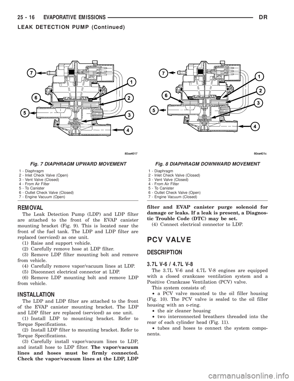
Fig. 7 DIAPHRAGM UPWARD MOVEMENT
1 - Diaphragm
2 - Inlet Check Valve (Open)
3 - Vent Valve (Closed)
4 - From Air Filter
5 - To Canister
6 - Outlet Check Valve (Closed)
7 - Engine Vacuum (Open)
Fig. 8 DIAPHRAGM DOWNWARD MOVEMENT
1 - Diaphragm
2 - Inlet Check Valve (Closed)
3 - Vent Valve (Closed)
4 - From Air Filter
5 - To Canister
6 - Outlet Check Valve (Open)
7 - Engine Vacuum (Closed)
25 - 16 EVAPORATIVE EMISSIONSDR
LEAK DETECTION PUMP (Continued)
Page 2856 of 2895
ABS - DESCRIPTION, BRAKES...........5-39
ABS - OPERATION, BRAKES.............5-39
ABS BRAKE BLEEDING - STANDARD
PROCEDURE.........................5-40
ABS INDICATOR - DESCRIPTION.........8J-17
ABS INDICATOR - OPERATION..........8J-17
A/C APPLICATION TABLE,
SPECIFICATIONS......................24-7
A/C COMPRESSOR CLUTCH -
DESCRIPTION........................24-9
A/C COMPRESSOR CLUTCH -
INSPECTION........................24-12
A/C COMPRESSOR CLUTCH -
INSTALLATION.......................24-12
A/C COMPRESSOR CLUTCH -
OPERATION..........................24-9
A/C COMPRESSOR CLUTCH - REMOVAL . . 24-10
A/C COMPRESSOR CLUTCH BREAK-IN -
STANDARD PROCEDURE...............24-10
A/C COMPRESSOR CLUTCH COIL -
DIAGNOSIS AND TESTING.............24-10
A/C COMPRESSOR CLUTCH RELAY -
DESCRIPTION.......................24-13
A/C COMPRESSOR CLUTCH RELAY -
INSTALLATION.......................24-14
A/C COMPRESSOR CLUTCH RELAY -
OPERATION.........................24-13
A/C COMPRESSOR CLUTCH RELAY -
REMOVAL..........................24-14
A/C COMPRESSOR NOISE - DIAGNOSIS
AND TESTING.......................24-36
A/C CONDENSER - DESCRIPTION.........24-39
A/C CONDENSER - OPERATION..........24-39
A/C EVAPORATOR - DESCRIPTION.......24-47
A/C EVAPORATOR - INSTALLATION......24-47
A/C EVAPORATOR - OPERATION.........24-47
A/C EVAPORATOR - REMOVAL..........24-47
A/C HEATER CONTROL - DESCRIPTION . . . 24-14
A/C HEATER CONTROL - INSTALLATION . . . 24-15
A/C HEATER CONTROL - REMOVAL......24-14
A/C ORIFICE TUBE - DESCRIPTION.......24-48
A/C ORIFICE TUBE - INSTALLATION......24-49
A/C ORIFICE TUBE - OPERATION........24-48
A/C ORIFICE TUBE - REMOVAL..........24-49
A/C PERFORMANCE - DIAGNOSIS AND
TESTING............................24-2
A/C PRESSURE TRANSDUCER -
DESCRIPTION.......................24-15
A/C PRESSURE TRANSDUCER -
DIAGNOSIS AND TESTING.............24-15
A/C PRESSURE TRANSDUCER -
INSTALLATION.......................24-16
A/C PRESSURE TRANSDUCER -
OPERATION.........................24-15
A/C PRESSURE TRANSDUCER -
REMOVAL..........................24-16
ACCELERATOR PEDAL - INSTALLATION . . . 14-24
ACCELERATOR PEDAL - REMOVAL.......14-24
ACCELERATOR PEDAL POSITION
SENSOR - DESCRIPTION...............14-25
ACCELERATOR PEDAL POSITION
SENSOR - INSTALLATION..............14-25
ACCELERATOR PEDAL POSITION
SENSOR - OPERATION................14-25
ACCELERATOR PEDAL POSITION
SENSOR - REMOVAL..................14-25
ACCESSORY DRIVE BELT - DIAGNOSIS
AND TESTING................7-25,7-28,7-31
ACCUMULATOR - DESCRIPTION.........24-49
ACCUMULATOR - DESCRIPTION
. . 21-191,21-372
ACCUMULATOR - INSPECTION
. . . 21-192,21-373
ACCUMULATOR - INSTALLATION
........24-50
ACCUMULATOR - OPERATION
..........24-49
ACCUMULATOR - OPERATION
....21-192,21-373
ACCUMULATOR - REMOVAL
............24-49
ACM COVER - INSTALLATION
............8O-9
ACM COVER - REMOVAL
...............8O-9
ACTUATION TEST MODE - DESCRIPTION,
CIRCUIT
.............................25-1
ACTUATOR - DESCRIPTION, BLEND
DOOR
.............................24-16
ACTUATOR - DESCRIPTION, FUEL
CONTROL
..........................14-85
ACTUATOR - DESCRIPTION, MODE
DOOR
.............................24-20
ACTUATOR - DESCRIPTION,
RECIRCULATION DOOR
................24-22ACTUATOR - INSTALLATION, BLEND
DOOR.............................24-17
ACTUATOR - INSTALLATION, FLOOR -
DEFROST DOOR.....................24-20
ACTUATOR - INSTALLATION, FUEL
CONTROL..........................14-85
ACTUATOR - INSTALLATION, INSIDE
HANDLE.......................23-22,23-32
ACTUATOR - INSTALLATION, MODE
DOOR.............................24-22
ACTUATOR - INSTALLATION,
RECIRCULATION DOOR................24-23
ACTUATOR - OPERATION, BLEND DOOR . . 24-16
ACTUATOR - OPERATION, FUEL
CONTROL..........................14-85
ACTUATOR - OPERATION, MODE DOOR . . . 24-21
ACTUATOR - OPERATION,
RECIRCULATION DOOR................24-22
ACTUATOR - REMOVAL, BLEND DOOR....24-17
ACTUATOR - REMOVAL, FLOOR -
DEFROST DOOR.....................24-19
ACTUATOR - REMOVAL, FUEL CONTROL . . 14-85
ACTUATOR - REMOVAL, INSIDE HANDLE . 23-22,
23-31
ACTUATOR - REMOVAL, MODE DOOR....24-21
ACTUATOR - REMOVAL, RECIRCULATION
DOOR.............................24-22
ADAPTER HOUSING SEAL -
INSTALLATION...........21-127,21-539,21-83
ADAPTER HOUSING SEAL - REMOVAL . . 21-127,
21-539,21-83
ADAPTER MOUNT - INSTALLATION, DISC
BRAKE CALIPER......................5-17
ADDING ADDITIONAL COOLANT -
STANDARD PROCEDURE................7-19
ADDITIONAL COOLANT - STANDARD
PROCEDURE, ADDING..................7-19
ADHESIVE LOCATIONS -
SPECIFICATIONS, STRUCTURAL........23-113
ADJUSTABLE PEDAL MOTOR -
DESCRIPTION........................5-24
ADJUSTABLE PEDAL MOTOR -
INSTALLATION........................5-24
ADJUSTABLE PEDAL MOTOR - REMOVAL . . 5-24
ADJUSTABLE PEDAL SWITCH -
INSTALLATION.........................5-6
ADJUSTABLE PEDAL SWITCH -
REMOVAL............................5-6
ADJUSTER - DIAGNOSIS AND TESTING,
HYDRAULIC LASH................9-124,9-31
ADJUSTER - INSTALLATION, SEAT BELT
TURNING LOOP.....................8O-50
ADJUSTER - REMOVAL, SEAT BELT
TURNING LOOP.....................8O-50
ADJUSTER ASSEMBLY - DESCRIPTION,
ROCKER ARM.......................9-124
ADJUSTER ASSEMBLY - INSTALLATION,
ROCKER ARM..................9-124,9-249
ADJUSTER ASSEMBLY - REMOVAL,
ROCKER ARM..................9-124,9-249
ADJUSTER ASSY - CLEANING, ROCKER
ARM
..............................9-310
ADJUSTER ASSY - DESCRIPTION,
ROCKER ARM
.......................9-310
ADJUSTER ASSY - INSPECTION,
ROCKER ARM
.......................9-311
ADJUSTER ASSY - INSTALLATION,
ROCKER ARM
.............9-198,9-312,9-379
ADJUSTER ASSY - REMOVAL, ROCKER
ARM
....................9-198,9-310,9-379
ADJUSTING TOOL - ADJUSTMENT, WITH
. . . 5-36
AFTER A SUPPLEMENTAL RESTRAINT
DEPLOYMENT - STANDARD
PROCEDURE, SERVICE
.................8O-7
AIR CHECKING TRANSMISSION CLUTCH
OPERATION - DIAGNOSIS AND
TESTING
..........................21-494
AIR CLEANER ELEMENT - INSTALLATION
. 9-105,
9-20,9-242,9-298,9-370
AIR CLEANER ELEMENT - REMOVAL
. 9-105,9-20,
9-242,9-297,9-370
AIR CONDITIONER - DESCRIPTION,
HEATER
.............................24-1
AIR CONDITIONER - OPERATION,
HEATER
.............................24-1
AIR CONDITIONING - INSTALLATION,
WATER PUMP BYPASS HOSE WITH
.......7-70AIR CONDITIONING - INSTALLATION,
WATER PUMP BYPASS HOSE
WITHOUT............................7-70
AIR CONDITIONING - REMOVAL, WATER
PUMP BYPASS HOSE WITH.............7-68
AIR CONDITIONING - REMOVAL, WATER
PUMP BYPASS HOSE WITHOUT..........7-69
AIR CONTROL MOTOR - DESCRIPTION,
IDLE...............................14-33
AIR CONTROL MOTOR - INSTALLATION,
IDLE...............................14-35
AIR CONTROL MOTOR - OPERATION,
IDLE...............................14-33
AIR CONTROL MOTOR - REMOVAL, IDLE . . 14-34
AIR COOLER AND PLUMBING -
CLEANING, CHARGE..................11-16
AIR COOLER AND PLUMBING -
DESCRIPTION, CHARGE...............11-15
AIR COOLER AND PLUMBING -
INSPECTION, CHARGE.................11-16
AIR COOLER AND PLUMBING -
INSTALLATION, CHARGE...............11-16
AIR COOLER AND PLUMBING -
OPERATION, CHARGE.................11-15
AIR COOLER AND PLUMBING -
REMOVAL, CHARGE..................11-15
AIR COOLER SYSTEM - LEAKS -
DIAGNOSIS AND TESTING, CHARGE......11-15
AIR DAM - INSTALLATION, FRONT........13-2
AIR DAM - REMOVAL, FRONT...........13-2
AIR HEATER - DESCRIPTION, INTAKE.....14-91
AIR HEATER - INSTALLATION, INTAKE....14-91
AIR HEATER - OPERATION, INTAKE......14-91
AIR HEATER - REMOVAL, INTAKE........14-91
AIR HEATER RELAY - DESCRIPTION,
INTAKE ............................14-92
AIR HEATER RELAY - INSTALLATION,
INTAKE ............................14-93
AIR HEATER RELAY - OPERATION,
INTAKE ............................14-92
AIR HEATER RELAY - REMOVAL, INTAKE . . 14-93
AIR INTAKE SYSTEM - INSTALLATION....9-194
AIR INTAKE SYSTEM - REMOVAL........9-194
AIR TEMPERATURE SENSOR -
DESCRIPTION, INTAKE................14-36
AIR TEMPERATURE SENSOR -
INSTALLATION, INTAKE................14-38
AIR TEMPERATURE SENSOR -
OPERATION, INTAKE..................14-36
AIR TEMPERATURE SENSOR -
REMOVAL, INTAKE...................14-36
AIR TEMPERATURE SENSOR/MAP
SENSOR - DESCRIPTION, INTAKE........14-93
AIR TEMPERATURE SENSOR/MAP
SENSOR - INSTALLATION, INTAKE.......14-94
AIR TEMPERATURE SENSOR/MAP
SENSOR - OPERATION, INTAKE.........14-93
AIR TEMPERATURE SENSOR/MAP
SENSOR - REMOVAL, INTAKE...........14-93
AIR TEMPERATURE SENSOR/PRESSURE
SENSOR - DESCRIPTION, INLET.........14-90
AIR TEMPERATURE SENSOR/PRESSURE
SENSOR - INSTALLATION, INLET........14-90
AIR TEMPERATURE SENSOR/PRESSURE
SENSOR - OPERATION, INLET..........14-90
AIR TEMPERATURE SENSOR/PRESSURE
SENSOR - REMOVAL, INLET............14-90
AIR TESTING TRANSMISSION CLUTCH
AND BAND OPERATION - DIAGNOSIS
AND TESTING................21-143,21-324
AIR TO OIL COOLER - INSTALLATION.....7-75
AIR TO OIL COOLER - REMOVAL.........7-74
AIRBAG - DESCRIPTION, DRIVER........8O-22
AIRBAG - DESCRIPTION, PASSENGER....8O-34
AIRBAG - DESCRIPTION, SIDE CURTAIN . . 8O-51
AIRBAG - INSTALLATION, DRIVER.......8O-24
AIRBAG - INSTALLATION, PASSENGER . . . 8O-37
AIRBAG - INSTALLATION, SIDE CURTAIN . . 8O-53
AIRBAG - OPERATION, DRIVER.........8O-23
AIRBAG - OPERATION, PASSENGER......8O-35
AIRBAG - OPERATION, SIDE CURTAIN....8O-51
AIRBAG - REMOVAL, DRIVER
...........8O-23
AIRBAG - REMOVAL, PASSENGER
.......8O-35
AIRBAG - REMOVAL, SIDE CURTAIN
.....8O-52
AIRBAG CONTROL MODULE -
DESCRIPTION
.......................8O-10
AIRBAG CONTROL MODULE -
DESCRIPTION, SIDE IMPACT
...........8O-53
DRINDEX 1
Description Group-Page Description Group-Page Description Group-Page
Page 2857 of 2895
AIRBAG CONTROL MODULE -
INSTALLATION......................8O-12
AIRBAG CONTROL MODULE -
OPERATION.........................8O-10
AIRBAG CONTROL MODULE -
OPERATION, SIDE IMPACT.............8O-54
AIRBAG CONTROL MODULE - REMOVAL . . 8O-11
AIRBAG INDICATOR - DESCRIPTION......8J-18
AIRBAG INDICATOR - OPERATION.......8J-18
AIRBAG ON/OFF SWITCH -
DESCRIPTION, PASSENGER............8O-38
AIRBAG ON/OFF SWITCH -
INSTALLATION, PASSENGER...........8O-39
AIRBAG ON/OFF SWITCH - OPERATION,
PASSENGER........................8O-38
AIRBAG ON/OFF SWITCH - REMOVAL,
PASSENGER........................8O-39
AJAR INDICATOR - DESCRIPTION, DOOR . . 8J-23
AJAR INDICATOR - OPERATION, DOOR . . . 8J-23
AJAR SWITCH - DESCRIPTION, DOOR....8L-25
AJAR SWITCH - OPERATION, DOOR......8L-25
ALIGNMENT - DESCRIPTION, WHEEL.......2-1
ALIGNMENT - OPERATION, WHEEL........2-2
ALIGNMENT - SPECIAL TOOLS,
HEADLAMP..........................8L-7
ALIGNMENT LINK/COIL SUSPENSION -
STANDARD PROCEDURE.................2-5
ALIGNMENT, SPECIAL TOOLS - WHEEL.....2-7
ALIGNMENT, SPECIFICATIONS............2-6
ALUMINUM THREAD REPAIR -
STANDARD PROCEDURE . . 21-156,21-337,21-495
AMBIENT TEMP SENSOR - DESCRIPTION . 8M-10
AMBIENT TEMP SENSOR - OPERATION . . 8M-10
AMBIENT TEMPERATURE SENSOR -
DIAGNOSIS AND TESTING.............8M-11
AMBIENT TEMPERATURE SENSOR
CIRCUIT - DIAGNOSIS AND TESTING....8M-11
AMPLIFIER - DESCRIPTION.............8A-3
AMPLIFIER - INSTALLATION.............8A-4
AMPLIFIER - OPERATION...............8A-3
AMPLIFIER - REMOVAL................8A-3
ANCHOR - DESCRIPTION, CHILD
RESTRAINT.........................8O-14
ANCHOR - INSTALLATION, CHILD
RESTRAINT.........................8O-17
ANCHOR - OPERATION, CHILD
RESTRAINT.........................8O-16
ANCHOR - REMOVAL, CHILD RESTRAINT . 8O-16
ANCHOR & RIGHT OUTBOARD -
INSTALLATION, CENTER...............8O-45
ANCHOR & RIGHT OUTBOARD -
REMOVAL, CENTER...................8O-43
ANTENNA BODY & CABLE -
DESCRIPTION........................8A-4
ANTENNA BODY & CABLE -
INSTALLATION.......................8A-6
ANTENNA BODY & CABLE - OPERATION . . . 8A-4
ANTENNA BODY & CABLE - REMOVAL.....8A-6
ANTENNA BODY AND CABLE -
DIAGNOSIS AND TESTING..............8A-4
ANTENNA CABLE - INSTALLATION,
INSTRUMENT PANEL..................8A-7
ANTENNA CABLE - REMOVAL,
INSTRUMENT PANEL..................8A-6
ANTILOCK - DIAGNOSIS AND TESTING,
REAR WHEEL........................5-42
ANTILOCK BRAKE - DESCRIPTION,
CONTROLLER........................8E-3
ANTILOCK BRAKE - INSTALLATION,
CONTROLLER........................8E-3
ANTILOCK BRAKE - OPERATION,
CONTROLLER........................8E-3
ANTILOCK BRAKE - REMOVAL,
CONTROLLER........................8E-3
A-PILLAR TRIM/GRAB HANDLE -
INSTALLATION.......................23-64
A-PILLAR TRIM/GRAB HANDLE -
REMOVAL..........................23-64
A-PILLAR WEATHERSTRIP RETAINER -
INSTALLATION
.......................23-91
A-PILLAR WEATHERSTRIP RETAINER -
REMOVAL
..........................23-91
APPLICATION TABLE, SPECIFICATIONS -
A/C
................................24-7
AREA LEAKS - DIAGNOSIS AND
TESTING, REAR SEAL
........9-135,9-204,9-64
ARM / ADJUSTER ASSEMBLY -
DESCRIPTION, ROCKER
...............9-124ARM / ADJUSTER ASSEMBLY -
INSTALLATION, ROCKER..........9-124,9-249
ARM / ADJUSTER ASSEMBLY -
REMOVAL, ROCKER.............9-124,9-249
ARM / ADJUSTER ASSY - CLEANING,
ROCKER............................9-310
ARM / ADJUSTER ASSY - DESCRIPTION,
ROCKER............................9-310
ARM / ADJUSTER ASSY - INSPECTION,
ROCKER............................9-311
ARM / ADJUSTER ASSY -
INSTALLATION, ROCKER.....9-198,9-312,9-379
ARM / ADJUSTER ASSY - REMOVAL,
ROCKER.................9-198,9-310,9-379
ARM - DESCRIPTION, ROCKER......9-30,9-36
ARM - DESCRIPTION, WIPER...........8R-18
ARM - INSTALLATION, LOWER
SUSPENSION.........................2-35
ARM - INSTALLATION, PITMAN.........19-36
ARM - INSTALLATION, ROCKER..........9-30
ARM - INSTALLATION, UPPER CONTROL . . . 2-27
ARM - INSTALLATION, WIPER..........8R-19
ARM - OPERATION, WIPER............8R-18
ARM - REMOVAL, LOWER SUSPENSION . . . 2-35
ARM - REMOVAL, PITMAN.............19-35
ARM - REMOVAL, ROCKER..........9-30,9-36
ARM - REMOVAL, UPPER CONTROL......2-27
ARM - REMOVAL, WIPER..............8R-18
ARM BUSHINGS - 2WD (LD) -
INSTALLATION, LOWER CONTROL..........2-14
ARM BUSHINGS - 2WD (LD) -
REMOVAL, LOWER CONTROL............2-12
ARM BUSHINGS - 4WD (LD) -
INSTALLATION, LOWER CONTROL........2-13
ARM BUSHINGS - 4WD (LD) -
REMOVAL, LOWER CONTROL............2-12
ARMREST / SEAT BACK - INSTALLATION,
CENTER............................23-78
ARMREST / SEAT BACK - REMOVAL,
CENTER............................23-77
ASD AND FUEL PUMP RELAYS -
DIAGNOSIS AND TESTING...............8I-7
ASD SENSE - PCM INPUT - OPERATION....8I-6
ASH RECEIVER - INSTALLATION.........23-52
ASH RECEIVER - REMOVAL............23-51
AUDIO - DESCRIPTION.................8A-1
AUDIO - DIAGNOSIS AND TESTING.......8A-2
AUDIO - OPERATION...................8A-1
AUTOMATIC DAY / NIGHT MIRROR -
DESCRIPTION.......................8N-12
AUTOMATIC DAY / NIGHT MIRROR -
DIAGNOSIS AND TESTING.............8N-12
AUTOMATIC DAY / NIGHT MIRROR -
OPERATION.........................8N-12
AUTOMATIC DAY / NIGHT MIRROR -
REMOVAL..........................8N-13
AUTOMATIC LOCKING RETRACTOR -
DESCRIPTION.......................8O-13
AUTOMATIC LOCKING RETRACTOR -
OPERATION.........................8O-14
AUTOMATIC TRANSMISSION -
45RFE/545RFE - DESCRIPTION.........21-489
AUTOMATIC TRANSMISSION -
45RFE/545RFE - OPERATION...........21-490
AUTOMATIC TRANSMISSION - 46RE -
DESCRIPTION......................21-131
AUTOMATIC TRANSMISSION - 46RE -
OPERATION........................21-133
AUTOMATIC TRANSMISSION - 48RE -
DESCRIPTION......................21-312
AUTOMATIC TRANSMISSION - 48RE -
OPERATION........................21-314
AUTOMATIC TRANSMISSION -
DIAGNOSIS AND TESTING......21-139,21-320,
21-491
AUTOMATIC TRANSMISSION FLUID -
DESCRIPTION.........................0-4
AUTOMATIC TRANSMISSION FLUID -
OPERATION...........................0-5
AUXILIARY SPRING BUMPERS (3500) -
INSTALLATION
........................2-40
AUXILIARY SPRING BUMPERS (3500) -
REMOVAL
...........................2-40
AXLE - 10 1/2 AA - ADJUSTMENTS,
REAR
..............................3-104
AXLE - 10 1/2 AA - DESCRIPTION, REAR
. . 3-100
AXLE - 10 1/2 AA - DIAGNOSIS AND
TESTING, REAR
......................3-100AXLE - 10 1/2 AA - INSTALLATION,
REAR..............................3-103
AXLE - 10 1/2 AA - OPERATION, REAR . . . 3-100
AXLE - 10 1/2 AA - REMOVAL, REAR.....3-103
AXLE - 10 1/2 AA - SPECIAL TOOLS,
REAR..............................3-108
AXLE - 10 1/2 AA - SPECIFICATIONS,
REAR..............................3-108
AXLE - 11 1/2 AA - ADJUSTMENTS,
REAR..............................3-131
AXLE - 11 1/2 AA - DESCRIPTION, REAR . . 3-127
AXLE - 11 1/2 AA - DIAGNOSIS AND
TESTING, REAR......................3-127
AXLE - 11 1/2 AA - INSTALLATION,
REAR..............................3-130
AXLE - 11 1/2 AA - OPERATION, REAR . . . 3-127
AXLE - 11 1/2 AA - REMOVAL, REAR.....3-130
AXLE - 11 1/2 AA - SPECIAL TOOLS,
REAR..............................3-135
AXLE - 11 1/2 AA - SPECIFICATIONS,
REAR..............................3-135
AXLE - 9 1/4 - ADJUSTMENTS, REAR.....3-74
AXLE - 9 1/4 - DESCRIPTION, REAR......3-69
AXLE - 9 1/4 - DIAGNOSIS AND
TESTING, REAR.......................3-69
AXLE - 9 1/4 - INSTALLATION, REAR......3-74
AXLE - 9 1/4 - OPERATION, REAR........3-69
AXLE - 9 1/4 - REMOVAL, REAR..........3-74
AXLE - 9 1/4 - SPECIAL TOOLS, REAR.....3-80
AXLE - 9 1/4 - SPECIFICATIONS, REAR......3-79
AXLE - 9 1/4 AA - ADJUSTMENTS,
FRONT..............................3-49
AXLE - 9 1/4 AA - DESCRIPTION, FRONT . . . 3-45
AXLE - 9 1/4 AA - DIAGNOSIS AND
TESTING, FRONT......................3-45
AXLE - 9 1/4 AA - INSTALLATION,
FRONT..............................3-48
AXLE - 9 1/4 AA - OPERATION, FRONT....3-45
AXLE - 9 1/4 AA - REMOVAL, FRONT......3-48
AXLE - 9 1/4 AA - SPECIAL TOOLS,
FRONT..............................3-53
AXLE - 9 1/4 AA - SPECIFICATIONS,
FRONT..............................3-53
AXLE - C205F - ADJUSTMENTS, FRONT....3-21
AXLE - C205F - DESCRIPTION, FRONT.....3-18
AXLE - C205F - DIAGNOSIS AND
TESTING, FRONT......................3-18
AXLE - C205F - INSTALLATION, FRONT....3-21
AXLE - C205F - OPERATION, FRONT......3-18
AXLE - C205F - REMOVAL, FRONT........3-21
AXLE - C205F - SPECIAL TOOLS, FRONT . . . 3-30
AXLE - C205F - SPECIFICATIONS, FRONT . . . 3-29
AXLE - DESCRIPTION...................0-4
AXLE BEARINGS - INSTALLATION . . 3-112,3-139,
3-34,3-84
AXLE BEARINGS - REMOVAL . . 3-112,3-138,3-33,
3-84
AXLE SHAFT SEALS - INSTALLATION . 3-33,3-58,
3-84
AXLE SHAFT SEALS - REMOVAL . 3-33,3-58,3-84
AXLE SHAFTS - ASSEMBLY.............3-58
AXLE SHAFTS - DISASSEMBLY...........3-56
AXLE SHAFTS - INSTALLATION....3-111,3-138,
3-33,3-58,3-83
AXLE SHAFTS - REMOVAL
....3-111,3-138,3-33,
3-56,3-83
BACK - INSTALLATION, CENTER
ARMREST / SEAT
....................23-78
BACK - REAR - INSTALLATION, SEAT
.....23-84
BACK - REAR - REMOVAL, SEAT
........23-84
BACK - REMOVAL, CENTER ARMREST /
SEAT
..............................23-77
BACK CUSHION / COVER - FRONT -
INSTALLATION, SEAT
.................23-83
BACK CUSHION / COVER - FRONT -
REMOVAL, SEAT
.....................23-83
BACK CUSHION / COVER - REAR -
INSTALLATION, SEAT
.................23-85
BACK CUSHION / COVER - REAR -
REMOVAL, SEAT
.....................23-85
BACK HINGE - INSTALLATION, CENTER
SEAT
..............................23-80
BACK HINGE - REMOVAL, CENTER SEAT
. . 23-79
BACK INERTIA HINGE COVER -
INSTALLATION, CENTER SEAT
..........23-78
BACK INERTIA HINGE COVER -
REMOVAL, CENTER SEAT
..............23-78
2 INDEXDR
Description Group-Page Description Group-Page Description Group-Page