2003 DODGE RAM instrument panel
[x] Cancel search: instrument panelPage 2805 of 2895
MODE DOOR
REMOVAL - FLOOR - DEFROST DOOR
WARNING: ON VEHICLES EQUIPPED WITH AIR-
BAGS, DISABLE THE AIRBAG SYSTEM BEFORE
ATTEMPTING ANY STEERING WHEEL, STEERING
COLUMN, OR INSTRUMENT PANEL COMPONENT
DIAGNOSIS OR SERVICE. DISCONNECT AND ISO-
LATE THE BATTERY NEGATIVE (GROUND) CABLE,
THEN WAIT TWO MINUTES FOR THE AIRBAG SYS-
TEM CAPACITOR TO DISCHARGE BEFORE PER-
FORMING FURTHER DIAGNOSIS OR SERVICE. THIS
IS THE ONLY SURE WAY TO DISABLE THE AIRBAG
SYSTEM. FAILURE TO TAKE THE PROPER PRE-
CAUTIONS COULD RESULT IN AN ACCIDENTAL
AIRBAG DEPLOYMENT AND POSSIBLE PERSONAL
INJURY.
WARNING: (Refer to 24 - HEATING & AIR CONDI-
TIONING/PLUMBING - WARNING) and (Refer to 24 -
HEATING & AIR CONDITIONING/PLUMBING - CAU-
TION).
(1) Remove and disassemble the HVAC housing.
(Refer to 24 - HEATING & AIR CONDITIONING/
DISTRIBUTION/HVAC HOUSING - REMOVAL)
(Refer to 24 - HEATING & AIR CONDITIONING/
DISTRIBUTION/HVAC HOUSING - DISASSEMBLY)
(2) Remove the floor door actuator from the lower
HVAC housing. (Refer to 24 - HEATING & AIR CON-
DITIONING/CONTROLS/MODE DOOR ACTUATOR
- REMOVAL - FLOOR DOOR ACTUATOR)
(3) Take the defrost door and shift it so that one
pivot point clears the door and remove from the
HVAC housing.
INSTALLATION - FLOOR - DEFROST DOOR
(1) Install the floor-defrost door in the HVAC hous-
ing by placing the door in the lower housing.
(2) Assemble the HVAC housing. (Refer to 24 -
HEATING & AIR CONDITIONING/DISTRIBUTION/
HVAC HOUSING - ASSEMBLY)
(3) Install the floor door actuator to the lower
HVAC housing. (Refer to 24 - HEATING & AIR CON-
DITIONING/CONTROLS/MODE DOOR ACTUATOR
- INSTALLATION - FLOOR DOOR ACTUATOR)
(4) Install the HVAC housing in the vehicle. (Refer
to 24 - HEATING & AIR CONDITIONING/DISTRI-
BUTION/HVAC HOUSING - INSTALLATION)
RECIRC DOOR
REMOVAL
WARNING: ON VEHICLES EQUIPPED WITH AIR-
BAGS, DISABLE THE AIRBAG SYSTEM BEFORE
ATTEMPTING ANY STEERING WHEEL, STEERING
COLUMN, OR INSTRUMENT PANEL COMPONENT
DIAGNOSIS OR SERVICE. DISCONNECT AND ISO-
LATE THE BATTERY NEGATIVE (GROUND) CABLE,
THEN WAIT TWO MINUTES FOR THE AIRBAG SYS-
TEM CAPACITOR TO DISCHARGE BEFORE PER-
FORMING FURTHER DIAGNOSIS OR SERVICE. THIS
IS THE ONLY SURE WAY TO DISABLE THE AIRBAG
SYSTEM. FAILURE TO TAKE THE PROPER PRE-
CAUTIONS COULD RESULT IN AN ACCIDENTAL
AIRBAG DEPLOYMENT AND POSSIBLE PERSONAL
INJURY.
WARNING: IF THE VEHICLE IS EQUIPPED WITH AIR
CONDITIONING, REVIEW THE WARNINGS AND
CAUTIONS IN PLUMBING BEFORE PERFORMING
THE FOLLOWING OPERATION. (Refer to 24 - HEAT-
ING & AIR CONDITIONING/PLUMBING - WARNING)
(Refer to 24 - HEATING & AIR CONDITIONING/
PLUMBING - CAUTION)
(1) Remove the HVAC housing and disassemble.
(Refer to 24 - HEATING & AIR CONDITIONING/
DISTRIBUTION/HVAC HOUSING - REMOVAL)
(Refer to 24 - HEATING & AIR CONDITIONING/
DISTRIBUTION/HVAC HOUSING - DISASSEMBLY)
(2) Remove the four screws to remove the recircu-
lation door assembly. (Refer to 24 - HEATING & AIR
CONDITIONING/CONTROLS/RECIRCULATION
DOOR ACTUATOR - REMOVAL)
(3) With the actuator remove take the recircula-
tion door and move it to one side so that one pivot
point clears the housing. The tilt the recirculation
door and remove from the assembly.
INSTALLATION
(1) Guide the recirculation door lever through the
air intake grille of the HVAC housing while installing
the door in the housing.
(2) Assemble the HVAC housing. (Refer to 24 -
HEATING & AIR CONDITIONING/DISTRIBUTION/
HVAC HOUSING - ASSEMBLY)
(3) Install the HVAC housing in the vehicle. (Refer
to 24 - HEATING & AIR CONDITIONING/DISTRI-
BUTION/HVAC HOUSING - INSTALLATION)
(4) Install the recirculation door actuator on the
HVAC housing. (Refer to 24 - HEATING & AIR CON-
DITIONING/CONTROLS/RECIRCULATION DOOR
ACTUATOR - INSTALLATION)
24 - 30 DISTRIBUTIONDR
Page 2822 of 2895
(1) Remove the tape or plugs from all of the refrig-
erant line fittings. Connect the suction refrigerant
line coupler to the accumulator. (Refer to 24 - HEAT-
ING & AIR CONDITIONING/PLUMBING - STAN-
DARD PROCEDURE - A/C LINE COUPLERS)
(2) Install a new gasket and the discharge line
block fitting over the stud on the condenser inlet.
Tighten the mounting nut to 20 N´m (180 in. lbs.).
(3) Install the refrigerant line manifold to the com-
pressor. Tighten the mounting bolt to 22 N´m (200 in.
lbs.).
(4) Plug in the wire harness connector to the A/C
high pressure transducer.
(5) Connect the battery negative cable.
(6) Evacuate the refrigerant system. (Refer to 24 -
HEATING & AIR CONDITIONING/PLUMBING -
STANDARD PROCEDURE - REFRIGERANT SYS-
TEM EVACUATE)
(7) Charge the refrigerant system. (Refer to 24 -
HEATING & AIR CONDITIONING/PLUMBING -
STANDARD PROCEDURE - REFRIGERANT SYS-
TEM CHARGE)
INSTALLATION
WARNING: REVIEW THE WARNINGS AND CAU-
TIONS IN THE FRONT OF THIS SECTION BEFORE
PERFORMING THE FOLLOWING OPERATION.
(Refer to 24 - HEATING & AIR CONDITIONING/
PLUMBING - WARNING) (Refer to 24 - HEATING &
AIR CONDITIONING/PLUMBING - CAUTION)(Refer to
24 - HEATING & AIR CONDITIONING/PLUMBING -
CAUTION - REFRIGERANT HOSES/LINES/TUBES
PRECAUTIONS)
(1) Remove the tape or plugs from all of the refrig-
erant line fittings. Connect the suction line refriger-
ant line coupler to the accumulator. (Refer to 24 -
HEATING & AIR CONDITIONING/PLUMBING -
STANDARD PROCEDURE - A/C LINE COUPLERS)
(2) Install a new gasket and the discharge line
block fitting over the stud on the condenser inlet.
Tighten the mounting nut to 20 N´m (180 in. lbs.).
(3) Install the refrigerant line manifold to the com-
pressor. Tighten the mounting bolt to 22 N´m (200 in.
lbs.).
(4) Plug in the wire harness connector to the a/c
high pressure switch.
(5) Connect the battery negative cable.
(6) Evacuate the refrigerant system. (Refer to 24 -
HEATING & AIR CONDITIONING/PLUMBING -
STANDARD PROCEDURE - REFRIGERANT SYS-
TEM EVACUATE)
(7) Charge the refrigerant system. (Refer to 24 -
HEATING & AIR CONDITIONING/PLUMBING -
STANDARD PROCEDURE - REFRIGERANT SYS-
TEM CHARGE)
A/C EVAPORATOR
DESCRIPTION
The A/C evaporator is located in the HVAC hous-
ing, under the instrument panel. The evaporator coil
is positioned in the HVAC housing so that all air that
enters the housing must pass over the fins of the
evaporator before it is distributed through the sys-
tem ducts and outlets. However, air passing over the
evaporator coil fins will only be conditioned when the
compressor is engaged and circulating refrigerant
through the evaporator coil tubes.
OPERATION
Refrigerant enters the evaporator from the fixed
orifice tube as a low-temperature, low-pressure liq-
uid. As air flows over the fins of the evaporator, the
humidity in the air condenses on the fins, and the
heat from the air is absorbed by the refrigerant. Heat
absorption causes the refrigerant to boil and vapor-
ize. The refrigerant becomes a low-pressure gas when
it leaves the evaporator.
The evaporator coil cannot be repaired and, if
faulty or damaged, it must be replaced.
REMOVAL
WARNING: REVIEW THE WARNINGS AND CAU-
TIONS IN THE FRONT OF THIS SECTION BEFORE
PERFORMING THE FOLLOWING OPERATION.
(Refer to 24 - HEATING & AIR CONDITIONING/
PLUMBING - WARNING) (Refer to 24 - HEATING &
AIR CONDITIONING/PLUMBING - CAUTION)
(1) Remove the HVAC housing from the vehicle,
and disassemble the housing halves. (Refer to 24 -
HEATING & AIR CONDITIONING/DISTRIBUTION/
HVAC HOUSING - REMOVAL) (Refer to 24 - HEAT-
ING & AIR CONDITIONING/DISTRIBUTION/HVAC
HOUSING - DISASSEMBLY)
(2) Lift the A/C evaporator out of the HVAC hous-
ing (Fig. 13).
INSTALLATION
WARNING: REVIEW THE WARNINGS AND CAU-
TIONS IN THE FRONT OF THIS SECTION BEFORE
PERFORMING THE FOLLOWING OPERATION.
(Refer to 24 - HEATING & AIR CONDITIONING/
PLUMBING - WARNING) (Refer to 24 - HEATING &
AIR CONDITIONING/PLUMBING - CAUTION)(Refer to
24 - HEATING & AIR CONDITIONING/PLUMBING -
CAUTION - REFRIGERANT HOSES/LINES/TUBES
PRECAUTIONS)
DRPLUMBING 24 - 47
SUCTION LINE (Continued)
Page 2825 of 2895
INSTALLATION
WARNING: REVIEW THE WARNINGS AND CAU-
TIONS IN THE FRONT OF THIS SECTION BEFORE
PERFORMING THE FOLLOWING OPERATION.
(Refer to 24 - HEATING & AIR CONDITIONING/
PLUMBING - WARNING) (Refer to 24 - HEATING &
AIR CONDITIONING/PLUMBING - CAUTION)(Refer to
24 - HEATING & AIR CONDITIONING/PLUMBING -
CAUTION - REFRIGERANT HOSES/LINES/TUBES
PRECAUTIONS)
(1) Install the accumulator to the bulkhead but do
not tighten yet.
(2) Remove the tape or plugs from the refrigerant
line fittings on the accumulator inlet and the evapo-
rator outlet. Connect the accumulator inlet refriger-
ant line coupler to the evaporator outlet. (Refer to 24
- HEATING & AIR CONDITIONING/PLUMBING -
STANDARD PROCEDURE - A/C LINE COUPLERS)
(3) Remove the tape or plugs from the refrigerant
line fittings on the suction line and the accumulator
outlet. Connect the suction line refrigerant line cou-
pler to the accumulator outlet. (Refer to 24 - HEAT-
ING & AIR CONDITIONING/PLUMBING -
STANDARD PROCEDURE - A/C LINE COUPLERS)
(4) Tighten the accumulator fasteners to 4.5 N´m
(40 in. lbs.).
(5) Connect the battery negative cable.
(6) Evacuate the refrigerant system. (Refer to 24 -
HEATING & AIR CONDITIONING/PLUMBING -
STANDARD PROCEDURE - REFRIGERANT SYS-
TEM EVACUATE)
(7) Charge the refrigerant system. (Refer to 24 -
HEATING & AIR CONDITIONING/PLUMBING -
STANDARD PROCEDURE - REFRIGERANT SYS-
TEM CHARGE)
NOTE: If the accumulator is replaced, add 60 milli-
liters (2 fluid ounces) of refrigerant oil to the refrig-
erant system. Use only refrigerant oil of the type
recommended for the compressor in the vehicle.
HEATER CORE
DESCRIPTION
The heater core is located in the HVAC housing,
under the instrument panel. It is a heat exchanger
made of rows of tubes and fins.
The heater core is not repairable and if damaged it
must be replaced.
OPERATION
Engine coolant is circulated through heater hoses
to the heater core at all times. As the coolant flowsthrough the heater core, heat removed from the
engine is transferred to the heater core fins and
tubes. Air directed through the heater core picks up
the heat from the heater core fins. The blend door
allows control of the heater output air temperature
by controlling how much of the air flowing through
the HVAC housing is directed through the heater
core. The blower motor speed controls the volume of
air flowing through the HVAC housing.
The heater core cannot be repaired and, if faulty or
damaged, it must be replaced.
REMOVAL
NOTE: Disassembly of the HVAC housing is not
required to remove heater core.
(1) Remove the HVAC housing from the vehicle.
(Refer to 24 - HEATING & AIR CONDITIONING/
DISTRIBUTION/HVAC HOUSING - REMOVAL)
(2) Remove the screws and retainers that secure
the heater core to the HVAC housing.
(3) Lift the heater core out of the heater-A/C hous-
ing.
(4) Inspect all seals and repair or replace as
required.
INSTALLATION
(1) Place the heater core into the HVAC housing.
(2) Snap the retainers for the heater core to the
housing. Install and tighten the screws that secure
the heater core to the HVAC housing (if equipped).
Tighten the screws to 2.2 N´m (20 in. lbs.).
(3) Reinstall the HVAC housing in the vehicle.
(Refer to 24 - HEATING & AIR CONDITIONING/
DISTRIBUTION/HVAC HOUSING - INSTALLA-
TION)
REFRIGERANT
DESCRIPTION
The refrigerant used in this air conditioning sys-
tem is a HydroFluoroCarbon (HFC), type R-134a.
Unlike R-12, which is a ChloroFluoroCarbon (CFC),
R-134a refrigerant does not contain ozone-depleting
chlorine. R-134a refrigerant is a non-toxic, non-flam-
mable, clear, and colorless liquefied gas.
Even though R-134a does not contain chlorine, it
must be reclaimed and recycled just like CFC-type
refrigerants. This is because R-134a is a greenhouse
gas and can contribute to global warming.
OPERATION
R-134a refrigerant is not compatible with R-12
refrigerant in an air conditioning system. Even a
24 - 50 PLUMBINGDR
ACCUMULATOR (Continued)
Page 2826 of 2895

small amount of R-12 added to an R-134a refrigerant
system will cause compressor failure, refrigerant oil
sludge or poor air conditioning system performance.
In addition, the PolyAlkylene Glycol (PAG) synthetic
refrigerant oils used in an R-134a refrigerant system
are not compatible with the mineral-based refriger-
ant oils used in an R-12 refrigerant system.
R-134a refrigerant system service ports, service
tool couplers and refrigerant dispensing bottles have
all been designed with unique fittings to ensure that
an R-134a system is not accidentally contaminated
with the wrong refrigerant (R-12). There are also
labels posted in the engine compartment of the vehi-
cle and on the compressor identifying to service tech-
nicians that the air conditioning system is equipped
with R-134a.
DIAGNOSIS AND TESTING- REFRIGERANT
SYSTEM LEAKS
WARNING: (Refer to 24 - HEATING & AIR CONDI-
TIONING/PLUMBING - WARNING) and (Refer to 24 -
HEATING & AIR CONDITIONING/PLUMBING - CAU-
TION).
If the air conditioning system does not cool prop-
erly, the A/C system performance should be tested.
See A/C Performance in the Diagnosis and Testing
section of this group for the procedures. If the A/C
system refrigerant fill is found to be low or if the sys-
tem is empty; a leak at a refrigerant line, connector
fitting, component, or component seal is likely.
An electronic leak detector designed for R-134a
refrigerant, or a fluorescent R-134a leak detection
dye and a black light are recommended for locating
and confirming refrigerant system leaks. Refer to the
operating instructions supplied by the equipment
manufacturer for the proper care and use of this
equipment.
An oily residue on or near refrigerant system lines,
connector fittings, components, or component seals
can indicate the general location of a possible refrig-
erant leak. However, the exact leak location should
be confirmed with an electronic leak detector prior to
component repair or replacement.
To detect a leak in the refrigerant system with an
electronic leak detector, perform one of the following
procedures:
SYSTEM EMPTY
(1) Evacuate the refrigerant system (Refer to 24 -
HEATING & AIR CONDITIONING/PLUMBING/RE-
FRIGERANT - STANDARD PROCEDURE).
(2) Connect and dispense 0.283 kilograms (0.625
pounds or 10 ounces) of R-134a refrigerant into the
evacuated refrigerant system (Refer to 24 - HEAT-ING & AIR CONDITIONING/PLUMBING/REFRIG-
ERANT - STANDARD PROCEDURE).
(3) Position the vehicle in a wind-free work area.
This will aid in detecting small leaks.
(4) With the engine not running, use a electronic
R-134a leak detector and search for leaks. Because
R-134a refrigerant is heavier than air, the leak detec-
tor probe should be moved slowly along the bottom
side of all refrigerant lines, connector fittings and
components.
(5) To inspect the evaporator coil for leaks, insert
the electronic leak detector probe into the center
instrument panel outlet and the floor duct outlet. Set
the blower motor switch to the lowest speed position,
and the mode control switch in the recirculation
mode (Max-A/C).
SYSTEM LOW
(1) Position the vehicle in a wind-free work area.
This will aid in detecting small leaks.
(2) Bring the refrigerant system up to operating
temperature and pressure. This is done by allowing
the engine to run with the air conditioning system
turned on for five minutes.
(3) With the engine not running, use a electronic
R-134a leak detector and search for leaks. Because
R-134a refrigerant is heavier than air, the leak detec-
tor probe should be moved slowly along the bottom
side of all refrigerant lines, connector fittings and
components.
(4) To inspect the evaporator coil for leaks, insert
the electronic leak detector probe into the center
instrument panel outlet and the floor duct outlet. Set
the blower motor switch to the lowest speed position,
and the mode control switch in the recirculation
mode (Max-A/C).
STANDARD PROCEDURE
STANDARD PROCEDURE - REFRIGERANT
SYSTEM EVACUATE
WARNING: (Refer to 24 - HEATING & AIR CONDI-
TIONING/PLUMBING - WARNING) AND (Refer to 24 -
HEATING & AIR CONDITIONING/PLUMBING - CAU-
TION) BEFORE PERFORMING THE FOLLOWING
OPERATION.
If the refrigerant system has been open to the
atmosphere, it must be evacuated before the system
can be charged. If moisture and air enters the system
and becomes mixed with the refrigerant, the com-
pressor head pressure will rise above acceptable
operating levels. This will reduce the performance of
the air conditioner and could damage the compressor.
Evacuating the refrigerant system will remove the
DRPLUMBING 24 - 51
REFRIGERANT (Continued)
Page 2830 of 2895
EMISSIONS CONTROL
TABLE OF CONTENTS
page page
EMISSIONS CONTROL
DESCRIPTION
DESCRIPTION - STATE DISPLAY TEST
MODE...............................1
DESCRIPTION - CIRCUIT ACTUATION TEST
MODE...............................1
DESCRIPTION - DIAGNOSTIC TROUBLE
CODES..............................1
DESCRIPTION - TASK MANAGER..........1DESCRIPTION - MONITORED SYSTEMS....1
DESCRIPTION - TRIP DEFINITION.........4
DESCRIPTION - COMPONENT MONITORS . . 4
OPERATION
OPERATION..........................4
OPERATION - TASK MANAGER...........5
OPERATION - NON-MONITORED CIRCUITS . . 8
EVAPORATIVE EMISSIONS................10
EMISSIONS CONTROL
DESCRIPTION
DESCRIPTION - STATE DISPLAY TEST MODE
The switch inputs to the Powertrain Control Mod-
ule (PCM) have two recognized states; HIGH and
LOW. For this reason, the PCM cannot recognize the
difference between a selected switch position versus
an open circuit, a short circuit, or a defective switch.
If the State Display screen shows the change from
HIGH to LOW or LOW to HIGH, assume the entire
switch circuit to the PCM functions properly. Connect
the DRB scan tool to the data link connector and
access the state display screen. Then access either
State Display Inputs and Outputs or State Display
Sensors.
DESCRIPTION - CIRCUIT ACTUATION TEST
MODE
The Circuit Actuation Test Mode checks for proper
operation of output circuits or devices the Powertrain
Control Module (PCM) may not internally recognize.
The PCM attempts to activate these outputs and
allow an observer to verify proper operation. Most of
the tests provide an audible or visual indication of
device operation (click of relay contacts, fuel spray,
etc.). Except for intermittent conditions, if a device
functions properly during testing, assume the device,
its associated wiring, and driver circuit work cor-
rectly. Connect the DRB scan tool to the data link
connector and access the Actuators screen.
DESCRIPTION - DIAGNOSTIC TROUBLE CODES
A Diagnostic Trouble Code (DTC) indicates the
PCM has recognized an abnormal condition in the
system.Remember that DTC's are the results of a sys-
tem or circuit failure, but do not directly iden-
tify the failed component or components.
BULB CHECK
Each time the ignition key is turned to the ON
position, the malfunction indicator (check engine)
lamp on the instrument panel should illuminate for
approximately 2 seconds then go out. This is done for
a bulb check.
OBTAINING DTC'S USING DRB SCAN TOOL
(1) Obtain the applicable Powertrain Diagnostic
Manual.
(2) Obtain the DRB Scan Tool.
(3) Connect the DRB Scan Tool to the data link
(diagnostic) connector. This connector is located in
the passenger compartment; at the lower edge of
instrument panel; near the steering column.
(4) Turn the ignition switch on and access the
ªRead Faultº screen.
(5) Record all the DTC's and ªfreeze frameº infor-
mation shown on the DRB scan tool.
(6) To erase DTC's, use the ªErase Trouble Codeº
data screen on the DRB scan tool.Do not erase any
DTC's until problems have been investigated
and repairs have been performed.
DESCRIPTION - TASK MANAGER
The PCM is responsible for efficiently coordinating
the operation of all the emissions-related compo-
nents. The PCM is also responsible for determining if
the diagnostic systems are operating properly. The
software designed to carry out these responsibilities
is call the 'Task Manager'.
DESCRIPTION - MONITORED SYSTEMS
There are new electronic circuit monitors that
check fuel, emission, engine and ignition perfor-
DREMISSIONS CONTROL 25 - 1
Page 2834 of 2895
problem is repaired or ceases to exist, the PCM can-
cels the code after 40 warm-up cycles. Diagnostic
trouble codes that affect vehicle emissions illuminate
the Malfunction Indicator Lamp (MIL). The MIL is
displayed as an engine icon (graphic) on the instru-
ment panel. Refer to Malfunction Indicator Lamp in
this section.
Certain criteria must be met before the PCM
stores a DTC in memory. The criteria may be a spe-
cific range of engine RPM, engine temperature,
and/or input voltage to the PCM.
The PCM might not store a DTC for a monitored
circuit even though a malfunction has occurred. This
may happen because one of the DTC criteria for the
circuit has not been met.For example,assume the
diagnostic trouble code criteria requires the PCM to
monitor the circuit only when the engine operates
between 750 and 2000 RPM. Suppose the sensor's
output circuit shorts to ground when engine operates
above 2400 RPM (resulting in 0 volt input to the
PCM). Because the condition happens at an engine
speed above the maximum threshold (2000 rpm), the
PCM will not store a DTC.
There are several operating conditions for which
the PCM monitors and sets DTC's. Refer to Moni-
tored Systems, Components, and Non-Monitored Cir-
cuits in this section.
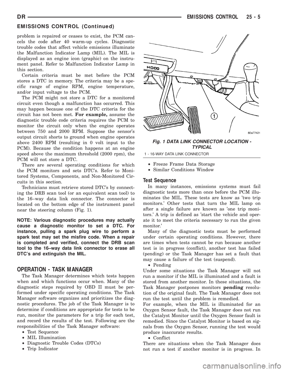
Technicians must retrieve stored DTC's by connect-
ing the DRB scan tool (or an equivalent scan tool) to
the 16±way data link connector. The connector is
located on the bottom edge of the instrument panel
near the steering column (Fig. 1).
NOTE: Various diagnostic procedures may actually
cause a diagnostic monitor to set a DTC. For
instance, pulling a spark plug wire to perform a
spark test may set the misfire code. When a repair
is completed and verified, connect the DRB scan
tool to the 16±way data link connector to erase all
DTC's and extinguish the MIL.
OPERATION - TASK MANAGER
The Task Manager determines which tests happen
when and which functions occur when. Many of the
diagnostic steps required by OBD II must be per-
formed under specific operating conditions. The Task
Manager software organizes and prioritizes the diag-
nostic procedures. The job of the Task Manager is to
determine if conditions are appropriate for tests to be
run, monitor the parameters for a trip for each test,
and record the results of the test. Following are the
responsibilities of the Task Manager software:
²Test Sequence
²MIL Illumination
²Diagnostic Trouble Codes (DTCs)
²Trip Indicator²Freeze Frame Data Storage
²Similar Conditions Window
Test Sequence
In many instances, emissions systems must fail
diagnostic tests more than once before the PCM illu-
minates the MIL. These tests are know as 'two trip
monitors.' Other tests that turn the MIL lamp on
after a single failure are known as 'one trip moni-
tors.' A trip is defined as 'start the vehicle and oper-
ate it to meet the criteria necessary to run the given
monitor.'
Many of the diagnostic tests must be performed
under certain operating conditions. However, there
are times when tests cannot be run because another
test is in progress (conflict), another test has failed
(pending) or the Task Manager has set a fault that
may cause a failure of the test (suspend).
²Pending
Under some situations the Task Manager will not
run a monitor if the MIL is illuminated and a fault is
stored from another monitor. In these situations, the
Task Manager postpones monitorspendingresolu-
tion of the original fault. The Task Manager does not
run the test until the problem is remedied.
For example, when the MIL is illuminated for an
Oxygen Sensor fault, the Task Manager does not run
the Catalyst Monitor until the Oxygen Sensor fault is
remedied. Since the Catalyst Monitor is based on sig-
nals from the Oxygen Sensor, running the test would
produce inaccurate results.
²Conflict
There are situations when the Task Manager does
not run a test if another monitor is in progress. In
Fig. 1 DATA LINK CONNECTOR LOCATION -
TYPICAL
1 - 16-WAY DATA LINK CONNECTOR
DREMISSIONS CONTROL 25 - 5
EMISSIONS CONTROL (Continued)
Page 2857 of 2895
AIRBAG CONTROL MODULE -
INSTALLATION......................8O-12
AIRBAG CONTROL MODULE -
OPERATION.........................8O-10
AIRBAG CONTROL MODULE -
OPERATION, SIDE IMPACT.............8O-54
AIRBAG CONTROL MODULE - REMOVAL . . 8O-11
AIRBAG INDICATOR - DESCRIPTION......8J-18
AIRBAG INDICATOR - OPERATION.......8J-18
AIRBAG ON/OFF SWITCH -
DESCRIPTION, PASSENGER............8O-38
AIRBAG ON/OFF SWITCH -
INSTALLATION, PASSENGER...........8O-39
AIRBAG ON/OFF SWITCH - OPERATION,
PASSENGER........................8O-38
AIRBAG ON/OFF SWITCH - REMOVAL,
PASSENGER........................8O-39
AJAR INDICATOR - DESCRIPTION, DOOR . . 8J-23
AJAR INDICATOR - OPERATION, DOOR . . . 8J-23
AJAR SWITCH - DESCRIPTION, DOOR....8L-25
AJAR SWITCH - OPERATION, DOOR......8L-25
ALIGNMENT - DESCRIPTION, WHEEL.......2-1
ALIGNMENT - OPERATION, WHEEL........2-2
ALIGNMENT - SPECIAL TOOLS,
HEADLAMP..........................8L-7
ALIGNMENT LINK/COIL SUSPENSION -
STANDARD PROCEDURE.................2-5
ALIGNMENT, SPECIAL TOOLS - WHEEL.....2-7
ALIGNMENT, SPECIFICATIONS............2-6
ALUMINUM THREAD REPAIR -
STANDARD PROCEDURE . . 21-156,21-337,21-495
AMBIENT TEMP SENSOR - DESCRIPTION . 8M-10
AMBIENT TEMP SENSOR - OPERATION . . 8M-10
AMBIENT TEMPERATURE SENSOR -
DIAGNOSIS AND TESTING.............8M-11
AMBIENT TEMPERATURE SENSOR
CIRCUIT - DIAGNOSIS AND TESTING....8M-11
AMPLIFIER - DESCRIPTION.............8A-3
AMPLIFIER - INSTALLATION.............8A-4
AMPLIFIER - OPERATION...............8A-3
AMPLIFIER - REMOVAL................8A-3
ANCHOR - DESCRIPTION, CHILD
RESTRAINT.........................8O-14
ANCHOR - INSTALLATION, CHILD
RESTRAINT.........................8O-17
ANCHOR - OPERATION, CHILD
RESTRAINT.........................8O-16
ANCHOR - REMOVAL, CHILD RESTRAINT . 8O-16
ANCHOR & RIGHT OUTBOARD -
INSTALLATION, CENTER...............8O-45
ANCHOR & RIGHT OUTBOARD -
REMOVAL, CENTER...................8O-43
ANTENNA BODY & CABLE -
DESCRIPTION........................8A-4
ANTENNA BODY & CABLE -
INSTALLATION.......................8A-6
ANTENNA BODY & CABLE - OPERATION . . . 8A-4
ANTENNA BODY & CABLE - REMOVAL.....8A-6
ANTENNA BODY AND CABLE -
DIAGNOSIS AND TESTING..............8A-4
ANTENNA CABLE - INSTALLATION,
INSTRUMENT PANEL..................8A-7
ANTENNA CABLE - REMOVAL,
INSTRUMENT PANEL..................8A-6
ANTILOCK - DIAGNOSIS AND TESTING,
REAR WHEEL........................5-42
ANTILOCK BRAKE - DESCRIPTION,
CONTROLLER........................8E-3
ANTILOCK BRAKE - INSTALLATION,
CONTROLLER........................8E-3
ANTILOCK BRAKE - OPERATION,
CONTROLLER........................8E-3
ANTILOCK BRAKE - REMOVAL,
CONTROLLER........................8E-3
A-PILLAR TRIM/GRAB HANDLE -
INSTALLATION.......................23-64
A-PILLAR TRIM/GRAB HANDLE -
REMOVAL..........................23-64
A-PILLAR WEATHERSTRIP RETAINER -
INSTALLATION
.......................23-91
A-PILLAR WEATHERSTRIP RETAINER -
REMOVAL
..........................23-91
APPLICATION TABLE, SPECIFICATIONS -
A/C
................................24-7
AREA LEAKS - DIAGNOSIS AND
TESTING, REAR SEAL
........9-135,9-204,9-64
ARM / ADJUSTER ASSEMBLY -
DESCRIPTION, ROCKER
...............9-124ARM / ADJUSTER ASSEMBLY -
INSTALLATION, ROCKER..........9-124,9-249
ARM / ADJUSTER ASSEMBLY -
REMOVAL, ROCKER.............9-124,9-249
ARM / ADJUSTER ASSY - CLEANING,
ROCKER............................9-310
ARM / ADJUSTER ASSY - DESCRIPTION,
ROCKER............................9-310
ARM / ADJUSTER ASSY - INSPECTION,
ROCKER............................9-311
ARM / ADJUSTER ASSY -
INSTALLATION, ROCKER.....9-198,9-312,9-379
ARM / ADJUSTER ASSY - REMOVAL,
ROCKER.................9-198,9-310,9-379
ARM - DESCRIPTION, ROCKER......9-30,9-36
ARM - DESCRIPTION, WIPER...........8R-18
ARM - INSTALLATION, LOWER
SUSPENSION.........................2-35
ARM - INSTALLATION, PITMAN.........19-36
ARM - INSTALLATION, ROCKER..........9-30
ARM - INSTALLATION, UPPER CONTROL . . . 2-27
ARM - INSTALLATION, WIPER..........8R-19
ARM - OPERATION, WIPER............8R-18
ARM - REMOVAL, LOWER SUSPENSION . . . 2-35
ARM - REMOVAL, PITMAN.............19-35
ARM - REMOVAL, ROCKER..........9-30,9-36
ARM - REMOVAL, UPPER CONTROL......2-27
ARM - REMOVAL, WIPER..............8R-18
ARM BUSHINGS - 2WD (LD) -
INSTALLATION, LOWER CONTROL..........2-14
ARM BUSHINGS - 2WD (LD) -
REMOVAL, LOWER CONTROL............2-12
ARM BUSHINGS - 4WD (LD) -
INSTALLATION, LOWER CONTROL........2-13
ARM BUSHINGS - 4WD (LD) -
REMOVAL, LOWER CONTROL............2-12
ARMREST / SEAT BACK - INSTALLATION,
CENTER............................23-78
ARMREST / SEAT BACK - REMOVAL,
CENTER............................23-77
ASD AND FUEL PUMP RELAYS -
DIAGNOSIS AND TESTING...............8I-7
ASD SENSE - PCM INPUT - OPERATION....8I-6
ASH RECEIVER - INSTALLATION.........23-52
ASH RECEIVER - REMOVAL............23-51
AUDIO - DESCRIPTION.................8A-1
AUDIO - DIAGNOSIS AND TESTING.......8A-2
AUDIO - OPERATION...................8A-1
AUTOMATIC DAY / NIGHT MIRROR -
DESCRIPTION.......................8N-12
AUTOMATIC DAY / NIGHT MIRROR -
DIAGNOSIS AND TESTING.............8N-12
AUTOMATIC DAY / NIGHT MIRROR -
OPERATION.........................8N-12
AUTOMATIC DAY / NIGHT MIRROR -
REMOVAL..........................8N-13
AUTOMATIC LOCKING RETRACTOR -
DESCRIPTION.......................8O-13
AUTOMATIC LOCKING RETRACTOR -
OPERATION.........................8O-14
AUTOMATIC TRANSMISSION -
45RFE/545RFE - DESCRIPTION.........21-489
AUTOMATIC TRANSMISSION -
45RFE/545RFE - OPERATION...........21-490
AUTOMATIC TRANSMISSION - 46RE -
DESCRIPTION......................21-131
AUTOMATIC TRANSMISSION - 46RE -
OPERATION........................21-133
AUTOMATIC TRANSMISSION - 48RE -
DESCRIPTION......................21-312
AUTOMATIC TRANSMISSION - 48RE -
OPERATION........................21-314
AUTOMATIC TRANSMISSION -
DIAGNOSIS AND TESTING......21-139,21-320,
21-491
AUTOMATIC TRANSMISSION FLUID -
DESCRIPTION.........................0-4
AUTOMATIC TRANSMISSION FLUID -
OPERATION...........................0-5
AUXILIARY SPRING BUMPERS (3500) -
INSTALLATION
........................2-40
AUXILIARY SPRING BUMPERS (3500) -
REMOVAL
...........................2-40
AXLE - 10 1/2 AA - ADJUSTMENTS,
REAR
..............................3-104
AXLE - 10 1/2 AA - DESCRIPTION, REAR
. . 3-100
AXLE - 10 1/2 AA - DIAGNOSIS AND
TESTING, REAR
......................3-100AXLE - 10 1/2 AA - INSTALLATION,
REAR..............................3-103
AXLE - 10 1/2 AA - OPERATION, REAR . . . 3-100
AXLE - 10 1/2 AA - REMOVAL, REAR.....3-103
AXLE - 10 1/2 AA - SPECIAL TOOLS,
REAR..............................3-108
AXLE - 10 1/2 AA - SPECIFICATIONS,
REAR..............................3-108
AXLE - 11 1/2 AA - ADJUSTMENTS,
REAR..............................3-131
AXLE - 11 1/2 AA - DESCRIPTION, REAR . . 3-127
AXLE - 11 1/2 AA - DIAGNOSIS AND
TESTING, REAR......................3-127
AXLE - 11 1/2 AA - INSTALLATION,
REAR..............................3-130
AXLE - 11 1/2 AA - OPERATION, REAR . . . 3-127
AXLE - 11 1/2 AA - REMOVAL, REAR.....3-130
AXLE - 11 1/2 AA - SPECIAL TOOLS,
REAR..............................3-135
AXLE - 11 1/2 AA - SPECIFICATIONS,
REAR..............................3-135
AXLE - 9 1/4 - ADJUSTMENTS, REAR.....3-74
AXLE - 9 1/4 - DESCRIPTION, REAR......3-69
AXLE - 9 1/4 - DIAGNOSIS AND
TESTING, REAR.......................3-69
AXLE - 9 1/4 - INSTALLATION, REAR......3-74
AXLE - 9 1/4 - OPERATION, REAR........3-69
AXLE - 9 1/4 - REMOVAL, REAR..........3-74
AXLE - 9 1/4 - SPECIAL TOOLS, REAR.....3-80
AXLE - 9 1/4 - SPECIFICATIONS, REAR......3-79
AXLE - 9 1/4 AA - ADJUSTMENTS,
FRONT..............................3-49
AXLE - 9 1/4 AA - DESCRIPTION, FRONT . . . 3-45
AXLE - 9 1/4 AA - DIAGNOSIS AND
TESTING, FRONT......................3-45
AXLE - 9 1/4 AA - INSTALLATION,
FRONT..............................3-48
AXLE - 9 1/4 AA - OPERATION, FRONT....3-45
AXLE - 9 1/4 AA - REMOVAL, FRONT......3-48
AXLE - 9 1/4 AA - SPECIAL TOOLS,
FRONT..............................3-53
AXLE - 9 1/4 AA - SPECIFICATIONS,
FRONT..............................3-53
AXLE - C205F - ADJUSTMENTS, FRONT....3-21
AXLE - C205F - DESCRIPTION, FRONT.....3-18
AXLE - C205F - DIAGNOSIS AND
TESTING, FRONT......................3-18
AXLE - C205F - INSTALLATION, FRONT....3-21
AXLE - C205F - OPERATION, FRONT......3-18
AXLE - C205F - REMOVAL, FRONT........3-21
AXLE - C205F - SPECIAL TOOLS, FRONT . . . 3-30
AXLE - C205F - SPECIFICATIONS, FRONT . . . 3-29
AXLE - DESCRIPTION...................0-4
AXLE BEARINGS - INSTALLATION . . 3-112,3-139,
3-34,3-84
AXLE BEARINGS - REMOVAL . . 3-112,3-138,3-33,
3-84
AXLE SHAFT SEALS - INSTALLATION . 3-33,3-58,
3-84
AXLE SHAFT SEALS - REMOVAL . 3-33,3-58,3-84
AXLE SHAFTS - ASSEMBLY.............3-58
AXLE SHAFTS - DISASSEMBLY...........3-56
AXLE SHAFTS - INSTALLATION....3-111,3-138,
3-33,3-58,3-83
AXLE SHAFTS - REMOVAL
....3-111,3-138,3-33,
3-56,3-83
BACK - INSTALLATION, CENTER
ARMREST / SEAT
....................23-78
BACK - REAR - INSTALLATION, SEAT
.....23-84
BACK - REAR - REMOVAL, SEAT
........23-84
BACK - REMOVAL, CENTER ARMREST /
SEAT
..............................23-77
BACK CUSHION / COVER - FRONT -
INSTALLATION, SEAT
.................23-83
BACK CUSHION / COVER - FRONT -
REMOVAL, SEAT
.....................23-83
BACK CUSHION / COVER - REAR -
INSTALLATION, SEAT
.................23-85
BACK CUSHION / COVER - REAR -
REMOVAL, SEAT
.....................23-85
BACK HINGE - INSTALLATION, CENTER
SEAT
..............................23-80
BACK HINGE - REMOVAL, CENTER SEAT
. . 23-79
BACK INERTIA HINGE COVER -
INSTALLATION, CENTER SEAT
..........23-78
BACK INERTIA HINGE COVER -
REMOVAL, CENTER SEAT
..............23-78
2 INDEXDR
Description Group-Page Description Group-Page Description Group-Page
Page 2858 of 2895
BACK LID - INSTALLATION, CENTER
SEAT ..............................23-80
BACK LID - REMOVAL, CENTER SEAT....23-80
BACK PANEL TRIM - INSTALLATION,
REAR CAB..........................23-70
BACK PANEL TRIM - REMOVAL, REAR
CAB ...............................23-70
BACK REAR - FOOTMANS LOOP
BRACKETS - INSTALLATION, SEAT.......23-85
BACK REAR - FOOTMANS LOOP
BRACKETS - REMOVAL, SEAT...........23-85
BACKLITE - INSTALLATION.............23-86
BACKLITE - REMOVAL.................23-86
BACKLITE VENT GLASS - INSTALLATION . . 23-87
BACKLITE VENT GLASS - REMOVAL......23-87
BACKUP LAMP - INSTALLATION..........8L-7
BACKUP LAMP - REMOVAL.............8L-7
BACKUP LAMP SWITCH - DESCRIPTION . . . 8L-7
BACKUP LAMP SWITCH - DIAGNOSIS
AND TESTING........................8L-8
BACKUP LAMP SWITCH - OPERATION.....8L-8
BALANCE - STANDARD PROCEDURE,
TIRE AND WHEEL.....................22-4
BALANCE SHAFT - INSTALLATION........9-79
BALANCE SHAFT - REMOVAL............9-79
BALL JOINT - DIAGNOSIS AND TESTING,
LOWER.............................2-18
BALL JOINT - DIAGNOSIS AND TESTING,
UPPER..............................2-26
BALL JOINT - INSTALLATION, LOWER . . 2-19,2-33
BALL JOINT - INSTALLATION, UPPER.....2-33
BALL JOINT - REMOVAL, LOWER.....2-18,2-32
BALL JOINT - REMOVAL, UPPER.........2-33
BAND OPERATION - DIAGNOSIS AND
TESTING, AIR TESTING
TRANSMISSION CLUTCH.......21-143,21-324
BANDS - ADJUSTMENT.........21-193,21-374
BANDS - DESCRIPTION.........21-193,21-373
BANDS - OPERATION..........21-193,21-374
BAR - DESCRIPTION, STABILIZER........2-24
BAR - DESCRIPTION, TORSION..........2-25
BAR - INSTALLATION, STABILIZER....2-24,2-37
BAR - INSTALLATION, TORSION..........2-26
BAR - INSTALLATION, TRACK...........19-37
BAR - OPERATION, STABILIZER..........2-24
BAR - OPERATION, TORSION............2-25
BAR - REMOVAL, STABILIZER.......2-24,2-37
BAR - REMOVAL, TORSION.............2-25
BAR - REMOVAL, TRACK..............19-37
BAR CROSS MEMBER BUSHING -
INSTALLATION, TORSION...............2-14
BAR CROSSMEMBER BUSHING -
REMOVAL, TORSION...................2-12
BASE BRAKE, SPECIFICATIONS............5-7
BASE BRAKE SYSTEM - DIAGNOSIS AND
TESTING.............................5-2
BASE BRAKES, SPECIAL TOOLS...........5-5
BASECOAT/CLEARCOAT FINISH -
DESCRIPTION.......................23-74
BATTERIES - STANDARD PROCEDURE,
RKE TRANSMITTER...................8N-9
BATTERY - DESCRIPTION...............8F-7
BATTERY - DIAGNOSIS AND TESTING.....8F-7
BATTERY CABLES - DESCRIPTION.......8F-14
BATTERY CABLES - DIAGNOSIS AND
TESTING...........................8F-15
BATTERY CABLES - INSTALLATION.......8F-17
BATTERY CABLES - OPERATION.........8F-14
BATTERY CABLES - REMOVAL..........8F-16
BATTERY CHARGING - STANDARD
PROCEDURE.........................8F-8
BATTERY HOLDDOWN - DESCRIPTION....8F-14
BATTERY HOLDDOWN - INSTALLATION . . . 8F-14
BATTERY HOLDDOWN - OPERATION.....8F-14
BATTERY HOLDDOWN - REMOVAL.......8F-14
BATTERY SYSTEM - CLEANING...........8F-4
BATTERY SYSTEM - DESCRIPTION........8F-1
BATTERY SYSTEM - DIAGNOSIS AND
TESTING............................8F-2
BATTERY SYSTEM - INSPECTION.........8F-6
BATTERY SYSTEM - OPERATION
.........8F-2
BATTERY SYSTEM - SPECIFICATIONS
......8F-6
BATTERY SYSTEM SPECIAL TOOLS,
SPECIAL TOOLS
......................8F-7
BATTERY TEMPERATURE SENSOR -
DESCRIPTION
.......................8F-21
BATTERY TEMPERATURE SENSOR -
INSTALLATION
.......................8F-21BATTERY TEMPERATURE SENSOR -
OPERATION.........................8F-21
BATTERY TEMPERATURE SENSOR -
REMOVAL..........................8F-21
BATTERY TESTER - STANDARD
PROCEDURE, USING MICRO 420........8F-12
BATTERY TRAY - DESCRIPTION.........8F-17
BATTERY TRAY - INSTALLATION.........8F-18
BATTERY TRAY - OPERATION...........8F-17
BATTERY TRAY - REMOVAL............8F-17
BEAM INDICATOR - DESCRIPTION, HIGH . . 8J-27
BEAM INDICATOR - OPERATION, HIGH....8J-28
BEARING - ADJUSTMENTS, CENTER.......3-8
BEARING - FITTING - STANDARD
PROCEDURE, CRANKSHAFT MAIN . . 9-133,9-202
BEARING - INSTALLATION, CENTER........3-8
BEARING - INSTALLATION, CLUTCH
RELEASE............................6-11
BEARING - INSTALLATION, HUB..........2-31
BEARING - INSTALLATION, OUTPUT
SHAFT FRONT................21-217,21-395
BEARING - INSTALLATION, OUTPUT
SHAFT REAR.................21-217,21-396
BEARING - INSTALLATION, PILOT........6-12
BEARING - REMOVAL, CENTER...........3-8
BEARING - REMOVAL, CLUTCH RELEASE . . . 6-11
BEARING - REMOVAL, HUB.............2-30
BEARING - REMOVAL, OUTPUT SHAFT
FRONT......................21-217,21-395
BEARING - REMOVAL, OUTPUT SHAFT
REAR.......................21-217,21-395
BEARING - REMOVAL, PILOT............6-12
BEARING AND CRANKSHAFT JOURNAL
CLEARANCE - STANDARD
PROCEDURE, CONNECTING ROD........9-321
BEARING CLEARANCE - STANDARD
PROCEDURE, MAIN...................9-322
BEARING FITTING - STANDARD
PROCEDURE, CONNECTING ROD . . . 9-128,9-251,
9-382
BEARING FITTING - STANDARD
PROCEDURE, CRANKSHAFT MAIN.......9-253
BEARING FITTING, STANDARD
PROCEDURE - CONNECTING ROD........9-48
BEARING FITTING, STANDARD
PROCEDURE - MAIN...................9-43
BEARINGS - DESCRIPTION,
CRANKSHAFT MAIN..................9-253
BEARINGS - INSPECTION, CRANKSHAFT
MAIN.........................9-133,9-203
BEARINGS - INSTALLATION, AXLE . . 3-112,3-139,
3-34,3-84
BEARINGS - INSTALLATION, CAMSHAFT . . 9-320,
9-381
BEARINGS - INSTALLATION,
CRANKSHAFT MAIN.............9-254,9-383
BEARINGS - INSTALLATION,
DIFFERENTIAL CASE . 3-121,3-148,3-39,3-65,3-94
BEARINGS - OPERATION, CRANKSHAFT
MAIN..............................9-253
BEARINGS - REMOVAL, AXLE . 3-112,3-138,3-33,
3-84
BEARINGS - REMOVAL, CAMSHAFT . 9-317,9-380
BEARINGS - REMOVAL, CRANKSHAFT
MAIN.........................9-254,9-383
BEARINGS - REMOVAL, DIFFERENTIAL
CASE.............3-121,3-148,3-39,3-64,3-93
BEARINGS - STANDARD PROCEDURE,
FITTING CRANKSHAFT MAIN...........9-383
BELT / CHAIN COVER(S) -
INSTALLATION, TIMING . 9-169,9-278,9-404,9-81
BELT / CHAIN COVER(S) - REMOVAL,
TIMING..............9-168,9-278,9-404,9-80
BELT - DIAGNOSIS AND TESTING,
ACCESSORY DRIVE............7-25,7-28,7-31
BELT - INSTALLATION, FRONT CENTER
SEAT ..............................8O-27
BELT - REMOVAL, FRONT CENTER SEAT . . 8O-26
BELT & RETRACTOR - INSTALLATION,
FRONT CENTER SEAT
.................8O-26
BELT & RETRACTOR - INSTALLATION,
REAR CENTER SEAT
..................8O-40
BELT & RETRACTOR - INSTALLATION,
REAR OUTBOARD SEAT
...............8O-42
BELT & RETRACTOR - REMOVAL, FRONT
CENTER SEAT
.......................8O-25
BELT & RETRACTOR - REMOVAL, REAR
CENTER SEAT
.......................8O-39BELT & RETRACTOR - REMOVAL, REAR
OUTBOARD SEAT....................8O-41
BELT BUCKLE - INSTALLATION, FRONT
OUTBOARD SEAT....................8O-34
BELT BUCKLE - REMOVAL, FRONT
OUTBOARD SEAT....................8O-33
BELT MOLDING - INSTALLATION, FRONT
DOOR INNER........................23-93
BELT MOLDING - INSTALLATION, FRONT
DOOR OUTER.......................23-93
BELT MOLDING - INSTALLATION, REAR
DOOR INNER........................23-94
BELT MOLDING - INSTALLATION, REAR
DOOR OUTER.......................23-94
BELT MOLDING - REMOVAL, FRONT
DOOR INNER........................23-93
BELT MOLDING - REMOVAL, FRONT
DOOR OUTER.......................23-93
BELT MOLDING - REMOVAL, REAR
DOOR INNER........................23-94
BELT MOLDING - REMOVAL, REAR
DOOR OUTER.......................23-94
BELT SWITCH - DESCRIPTION, SEAT.....8O-46
BELT SWITCH - DIAGNOSIS AND
TESTING, SEAT......................8O-47
BELT SWITCH - OPERATION, SEAT.......8O-46
BELT TENSION REDUCER -
DESCRIPTION, SEAT..................8O-48
BELT TENSION REDUCER - DIAGNOSIS
AND TESTING, SEAT..................8O-49
BELT TENSION REDUCER - OPERATION,
SEAT ..............................8O-49
BELT TENSIONER - DESCRIPTION, SEAT....8O-47
BELT TENSIONER - OPERATION, SEAT....8O-48
BELT TENSIONERS - 3.7L / 4.7L -
DESCRIPTION........................7-22
BELT TENSIONERS - 3.7L / 4.7L -
INSTALLATION........................7-23
BELT TENSIONERS - 3.7L / 4.7L -
OPERATION..........................7-22
BELT TENSIONERS - 3.7L / 4.7L -
REMOVAL...........................7-22
BELT TENSIONERS - 5.9L -
DESCRIPTION........................7-23
BELT TENSIONERS - 5.9L -
INSTALLATION........................7-24
BELT TENSIONERS - 5.9L - OPERATION....7-23
BELT TENSIONERS - 5.9L - REMOVAL.....7-23
BELT TENSIONERS - 5.9L DIESEL -
DESCRIPTION........................7-24
BELT TENSIONERS - 5.9L DIESEL -
INSTALLATION........................7-25
BELT TENSIONERS - 5.9L DIESEL -
OPERATION..........................7-24
BELT TENSIONERS - 5.9L DIESEL -
REMOVAL...........................7-25
BELT TURNING LOOP ADJUSTER -
INSTALLATION, SEAT.................8O-50
BELT TURNING LOOP ADJUSTER -
REMOVAL, SEAT.....................8O-50
BELT/CHAIN AND SPROCKETS -
INSPECTION, TIMING.............9-171,9-83
BELT/CHAIN AND SPROCKETS -
INSTALLATION, TIMING . 9-172,9-279,9-406,9-84
BELT/CHAIN AND SPROCKETS -
REMOVAL, TIMING.....9-169,9-279,9-405,9-81
BELTS - 3.7L / 4.7L - INSTALLATION,
DRIVE..............................7-27
BELTS - 3.7L / 4.7L - REMOVAL, DRIVE....7-27
BELTS - 5.9L - INSTALLATION, DRIVE.....7-31
BELTS - 5.9L - REMOVAL, DRIVE.........7-30
BELTS - 5.9L DIESEL - INSTALLATION,
DRIVE..............................7-34
BELTS - 5.9L DIESEL - REMOVAL, DRIVE . . 7-34
BEZEL - INSTALLATION, CLUSTER.......23-50
BEZEL - INSTALLATION, INSTRUMENT
PANEL CENTER......................23-58
BEZEL - INSTALLATION, INSTRUMENT
PANEL DRIVER SIDE..................23-59
BEZEL - INSTALLATION, INSTRUMENT
PANEL HEADLAMP SWITCH
............23-57
BEZEL - REMOVAL, CLUSTER
...........23-50
BEZEL - REMOVAL, INSTRUMENT PANEL
CENTER
............................23-58
BEZEL - REMOVAL, INSTRUMENT PANEL
DRIVER SIDE
........................23-58
BEZEL - REMOVAL, INSTRUMENT PANEL
HEADLAMP SWITCH
..................23-57
DRINDEX 3
Description Group-Page Description Group-Page Description Group-Page