2003 DODGE RAM tire pressure
[x] Cancel search: tire pressurePage 230 of 2895

and cups will also have to be replaced after flush-
ing. Use clean brake fluid to flush the system.
(4) Check parking brake operation. Verify free
movement and full release of cables and pedal. Also
note if vehicle was being operated with parking
brake partially applied.
(5) Check brake pedal operation. Verify that pedal
does not bind and has adequate free play. If pedal
lacks free play, check pedal and power booster for
being loose or for bind condition. Do not road test
until condition is corrected.
(6) Check booster vacuum check valve and hose.
(7) If components checked appear OK, road test
the vehicle.
ROAD TESTING
(1) If complaint involved low brake pedal, pump
pedal and note if it comes back up to normal height.
(2) Check brake pedal response with transmission
in Neutral and engine running. Pedal should remain
firm under constant foot pressure.
(3) During road test, make normal and firm brake
stops in 25-40 mph range. Note faulty brake opera-
tion such as low pedal, hard pedal, fade, pedal pulsa-
tion, pull, grab, drag, noise, etc.
(4) Attempt to stop the vehicle with the parking
brake only and note grab, drag, noise, etc.
PEDAL FALLS AWAY
A brake pedal that falls away under steady foot
pressure is generally the result of a system leak. The
leak point could be at a brake line, fitting, hose, or
caliper/wheel cylinder. If leakage is severe, fluid will
be evident at or around the leaking component.
Internal leakage (seal by-pass) in the master cylin-
der caused by worn or damaged piston cups, may
also be the problem cause.
An internal leak in the ABS or RWAL system may
also be the problem with no physical evidence.
LOW PEDAL
If a low pedal is experienced, pump the pedal sev-
eral times. If the pedal comes back up worn linings,
rotors, drums, or rear brakes out of adjustment are
the most likely causes. The proper course of action is
to inspect and replace all worn component and make
the proper adjustments.
SPONGY PEDAL
A spongy pedal is most often caused by air in the
system. However, thin brake drums or substandard
brake lines and hoses can also cause a spongy pedal.
The proper course of action is to bleed the system,
and replace thin drums and substandard quality
brake hoses if suspected.HARD PEDAL OR HIGH PEDAL EFFORT
A hard pedal or high pedal effort may be due to
lining that is water soaked, contaminated, glazed, or
badly worn. The power booster or check valve could
also be faulty.
PEDAL PULSATION
Pedal pulsation is caused by components that are
loose, or beyond tolerance limits.
The primary cause of pulsation are disc brake
rotors with excessive lateral runout or thickness vari-
ation, or out of round brake drums. Other causes are
loose wheel bearings or calipers and worn, damaged
tires.
NOTE: Some pedal pulsation may be felt during
ABS activation.
BRAKE DRAG
Brake drag occurs when the lining is in constant
contact with the rotor or drum. Drag can occur at one
wheel, all wheels, fronts only, or rears only.
Drag is a product of incomplete brake shoe release.
Drag can be minor or severe enough to overheat the
linings, rotors and drums.
Minor drag will usually cause slight surface char-
ring of the lining. It can also generate hard spots in
rotors and drums from the overheat-cool down pro-
cess. In most cases, the rotors, drums, wheels and
tires are quite warm to the touch after the vehicle is
stopped.
Severe drag can char the brake lining all the way
through. It can also distort and score rotors and
drums to the point of replacement. The wheels, tires
and brake components will be extremely hot. In
severe cases, the lining may generate smoke as it
chars from overheating.
Common causes of brake drag are:
²Seized or improperly adjusted parking brake
cables.
²Loose/worn wheel bearing.
²Seized caliper or wheel cylinder piston.
²Caliper binding on corroded bushings or rusted
slide surfaces.
²Loose caliper mounting.
²Drum brake shoes binding on worn/damaged
support plates.
²Mis-assembled components.
²Long booster output rod.
If brake drag occurs at all wheels, the problem
may be related to a blocked master cylinder return
port, or faulty power booster (binds-does not release).
BRAKE FADE
Brake fade is usually a product of overheating
caused by brake drag. However, brake overheating
DRBRAKES - BASE 5 - 3
BRAKES - BASE (Continued)
Page 236 of 2895

(5) Remove the banjo bolt at the caliper (Fig. 7).
(6) Remove the hose.
REMOVAL - FRONT HOSE
(1) Install a prop rod on the brake pedal to keep
pressure on the brake system.
(2) Raise and support vehicle.
(3) Remove the tire and wheel assembly.
(4) Remove the brake hose from the brake line
located at the frame (Fig. 8).
(5) Remove the brake hose banjo bolt at the caliper
(Fig. 8).
(6) Remove the mounting bolt securing the brake
hose to the frame and remove the wheel speed sensor
wire from the brake hose (Fig. 8).
(7) Remove the hose.
INSTALLATION
INSTALLATION - REAR BRAKE HOSE
(1) Install the hose.
(2) Install the mounting bolt for the brake hose at
the axle (Fig. 6).
(3) Install the two brake lines at the bottom of the
hose located at the axle (Fig. 6).
(4) Install the vent tube (Fig. 6).
(5) Install the brake hose clip at the top of the
hose located at the frame (Fig. 5).
(6) Install the brake line to the hose at the frame
(Fig. 5).
(7) Lower the vehicle and remove the support.
(8) Remove the prop rod.
(9) Bleed the brake system (Refer to 5 - BRAKES -
STANDARD PROCEDURE).
INSTALLATION - REAR TUBE / HOSE
ASSEMBLY
(1) Install the hose.
(2) Install the banjo bolt at the caliper (Fig. 7).
(3) Install the mounting bolt for the brake hose at
the axle (Fig. 7).
(4) Install the brake line located at the axle.
(5) Lower the vehicle and remove the support.
(6) Remove the prop rod.
(7) Bleed the brake system (Refer to 5 - BRAKES -
STANDARD PROCEDURE).
INSTALLATION - FRONT BRAKE HOSE
(1) Install the hose.
(2) Install the mounting bolt for the brake hose at
the frame (Fig. 9).
Fig. 6 REAR HOSE
1 - BRAKE HOSE
2 - VENT HOSE
3 - BRAKE LINES
Fig. 7 BRAKE LINE WITH RUBBER HOSE
1 - BANJO BOLT
2 - MOUNTING BOLT
3 - REAR TUBE / HOSE ASSEMBLY
Fig. 8 BRAKE HOSE MOUNTED PASSENGER SIDE
1 - MOUNTING BOLT
2 - BRAKE HOSE
3 - BANJO BOLT
4 - WHEEL SPEED SENSOR WIRE
DRBRAKES - BASE 5 - 9
BRAKE LINES (Continued)
Page 239 of 2895
OPERATION
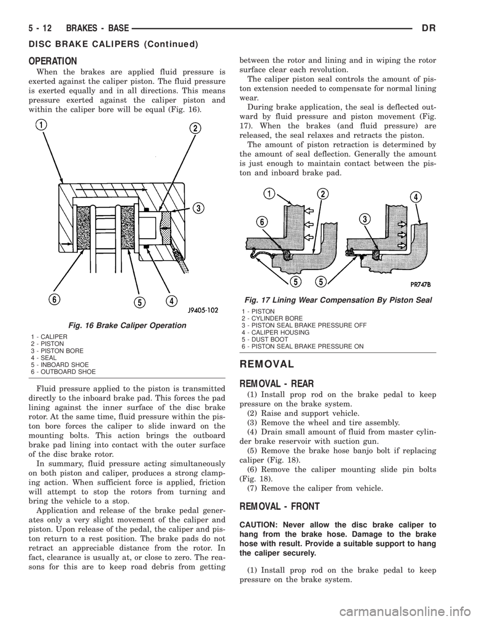
When the brakes are applied fluid pressure is
exerted against the caliper piston. The fluid pressure
is exerted equally and in all directions. This means
pressure exerted against the caliper piston and
within the caliper bore will be equal (Fig. 16).
Fluid pressure applied to the piston is transmitted
directly to the inboard brake pad. This forces the pad
lining against the inner surface of the disc brake
rotor. At the same time, fluid pressure within the pis-
ton bore forces the caliper to slide inward on the
mounting bolts. This action brings the outboard
brake pad lining into contact with the outer surface
of the disc brake rotor.
In summary, fluid pressure acting simultaneously
on both piston and caliper, produces a strong clamp-
ing action. When sufficient force is applied, friction
will attempt to stop the rotors from turning and
bring the vehicle to a stop.
Application and release of the brake pedal gener-
ates only a very slight movement of the caliper and
piston. Upon release of the pedal, the caliper and pis-
ton return to a rest position. The brake pads do not
retract an appreciable distance from the rotor. In
fact, clearance is usually at, or close to zero. The rea-
sons for this are to keep road debris from gettingbetween the rotor and lining and in wiping the rotor
surface clear each revolution.
The caliper piston seal controls the amount of pis-
ton extension needed to compensate for normal lining
wear.
During brake application, the seal is deflected out-
ward by fluid pressure and piston movement (Fig.
17). When the brakes (and fluid pressure) are
released, the seal relaxes and retracts the piston.
The amount of piston retraction is determined by
the amount of seal deflection. Generally the amount
is just enough to maintain contact between the pis-
ton and inboard brake pad.
REMOVAL
REMOVAL - REAR
(1) Install prop rod on the brake pedal to keep
pressure on the brake system.
(2) Raise and support vehicle.
(3) Remove the wheel and tire assembly.
(4) Drain small amount of fluid from master cylin-
der brake reservoir with suction gun.
(5) Remove the brake hose banjo bolt if replacing
caliper (Fig. 18).
(6) Remove the caliper mounting slide pin bolts
(Fig. 18).
(7) Remove the caliper from vehicle.
REMOVAL - FRONT
CAUTION: Never allow the disc brake caliper to
hang from the brake hose. Damage to the brake
hose with result. Provide a suitable support to hang
the caliper securely.
(1) Install prop rod on the brake pedal to keep
pressure on the brake system.
Fig. 16 Brake Caliper Operation
1 - CALIPER
2 - PISTON
3 - PISTON BORE
4 - SEAL
5 - INBOARD SHOE
6 - OUTBOARD SHOE
Fig. 17 Lining Wear Compensation By Piston Seal
1 - PISTON
2 - CYLINDER BORE
3 - PISTON SEAL BRAKE PRESSURE OFF
4 - CALIPER HOUSING
5 - DUST BOOT
6 - PISTON SEAL BRAKE PRESSURE ON
5 - 12 BRAKES - BASEDR
DISC BRAKE CALIPERS (Continued)
Page 240 of 2895
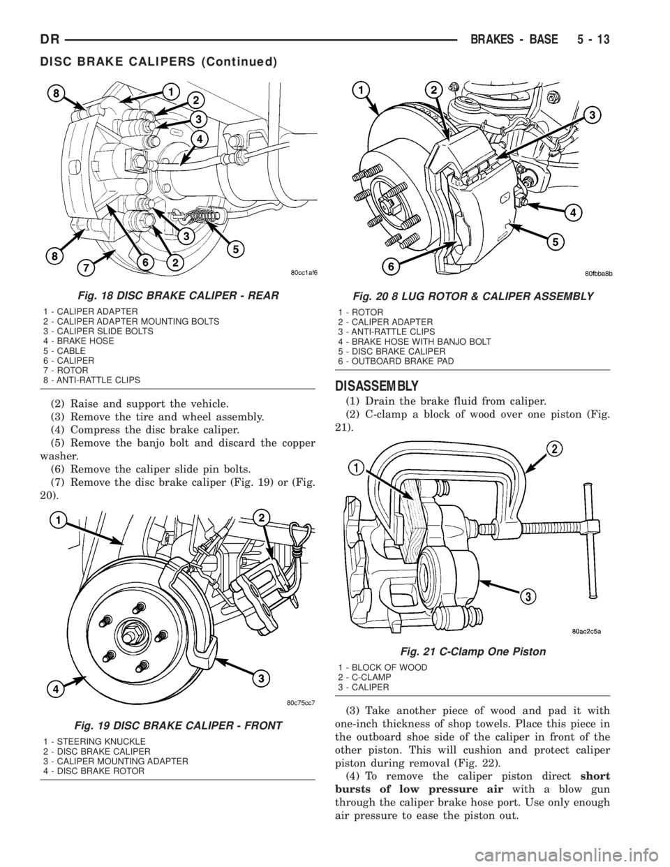
(2) Raise and support the vehicle.
(3) Remove the tire and wheel assembly.
(4) Compress the disc brake caliper.
(5) Remove the banjo bolt and discard the copper
washer.
(6) Remove the caliper slide pin bolts.
(7) Remove the disc brake caliper (Fig. 19) or (Fig.
20).
DISASSEMBLY
(1) Drain the brake fluid from caliper.
(2) C-clamp a block of wood over one piston (Fig.
21).
(3) Take another piece of wood and pad it with
one-inch thickness of shop towels. Place this piece in
the outboard shoe side of the caliper in front of the
other piston. This will cushion and protect caliper
piston during removal (Fig. 22).
(4) To remove the caliper piston directshort
bursts of low pressure airwith a blow gun
through the caliper brake hose port. Use only enough
air pressure to ease the piston out.
Fig. 18 DISC BRAKE CALIPER - REAR
1 - CALIPER ADAPTER
2 - CALIPER ADAPTER MOUNTING BOLTS
3 - CALIPER SLIDE BOLTS
4 - BRAKE HOSE
5 - CABLE
6 - CALIPER
7 - ROTOR
8 - ANTI-RATTLE CLIPS
Fig. 19 DISC BRAKE CALIPER - FRONT
1 - STEERING KNUCKLE
2 - DISC BRAKE CALIPER
3 - CALIPER MOUNTING ADAPTER
4 - DISC BRAKE ROTOR
Fig. 20 8 LUG ROTOR & CALIPER ASSEMBLY
1 - ROTOR
2 - CALIPER ADAPTER
3 - ANTI-RATTLE CLIPS
4 - BRAKE HOSE WITH BANJO BOLT
5 - DISC BRAKE CALIPER
6 - OUTBOARD BRAKE PAD
Fig. 21 C-Clamp One Piston
1 - BLOCK OF WOOD
2 - C-CLAMP
3 - CALIPER
DRBRAKES - BASE 5 - 13
DISC BRAKE CALIPERS (Continued)
Page 255 of 2895

(7) Install the hydraulic booster pressure lines to
the bracket and booster.
(8) Tighten the pressure lines to 41 N´m (30 ft.
lbs.).
NOTE: Inspect o-rings on the pressure line fittings
to insure they are in good condition before installa-
tion. Replace o-rings if necessary.
(9) Install the return hose to the booster.
(10) Bleed base brake system, (Refer to 5 -
BRAKES/HYDRAULIC/MECHANICAL - STAN-
DARD PROCEDURE).
(11) Fill the power steering pump with fluid,
(Refer to 19 - STEERING/PUMP - STANDARD PRO-
CEDURE).
CAUTION: MOPAR (MS-9602) ATF+4 is to be used in
the power steering system. No other power steering
or automatic transmission fluid is to be used in the
system. Damage may result to the power steering
pump and system if any other fluid is used, and do
not overfill.
(12) Bleed the hydraulic booster (Refer to 5 -
BRAKES/HYDRAULIC/MECHANICAL/POWER
BRAKE BOOSTER - STANDARD PROCEDURE).
ROTORS
REMOVAL
REMOVAL - REAR
(1) Raise and support the vehicle
(2) Remove the tire and wheel assembly.
(3) Remove the disc brake caliper, (Refer to 5 -
BRAKES/HYDRAULIC/MECHANICAL/DISC
BRAKE CALIPERS - REMOVAL).
(4) Remove the caliper adapter bolts (Fig.
50).(Refer to 5 - BRAKES/HYDRAULIC/MECHANI-
CAL/DISC BRAKE CALIPER ADAPTER -
REMOVAL)
(5) Remove the retianing clips and rotor assembly
(Fig. 50).
REMOVAL - FRONT
(1) Raise and support the vehicle.
(2) Remove the wheel and tire assembly.
(3) Remove the caliper from the steering knuckle,
(Refer to 5 - BRAKES/HYDRAULIC/MECHANICAL/
DISC BRAKE CALIPERS - REMOVAL) and remove
caliper adapter assembly (Fig. 51).
NOTE: Do not allow brake hose to support caliper
adapter assembly.(4) Remove the rotor from the hub/bearing wheel
studs (Fig. 52) or (Fig. 53).
INSTALLATION
INSTALLATION - REAR
(1) Install the rotor to the axleshaft (Fig. 50).
Fig. 50 REAR ROTOR
1 - ROTOR
2 - CALIPER ADAPTER
3 - CALIPER
Fig. 51 Caliper Adapter Assembly
1 - KNUCKLE
2 - CALIPER
3 - ROTOR
5 - 28 BRAKES - BASEDR
HYDRO-BOOST BRAKE BOOSTER (Continued)
Page 305 of 2895
CAUTION: Follow manufacturers instructions when
using these products.
STANDARD PROCEDUREÐDRAINING COOLING
SYSTEM 3.7L/4.7L/5.7L ENGINE
WARNING: DO NOT REMOVE THE CYLINDER
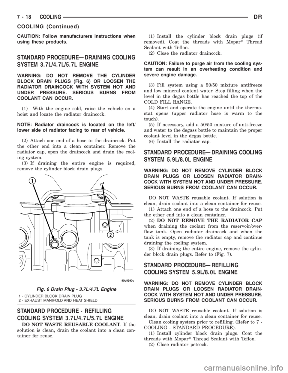
BLOCK DRAIN PLUGS (Fig. 6) OR LOOSEN THE
RADIATOR DRAINCOCK WITH SYSTEM HOT AND
UNDER PRESSURE. SERIOUS BURNS FROM
COOLANT CAN OCCUR.
(1) With the engine cold, raise the vehicle on a
hoist and locate the radiator draincock.
NOTE: Radiator draincock is located on the left/
lower side of radiator facing to rear of vehicle.
(2) Attach one end of a hose to the draincock. Put
the other end into a clean container. Remove the
radiator cap, open the draincock and drain the cool-
ing system.
(3) If draining the entire engine is required,
remove the cylinder block drain plugs.
STANDARD PROCEDURE - REFILLING
COOLING SYSTEM 3.7L/4.7L/5.7L ENGINE
DO NOT WASTE REUSABLE COOLANT.Ifthe
solution is clean, drain the coolant into a clean con-
tainer for reuse.(1) Install the cylinder block drain plugs (if
removed). Coat the threads with MopartThread
Sealant with Teflon.
(2) Close the radiator draincock.
CAUTION: Failure to purge air from the cooling sys-
tem can result in an overheating condition and
severe engine damage.
(3) Fill system using a 50/50 mixture antifreeze
and low mineral content water. Stop filling when the
level in the degas bottle has reached the top of the
COLD FILL RANGE.
(4) Start and operate the engine until the thermo-
stat opens (upper radiator hose is warm to the
touch).
(5) If necessary, add a 50/50 mixture of anti-freeze
and water to the degass bottle to maintain the proper
coolant level in the degas bottle.
(6) Install the radiator cap.
STANDARD PROCEDUREÐDRAINING COOLING
SYSTEM 5.9L/8.0L ENGINE
WARNING: DO NOT REMOVE CYLINDER BLOCK
DRAIN PLUGS OR LOOSEN RADIATOR DRAIN-
COCK WITH SYSTEM HOT AND UNDER PRESSURE.
SERIOUS BURNS FROM COOLANT CAN OCCUR.
DO NOT WASTE reusable coolant. If solution is
clean, drain coolant into a clean container for reuse.
(1) Attach one end of a hose to the draincock. Put
the other end into a clean container.
(2)DO NOT REMOVE THE RADIATOR CAP
when draining the coolant from the reservoir/over-
flow tank. Open radiator draincock and when the
tank is empty, remove the radiator cap and continue
draining the cooling system.
(3) If draining the entire engine, remove the cylin-
der block drain plugs. Refer to (Fig. 7).
STANDARD PROCEDUREÐREFILLING
COOLING SYSTEM 5.9L/8.0L ENGINE
WARNING: DO NOT REMOVE CYLINDER BLOCK
DRAIN PLUGS OR LOOSEN RADIATOR DRAIN-
COCK WITH SYSTEM HOT AND UNDER PRESSURE.
SERIOUS BURNS FROM COOLANT CAN OCCUR.
DO NOT WASTE reusable coolant. If solution is
clean, drain coolant into a clean container for reuse.
Clean cooling system prior to refilling. (Refer to 7 -
COOLING - STANDARD PROCEDURE).
(1) Install cylinder block drain plugs. Coat the
threads with MopartThread Sealant with Teflon.
(2) Close radiator petcock.
Fig. 6 Drain Plug - 3.7L/4.7L Engine
1 - CYLINDER BLOCK DRAIN PLUG
2 - EXHAUST MANIFOLD AND HEAT SHIELD
7 - 18 COOLINGDR
COOLING (Continued)
Page 498 of 2895

the vehicle speed remains greater than about twenty-
four kilometers-per-hour (fifteen miles-per-hour).
²Vacuum Fluorescent Display Synchroniza-
tion- The EMIC transmits electronic panel lamp
dimming level messages which allows all other elec-
tronic modules on the PCI data bus with Vacuum
Fluorescent Display (VFD) units to coordinate their
illumination intensity with that of the EMIC VFD
units.
²Vehicle Theft Security System- The EMIC
monitors inputs from the door cylinder lock switch-
(es), the door ajar switches, the ignition switch, and
the Remote Keyless Entry (RKE) receiver module,
then provides electronic horn and lighting request
messages to the Front Control Module (FCM) located
on the Integrated Power Module (IPM) for the appro-
priate VTSS alarm output features.
²Wiper/Washer System Control- The EMIC
provides electronic wiper and/or washer request mes-
sages to the Front Control Module (FCM) located on
the Integrated Power Module (IPM) for the appropri-
ate wiper and washer system features. (Refer to 8 -
ELECTRICAL/WIPERS/WASHERS - DESCRIP-
TION).
The EMIC houses six analog gauges and has pro-
visions for up to twenty-three indicators (Fig. 3) or
(Fig. 4). The EMIC includes the following analog
gauges:
²Coolant Temperature Gauge
²Fuel Gauge
²Oil Pressure Gauge
²Speedometer
²Tachometer
²Voltage Gauge
Some of the EMIC indicators are automatically
configured when the EMIC is connected to the vehi-
cle electrical system for compatibility with certain
optional equipment or equipment required for regula-
tory purposes in certain markets. While each EMIC
may have provisions for indicators to support every
available option, the configurable indicators will not
be functional in a vehicle that does not have the
equipment that an indicator supports. The EMIC
includes provisions for the following indicators (Fig.
3) or (Fig. 4):
²Airbag Indicator (with Airbag System only)
²Antilock Brake System (ABS) Indicator
(with ABS or Rear Wheel Anti-Lock [RWAL]
brakes only)
²Brake Indicator
²Cargo Lamp Indicator
²Check Gauges Indicator
²Cruise Indicator (with Speed Control only)
²Door Ajar Indicator
²Electronic Throttle Control (ETC) Indicator
(with 5.7L Gasoline Engine only)²Gear Selector Indicator (with Automatic
Transmission only)
²High Beam Indicator
²Lamp Out Indicator
²Low Fuel Indicator
²Malfunction Indicator Lamp (MIL)
²Overdrive-Off Indicator (with Automatic
Transmission only)
²Seatbelt Indicator
²Security Indicator (with Sentry Key Immo-
bilizer & Vehicle Theft Security Systems only)
²Service Four-Wheel Drive Indicator (with
Four-Wheel Drive only)
²Transmission Overtemp Indicator (with
Automatic Transmission only)
²Turn Signal (Right and Left) Indicators
²Upshift Indicator (with Manual Transmis-
sion only)
²Washer Fluid Indicator
²Wait-To-Start Indicator (with Diesel Engine
only)
²Water-In-Fuel Indicator (with Diesel Engine
only)
Each indicator in the EMIC, except those located
within one of the VFD units, is illuminated by a ded-
icated LED that is soldered onto the EMIC electronic
circuit board. The LED units are not available for
service replacement and, if damaged or faulty, the
entire EMIC must be replaced. Cluster illumination
is accomplished by dimmable incandescent back
lighting, which illuminates the gauges for visibility
when the exterior lighting is turned on. Each of the
incandescent bulbs is secured by an integral bulb
holder to the electronic circuit board from the back of
the cluster housing.
Hard wired circuitry connects the EMIC to the
electrical system of the vehicle. These hard wired cir-
cuits are integral to several wire harnesses, which
are routed throughout the vehicle and retained by
many different methods. These circuits may be con-
nected to each other, to the vehicle electrical system
and to the EMIC through the use of a combination of
soldered splices, splice block connectors, and many
different types of wire harness terminal connectors
and insulators. Refer to the appropriate wiring infor-
mation. The wiring information includes wiring dia-
grams, proper wire and connector repair procedures,
further details on wire harness routing and reten-
tion, as well as pin-out and location views for the
various wire harness connectors, splices and grounds.
The EMIC modules for this model are serviced only
as complete units. The EMIC module cannot be
adjusted or repaired. If a gauge, an LED indicator, a
VFD unit, the electronic circuit board, the circuit
board hardware, the cluster overlay, or the EMIC
housing are damaged or faulty, the entire EMIC mod-
DRINSTRUMENT CLUSTER 8J - 5
INSTRUMENT CLUSTER (Continued)
Page 1312 of 2895
DIAGNOSIS AND TESTING
DIAGNOSIS AND TESTINGÐENGINE OIL LEAK
Begin with a thorough visual inspection of the
engine, particularly at the area of the suspected leak.
If an oil leak source is not readily identifiable, the
following steps should be followed:
(1) Do not clean or degrease the engine at this
time because some solvents may cause rubber to
swell, temporarily stopping the leak.
(2) Add an oil soluble dye (use as recommended by
manufacturer). Start the engine and let idle for
approximately 15 minutes. Check the oil dipstick to
make sure the dye is thoroughly mixed as indicated
with a bright yellow color under a black light.
(3) Using a black light, inspect the entire engine
for fluorescent dye, particularly at the suspected area
of oil leak. If the oil leak is found and identified,
repair per service manual instructions.
(4) If dye is not observed, drive the vehicle at var-
ious speeds for approximately 24 km (15 miles), and
repeat inspection.If the oil leak source is not pos-
itively identified at this time, proceed with the air
leak detection test method.
Air Leak Detection Test Method
(1) Disconnect the breather cap to air cleaner hose
at the breather cap end. Cap or plug breather cap
nipple.
(2) Remove the PCV valve from the cylinder head
cover. Cap or plug the PCV valve grommet.
(3) Attach an air hose with pressure gauge and
regulator to the dipstick tube.
CAUTION: Do not subject the engine assembly to
more than 20.6 kPa (3 PSI) of test pressure.
(4) Gradually apply air pressure from 1 psi to 2.5
psi maximum while applying soapy water at the sus-
pected source. Adjust the regulator to the suitable
test pressure that provide the best bubbles which
will pinpoint the leak source. If the oil leak is
detected and identified, repair per service manual
procedures.
(5) If the leakage occurs at the rear oil seal area,
refer to the section, Inspection for Rear Seal Area
Leak.
(6) If no leaks are detected, turn off the air supply
and remove the air hose and all plugs and caps.
Install the PCV valve and breather cap hose.(7) Clean the oil off the suspect oil leak area using
a suitable solvent. Drive the vehicle at various
speeds approximately 24 km (15 miles). Inspect the
engine for signs of an oil leak by using a black light.
INSPECTION FOR REAR SEAL AREA LEAKS
Since it is sometimes difficult to determine the
source of an oil leak in the rear seal area of the
engine, a more involved inspection is necessary. The
following steps should be followed to help pinpoint
the source of the leak.
If the leakage occurs at the crankshaft rear oil seal
area:
(1) Disconnect the battery.
(2) Raise the vehicle.
(3) Remove torque converter or clutch housing
cover and inspect rear of block for evidence of oil.
Use a black light to check for the oil leak:
(a) Circular spray pattern generally indicates
seal leakage or crankshaft damage.
(b) Where leakage tends to run straight down,
possible causes are a porous block, distributor seal,
camshaft bore cup plugs oil galley pipe plugs, oil
filter runoff, and main bearing cap to cylinder
block mating surfaces.
(4) If no leaks are detected, pressurize the crank-
case as outlined in the, Inspection (Engine oil Leaks
in general)
CAUTION: Do not exceed 20.6 kPa (3 psi).
(5) If the leak is not detected, very slowly turn the
crankshaft and watch for leakage. If a leak is
detected between the crankshaft and seal while
slowly turning the crankshaft, it is possible the
crankshaft seal surface is damaged. The seal area on
the crankshaft could have minor nicks or scratches
that can be polished out with emery cloth.
CAUTION: Use extreme caution when crankshaft
polishing is necessary to remove minor nicks and
scratches. The crankshaft seal flange is especially
machined to complement the function of the rear oil
seal.
(6) For bubbles that remain steady with shaft
rotation, no further inspection can be done until dis-
assembled.
DRENGINE - 3.7L 9 - 63
LUBRICATION (Continued)