2003 DODGE RAM light
[x] Cancel search: lightPage 101 of 2895
(34) Zero dial indicator face to pointer.
(35) Push and hold ring gear downward while not
allowing the pinion gear to rotate. Dial indicator
reading should be between 0.12 mm (0.005 in.) and
0.20 mm (0.008 in.). If backlash is not within specifi-
cations transfer the necessary amount of shim thick-
ness from one side of the differential housing to the
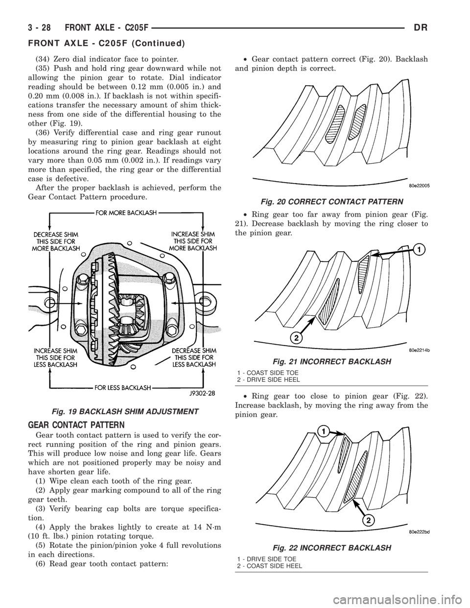
other (Fig. 19).
(36) Verify differential case and ring gear runout
by measuring ring to pinion gear backlash at eight
locations around the ring gear. Readings should not
vary more than 0.05 mm (0.002 in.). If readings vary
more than specified, the ring gear or the differential
case is defective.
After the proper backlash is achieved, perform the
Gear Contact Pattern procedure.
GEAR CONTACT PATTERN
Gear tooth contact pattern is used to verify the cor-
rect running position of the ring and pinion gears.
This will produce low noise and long gear life. Gears
which are not positioned properly may be noisy and
have shorten gear life.
(1) Wipe clean each tooth of the ring gear.
(2) Apply gear marking compound to all of the ring
gear teeth.
(3) Verify bearing cap bolts are torque specifica-
tion.
(4) Apply the brakes lightly to create at 14 N´m
(10 ft. lbs.) pinion rotating torque.
(5) Rotate the pinion/pinion yoke 4 full revolutions
in each directions.
(6) Read gear tooth contact pattern:²Gear contact pattern correct (Fig. 20). Backlash
and pinion depth is correct.
²Ring gear too far away from pinion gear (Fig.
21). Decrease backlash by moving the ring closer to
the pinion gear.
²Ring gear too close to pinion gear (Fig. 22).
Increase backlash, by moving the ring away from the
pinion gear.
Fig. 19 BACKLASH SHIM ADJUSTMENT
Fig. 20 CORRECT CONTACT PATTERN
Fig. 21 INCORRECT BACKLASH
1 - COAST SIDE TOE
2 - DRIVE SIDE HEEL
Fig. 22 INCORRECT BACKLASH
1 - DRIVE SIDE TOE
2 - COAST SIDE HEEL
3 - 28 FRONT AXLE - C205FDR
FRONT AXLE - C205F (Continued)
Page 108 of 2895
INSTALLATION
(1) Apply a light coating of gear lubricant on the
lip of pinion seal.
(2) Install seal with Installer 8695 and Handle
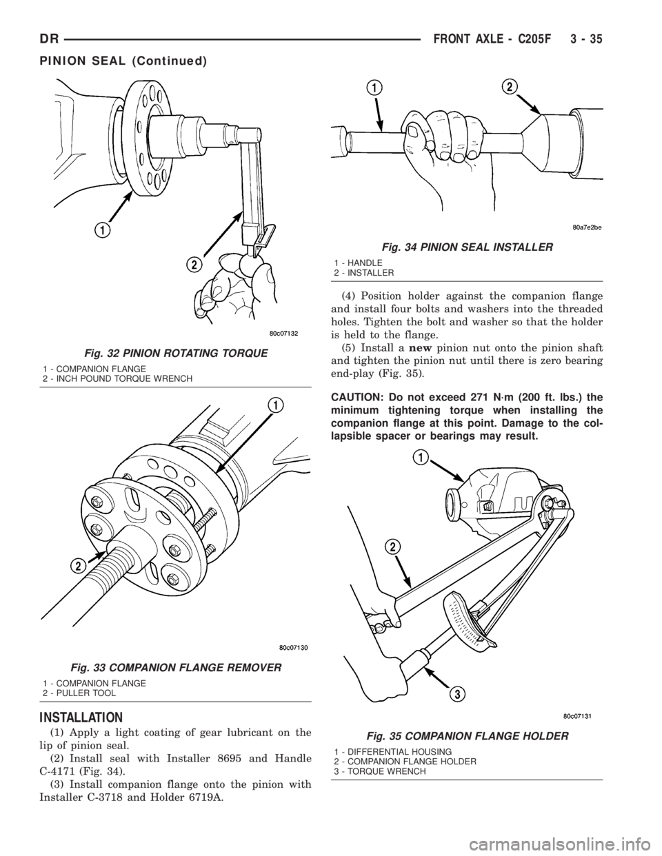
C-4171 (Fig. 34).
(3) Install companion flange onto the pinion with
Installer C-3718 and Holder 6719A.(4) Position holder against the companion flange
and install four bolts and washers into the threaded
holes. Tighten the bolt and washer so that the holder
is held to the flange.
(5) Install anewpinion nut onto the pinion shaft
and tighten the pinion nut until there is zero bearing
end-play (Fig. 35).
CAUTION: Do not exceed 271 N´m (200 ft. lbs.) the
minimum tightening torque when installing the
companion flange at this point. Damage to the col-
lapsible spacer or bearings may result.
Fig. 32 PINION ROTATING TORQUE
1 - COMPANION FLANGE
2 - INCH POUND TORQUE WRENCH
Fig. 33 COMPANION FLANGE REMOVER
1 - COMPANION FLANGE
2 - PULLER TOOL
Fig. 34 PINION SEAL INSTALLER
1 - HANDLE
2 - INSTALLER
Fig. 35 COMPANION FLANGE HOLDER
1 - DIFFERENTIAL HOUSING
2 - COMPANION FLANGE HOLDER
3 - TORQUE WRENCH
DRFRONT AXLE - C205F 3 - 35
PINION SEAL (Continued)
Page 115 of 2895

INSTALLATION
NOTE: The ring gear and pinion are serviced in a
matched set. Never replace one gear without replac-
ing the other matching gear. If ring and pinion
gears or bearings are replaced, Refer to Adjust-
ments for Pinion Gear Depth Setting.
(1) Apply Mopar Door Ease or equivalent lubricant
to outside surface of the bearing cups.
(2) Install rear pinion bearing cup with Installer
8692 and Driver Handle C-4171 (Fig. 53) and verify
cup is seated.(3) Install front pinion bearing cup with Installer
8693 and Handle C-4171 (Fig. 54) and verify cup is
seated.
(4) Lubricate front pinion bearing and install bear-
ing in the housing.
(5) Apply a light coating of gear lubricant on the
lip of pinion seal.
(6) Install pinion seal with Installer 8695 and
Handle C-4171 (Fig. 55).
Fig. 53 REAR PINION BEARING CUP
1 - HOUSING
2 - INSTALLER
3 - HANDLE
Fig. 54 FRONT PINION BEARING CUP
1 - HOUSING
2 - INSTALLER
3 - HANDLE
Fig. 55 PINION SEAL
1 - HANDLE
2 - INSTALLER
3 - 42 FRONT AXLE - C205FDR
PINION GEAR/RING GEAR (Continued)
Page 119 of 2895
heard during a coast, the front pinion bearing is the
source.
Worn or damaged differential bearings usually pro-
duce a low pitch noise. Differential bearing noise is
similar to pinion bearing noise. The pitch of differen-
tial bearing noise is also constant and varies only
with vehicle speed.
Axle shaft bearings produce noise and vibration
when worn or damaged. The noise generally changes
when the bearings are loaded. Road test the vehicle.
Turn the vehicle sharply to the left and to the right.
This will load the bearings and change the noise
level. Where axle bearing damage is slight, the noise
is usually not noticeable at speeds above 30 mph.
LOW SPEED KNOCK
Low speed knock is generally caused by a worn
U-joint or by worn side-gear thrust washers. A worn
pinion shaft bore will also cause low speed knock.
VIBRATION
Vibration at the front/rear of the vehicle is usually
caused by:
²Damaged drive shaft.
²Missing drive shaft balance weight(s).
²Worn or out of balance wheels.
²Loose wheel lug nuts.
²Worn U-joint(s).²Loose/broken springs.
²Damaged axle shaft bearing(s).
²Loose pinion gear nut.
²Excessive pinion yoke run out.
²Bent axle shaft(s).
Check for loose or damaged front end components
or engine/transmission mounts. These components
can contribute to what appears to be a vibration. Do
not overlook engine accessories, brackets and drive
belts.
DRIVELINE SNAP
A snap or clunk noise when the vehicle is shifted
into gear (or the clutch engaged) can be caused by:
²High engine idle speed.
²Transmission shift operation.
²Loose engine/transmission/transfer case mounts.
²Worn U-joints.
²Loose spring mounts.
²Loose pinion gear nut and yoke.
²Excessive ring gear backlash.
²Excessive side gear to case clearance.
The source of a snap or a clunk noise can be deter-
mined with the assistance of a helper. Raise the vehi-
cle on a hoist with the wheels free to rotate. Instruct
the helper to shift the transmission into gear. Listen
for the noise, a mechanics stethoscope is helpful in
isolating the source of a noise.
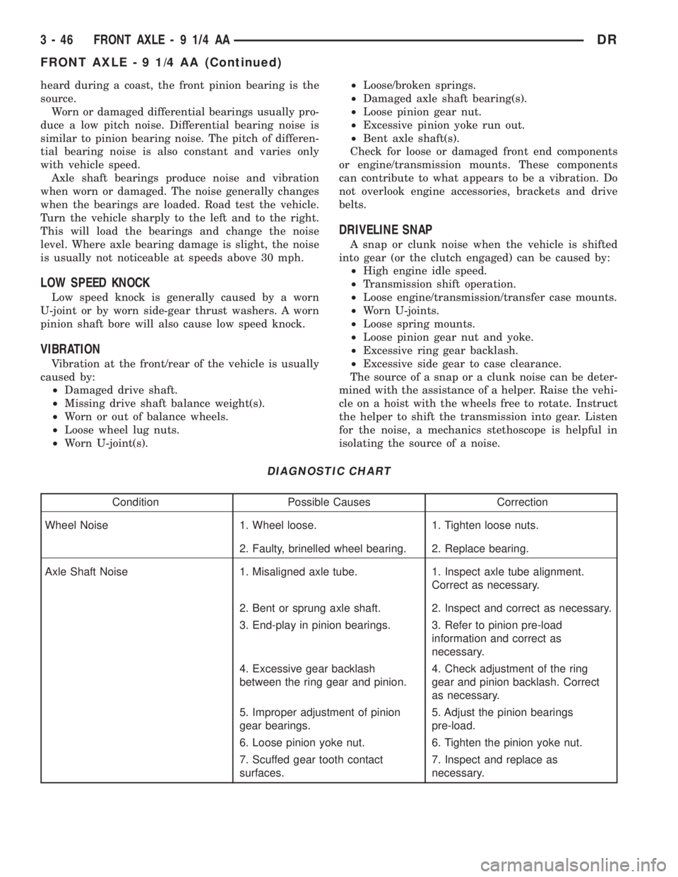
DIAGNOSTIC CHART
Condition Possible Causes Correction
Wheel Noise 1. Wheel loose. 1. Tighten loose nuts.
2. Faulty, brinelled wheel bearing. 2. Replace bearing.
Axle Shaft Noise 1. Misaligned axle tube. 1. Inspect axle tube alignment.
Correct as necessary.
2. Bent or sprung axle shaft. 2. Inspect and correct as necessary.
3. End-play in pinion bearings. 3. Refer to pinion pre-load
information and correct as
necessary.
4. Excessive gear backlash
between the ring gear and pinion.4. Check adjustment of the ring
gear and pinion backlash. Correct
as necessary.
5. Improper adjustment of pinion
gear bearings.5. Adjust the pinion bearings
pre-load.
6. Loose pinion yoke nut. 6. Tighten the pinion yoke nut.
7. Scuffed gear tooth contact
surfaces.7. Inspect and replace as
necessary.
3 - 46 FRONT AXLE - 9 1/4 AADR
FRONT AXLE - 9 1/4 AA (Continued)
Page 124 of 2895
(6) Install ring gear side adjuster lock and bolt. Do
not tighten adjuster lock bolt at this time.
(7) Tighten pinion gear side adjuster firmly
against the differential case bearing cup.
(8) Rotate the pinion several times to seat the dif-
ferential bearings.
(9) Loosen pinion gear side adjuster until it is no
longer in contact with the bearing cup, then tighten
it until it makes contact.
(10) Tighten pinion gear side adjuster an addi-
tional:
²New Bearings:6 Adjuster Holes
²Original Bearings:4 Adjuster Holes
(11) Install pinion gear side adjuster lock and bolt.
Do not tighten adjuster lock bolt at this time.
(12) Tighten bearing cap bolts to 85 N´m (63 ft.
lbs.).
(13) Tighten adjuster lock bolts to 25 N´m (18 ft.
lbs.).
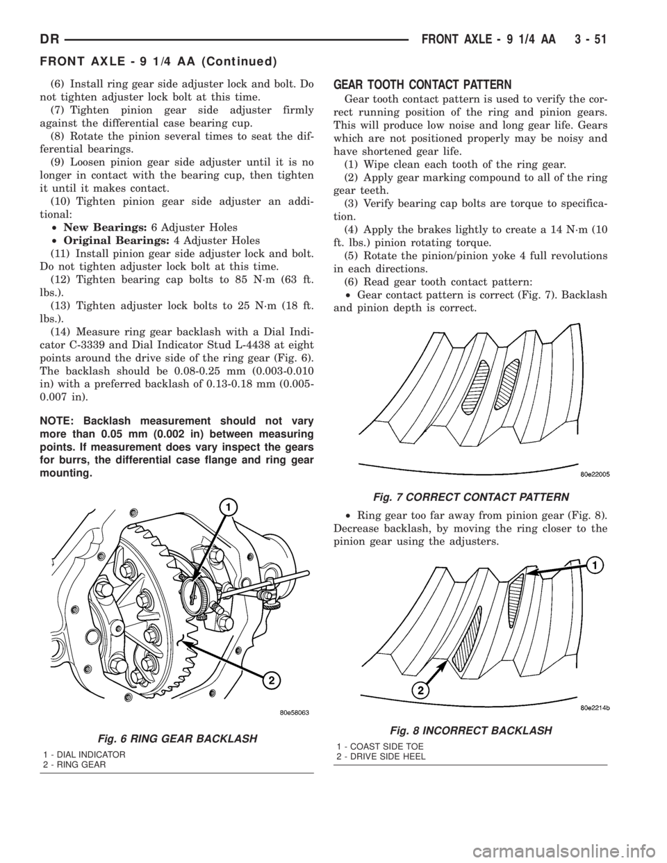
(14) Measure ring gear backlash with a Dial Indi-
cator C-3339 and Dial Indicator Stud L-4438 at eight
points around the drive side of the ring gear (Fig. 6).
The backlash should be 0.08-0.25 mm (0.003-0.010
in) with a preferred backlash of 0.13-0.18 mm (0.005-
0.007 in).
NOTE: Backlash measurement should not vary
more than 0.05 mm (0.002 in) between measuring
points. If measurement does vary inspect the gears
for burrs, the differential case flange and ring gear
mounting.GEAR TOOTH CONTACT PATTERN
Gear tooth contact pattern is used to verify the cor-
rect running position of the ring and pinion gears.
This will produce low noise and long gear life. Gears
which are not positioned properly may be noisy and
have shortened gear life.
(1) Wipe clean each tooth of the ring gear.
(2) Apply gear marking compound to all of the ring
gear teeth.
(3) Verify bearing cap bolts are torque to specifica-
tion.
(4) Apply the brakes lightly to create a 14 N´m (10
ft. lbs.) pinion rotating torque.
(5) Rotate the pinion/pinion yoke 4 full revolutions
in each directions.
(6) Read gear tooth contact pattern:
²Gear contact pattern is correct (Fig. 7). Backlash
and pinion depth is correct.
²Ring gear too far away from pinion gear (Fig. 8).
Decrease backlash, by moving the ring closer to the
pinion gear using the adjusters.
Fig. 6 RING GEAR BACKLASH
1 - DIAL INDICATOR
2 - RING GEAR
Fig. 7 CORRECT CONTACT PATTERN
Fig. 8 INCORRECT BACKLASH
1 - COAST SIDE TOE
2 - DRIVE SIDE HEEL
DRFRONT AXLE - 9 1/4 AA 3 - 51
FRONT AXLE - 9 1/4 AA (Continued)
Page 133 of 2895
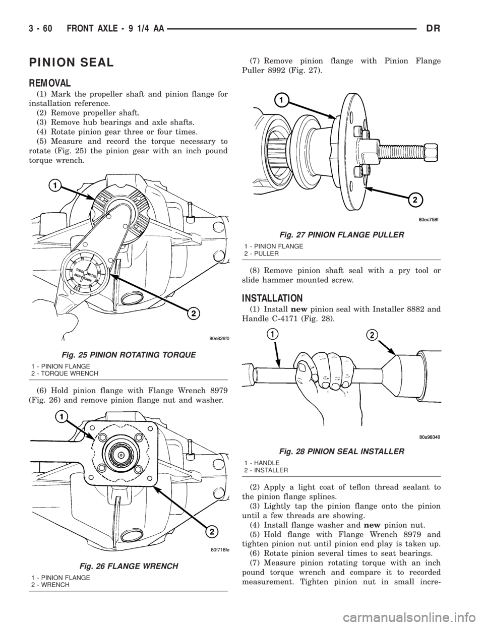
PINION SEAL
REMOVAL
(1) Mark the propeller shaft and pinion flange for
installation reference.
(2) Remove propeller shaft.
(3) Remove hub bearings and axle shafts.
(4) Rotate pinion gear three or four times.
(5) Measure and record the torque necessary to
rotate (Fig. 25) the pinion gear with an inch pound
torque wrench.
(6) Hold pinion flange with Flange Wrench 8979
(Fig. 26) and remove pinion flange nut and washer.(7) Remove pinion flange with Pinion Flange
Puller 8992 (Fig. 27).
(8) Remove pinion shaft seal with a pry tool or
slide hammer mounted screw.
INSTALLATION
(1) Installnewpinion seal with Installer 8882 and
Handle C-4171 (Fig. 28).
(2) Apply a light coat of teflon thread sealant to
the pinion flange splines.
(3) Lightly tap the pinion flange onto the pinion
until a few threads are showing.
(4) Install flange washer andnewpinion nut.
(5) Hold flange with Flange Wrench 8979 and
tighten pinion nut until pinion end play is taken up.
(6) Rotate pinion several times to seat bearings.
(7) Measure pinion rotating torque with an inch
pound torque wrench and compare it to recorded
measurement. Tighten pinion nut in small incre-
Fig. 25 PINION ROTATING TORQUE
1 - PINION FLANGE
2 - TORQUE WRENCH
Fig. 26 FLANGE WRENCH
1 - PINION FLANGE
2 - WRENCH
Fig. 27 PINION FLANGE PULLER
1 - PINION FLANGE
2 - PULLER
Fig. 28 PINION SEAL INSTALLER
1 - HANDLE
2 - INSTALLER
3 - 60 FRONT AXLE - 9 1/4 AADR
Page 136 of 2895
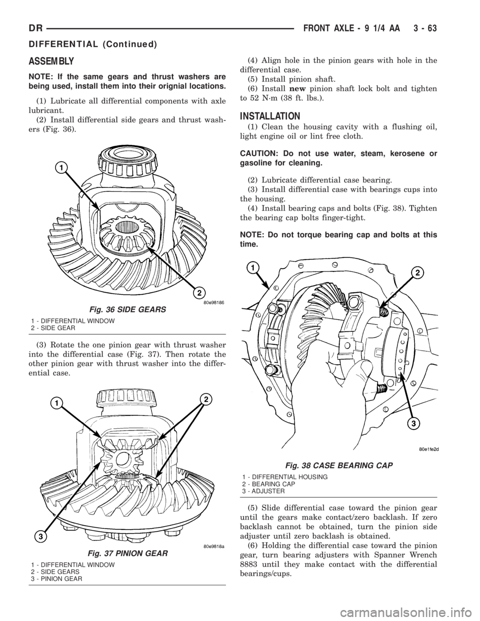
ASSEMBLY
NOTE: If the same gears and thrust washers are
being used, install them into their orignial locations.
(1) Lubricate all differential components with axle
lubricant.
(2) Install differential side gears and thrust wash-
ers (Fig. 36).
(3) Rotate the one pinion gear with thrust washer
into the differential case (Fig. 37). Then rotate the
other pinion gear with thrust washer into the differ-
ential case.(4) Align hole in the pinion gears with hole in the
differential case.
(5) Install pinion shaft.
(6) Installnewpinion shaft lock bolt and tighten
to 52 N´m (38 ft. lbs.).
INSTALLATION
(1) Clean the housing cavity with a flushing oil,
light engine oil or lint free cloth.
CAUTION: Do not use water, steam, kerosene or
gasoline for cleaning.
(2) Lubricate differential case bearing.
(3) Install differential case with bearings cups into
the housing.
(4) Install bearing caps and bolts (Fig. 38). Tighten
the bearing cap bolts finger-tight.
NOTE: Do not torque bearing cap and bolts at this
time.
(5) Slide differential case toward the pinion gear
until the gears make contact/zero backlash. If zero
backlash cannot be obtained, turn the pinion side
adjuster until zero backlash is obtained.
(6) Holding the differential case toward the pinion
gear, turn bearing adjusters with Spanner Wrench
8883 until they make contact with the differential
bearings/cups.
Fig. 36 SIDE GEARS
1 - DIFFERENTIAL WINDOW
2 - SIDE GEAR
Fig. 37 PINION GEAR
1 - DIFFERENTIAL WINDOW
2 - SIDE GEARS
3 - PINION GEAR
Fig. 38 CASE BEARING CAP
1 - DIFFERENTIAL HOUSING
2 - BEARING CAP
3 - ADJUSTER
DRFRONT AXLE - 9 1/4 AA 3 - 63
DIFFERENTIAL (Continued)
Page 141 of 2895

(7) Install pinion into the housing and place front
pinion bearing onto the pinion shaft. Draw the pinion
shaft into the front bearing with Installer 8982 (Fig.
52).
(8) Installnewpinion seal (Fig. 53) with Installer
8882 and Handle C-4171.
(9) Apply a light coat of teflon sealant to the pin-
ion flange splines.
(10) Hold pinion and lightly tap the pinion flange
onto the pinion shaft, until a few threads are show-
ing.
(11) Install pinion flange washer andnewpinion
nut.
(12) Hold pinion flange with Flange Wrench 8979
and tighten pinion nut until end play is taken up.
(13) Rotate pinion several times to seat bearings.
(14) Measure pinion rotating torque with an inch
pound torque wrench (Fig. 54). Tighten pinion nut in
small increments until pinion rotating torque is:²New Pinion Bearings:1.7-2.8 N´m (15-25 in.
lbs.)
²Original Pinion Bearings:1.1-2.2 N´m (10-20
in. lbs.)
(15) Rotate pinion several times then verify pinion
rotating torque again.
(16) Position the ring gear on differential case and
start twonewring gear bolts.
(17) Install the rest of thenewring gear bolts and
tighten them alternately to seat the ring gear.
(18) Torque ring gear bolts to 140 N´m (103 ft.
lbs.).
(19) Install differential in housing.
(20) Measure final rotating torque with an inch
pound torque wrench. The final pinion rotating
torque plus differential case bearing preload is:
²New Bearings:3.4-5.6 N´m (30-50 in. lbs.)
²Original Bearings:2.8-5.1 N´m (25-45 in. lbs.)
(21) Install axle shafts.
(22) Verify ring gear backlash and gear contact
pattern.
(23) Install the propeller shaft with the reference
marks aligned.
(24) Install differential cover with gasket and
tighten to 40 N´m (30 ft. lbs.).
(25) Fill differential with fluid and tighten fill plug
to 32 N´m (24 ft. lbs.).
Fig. 52 PINION GEAR INSTALLER
1 - INSTALLER
2 - DIFFERENTIAL HOUSING
Fig. 53 PINION SEAL INSTALLER
1 - HANDLE
2 - INSTALLER
Fig. 54 PINION ROTATING TORQUE
1 - PINION FLANGE
2 - TORQUE WRENCH
3 - 68 FRONT AXLE - 9 1/4 AADR
PINION GEAR/RING GEAR (Continued)