2003 DODGE RAM intake manifold temperature sensor
[x] Cancel search: intake manifold temperature sensorPage 392 of 2895

OPERATION
OPERATION - PCM
The PCM operates the fuel system. The PCM is a
pre-programmed, triple microprocessor digital com-
puter. It regulates ignition timing, air-fuel ratio,
emission control devices, charging system, certain
transmission features, speed control, air conditioning
compressor clutch engagement and idle speed. The
PCM can adapt its programming to meet changing
operating conditions.
The PCM receives input signals from various
switches and sensors. Based on these inputs, the
PCM regulates various engine and vehicle operations
through different system components. These compo-
nents are referred to as Powertrain Control Module
(PCM) Outputs. The sensors and switches that pro-
vide inputs to the PCM are considered Powertrain
Control Module (PCM) Inputs.
The PCM adjusts ignition timing based upon
inputs it receives from sensors that react to: engine
rpm, manifold absolute pressure, engine coolant tem-
perature, throttle position, transmission gear selec-
tion (automatic transmission), vehicle speed, power
steering pump pressure, and the brake switch.
The PCM adjusts idle speed based on inputs it
receives from sensors that react to: throttle position,
vehicle speed, transmission gear selection, engine
coolant temperature and from inputs it receives from
the air conditioning clutch switch and brake switch.
Based on inputs that it receives, the PCM adjusts
ignition coil dwell. The PCM also adjusts the gener-
ator charge rate through control of the generator
field and provides speed control operation.
NOTE: PCM Inputs:
²ABS module (if equipped)
²A/C request (if equipped with factory A/C)
²A/C select (if equipped with factory A/C)
²A/C pressure transducer
²Auto shutdown (ASD) sense
²Battery temperature sensor
²Battery voltage
²Brake switch
²J1850 bus (+) circuits
²J1850 bus (-) circuits
²Camshaft position sensor signal
²Crankshaft position sensor
²Data link connection for DRB scan tool
²EATX module (if equipped)
²Engine coolant temperature sensor
²Fuel level (through J1850 circuitry)
²Generator (battery voltage) output
²Ignition circuit sense (ignition switch in on/off/
crank/run position)²Intake manifold air temperature sensor
²Knock sensors (2 on 3.7L engine)
²Leak detection pump (switch) sense (if equipped)
²Manifold absolute pressure (MAP) sensor
²Oil pressure
²Oxygen sensors
²Park/neutral switch (auto. trans. only)
²Power ground
²Power steering pressure switch (if equipped)
²Sensor return
²Signal ground
²Speed control multiplexed single wire input
²Throttle position sensor
²Transfer case switch (4WD range position)
²Vehicle speed signal
NOTE: PCM Outputs:
²A/C clutch relay
²Auto shutdown (ASD) relay
²J1850 bus (+/-) circuits for: speedometer, voltme-
ter, fuel gauge, oil pressure gauge/lamp, engine temp.
gauge and speed control warn. lamp
²Data link connection for DRB scan tool
²EGR valve control solenoid (if equipped)
²EVAP canister purge solenoid
²Five volt sensor supply (primary)
²Five volt sensor supply (secondary)
²Fuel injectors
²Fuel pump relay
²Generator field driver (-)
²Generator field driver (+)
²Idle air control (IAC) motor
²Ignition coil(s)
²Leak detection pump (if equipped)
²Malfunction indicator lamp (Check engine lamp).
Driven through J1850 circuits.
²Oxygen sensor heater relays
²Oxygen sensors (pulse width modulated)
²Radiator cooling fan relay (pulse width modu-
lated)
²Speed control vacuum solenoid
²Speed control vent solenoid
²Tachometer (if equipped). Driven through J1850
circuits.
²Transmission convertor clutch circuit. Driven
through J1850 circuits.
OPERATION - 5 VOLT SUPPLIES
Primary 5±volt supply:
²supplies the required 5 volt power source to the
Crankshaft Position (CKP) sensor.
²supplies the required 5 volt power source to the
Camshaft Position (CMP) sensor.
²supplies a reference voltage for the Manifold
Absolute Pressure (MAP) sensor.
DRELECTRONIC CONTROL MODULES 8E - 11
POWERTRAIN CONTROL MODULE (Continued)
Page 480 of 2895

The PCM adjusts ignition timing based on inputs it
receives from:
²The engine coolant temperature sensor
²The crankshaft position sensor (engine speed)
²The camshaft position sensor (crankshaft posi-
tion)
²The manifold absolute pressure (MAP) sensor
²The throttle position sensor
²Transmission gear selection
REMOVAL
3.7L V-6
An individual ignition coil is used for each spark
plug (Fig. 30). The coil fits into machined holes in the
cylinder head. A mounting stud/nut secures each coil
to the top of the intake manifold (Fig. 31). The bot-
tom of the coil is equipped with a rubber boot to seal
the spark plug to the coil. Inside each rubber boot is
a spring. The spring is used for a mechanical contact
between the coil and the top of the spark plug. These
rubber boots and springs are a permanent part of the
coil and are not serviced separately. An o-ring (Fig.
30) is used to seal the coil at the opening into the cyl-
inder head.
(1) Depending on which coil is being removed, the
throttle body air intake tube or intake box may need
to be removed to gain access to coil.
(2) Disconnect electrical connector from coil by
pushing downward on release lock on top of connec-
tor and pull connector from coil.
(3) Clean area at base of coil with compressed air
before removal.
(4) Remove coil mounting nut from mounting stud
(Fig. 31).
(5) Carefully pull up coil from cylinder head open-
ing with a slight twisting action.
(6) Remove coil from vehicle.
4.7L V-8
An individual ignition coil is used for each spark
plug (Fig. 30). The coil fits into machined holes in the
cylinder head. A mounting stud/nut secures each coil
to the top of the intake manifold (Fig. 32). The bot-
tom of the coil is equipped with a rubber boot to seal
the spark plug to the coil. Inside each rubber boot is
a spring. The spring is used for a mechanical contact
between the coil and the top of the spark plug. These
rubber boots and springs are a permanent part of the
coil and are not serviced separately. An o-ring (Fig.
30) is used to seal the coil at the opening into the cyl-
inder head.
(1) Depending on which coil is being removed, the
throttle body air intake tube or intake box may need
to be removed to gain access to coil.(2) Disconnect electrical connector (Fig. 32) from
coil by pushing downward on release lock on top of
connector and pull connector from coil.
(3) Clean area at base of coil with compressed air
before removal.
(4) Remove coil mounting nut from mounting stud
(Fig. 32).
(5) Carefully pull up coil from cylinder head open-
ing with a slight twisting action.
(6) Remove coil from vehicle.
5.7L V-8
Before removing or disconnecting any spark plug
cables, note their original position. Remove cables
one-at-a-time. To prevent ignition crossfire, spark
plug cablesMUSTbe placed in cable tray (routing
loom) into their original position.
An individual ignition coil (Fig. 33) is used at each
cylinder. The coil mounts to the top of the valve cover
with 2 bolts (Fig. 34). The bottom of the coil is
equipped with a rubber boot to seal the spark plug to
the coil. Inside each rubber boot is a spring. The
spring is used for a mechanical contact between the
coil and the top of the spark plug.
(1) Depending on which coil is being removed, the
throttle body air intake tube or intake box may need
to be removed to gain access to coil.
(2) Unlock electrical connector (Fig. 34) by moving
slide lock first. Press on release lock (Fig. 34) while
pulling electrical connector from coil.
(3) Disconnect secondary high-voltage cable from
coil with a twisting action.
(4) Clean area at base of coil with compressed air
before removal.
(5) Remove 2 mounting bolts (note that mounting
bolts are retained to coil).
(6) Carefully pull up coil from cylinder head open-
ing with a slight twisting action.
(7) Remove coil from vehicle.
(8) Before installing spark plug cables to either the
spark plugs or coils, or before installing a coil to a
spark plug, apply dielectric grease to inside of boots.
5.9L V-8
The coil is not oil filled. The coil windings are
embedded in an epoxy compound. This provides heat
and vibration resistance that allows the coil to be
mounted on the engine. If the coil is replaced, it must
be replaced with the same type.
5.9L V-8 LDC-Gas Engines: The coil is mounted to
a bracket that is bolted to the front of the right
engine cylinder head (Fig. 35). This bracket is
mounted on top of the automatic belt tensioner
bracket using common bolts.
DRIGNITION CONTROL 8I - 23
IGNITION COIL (Continued)
Page 535 of 2895

WAIT-TO-START INDICATOR
DESCRIPTION
A wait-to-start indicator is only found in the
instrument clusters for vehicles equipped with an
optional diesel engine. The wait-to-start indicator is
located near the lower edge of the instrument cluster,
between the tachometer and the speedometer. The
wait-to-start indicator consists of stencil-like cutout
of the International Control and Display Symbol icon
for ªDiesel Preheatº in the opaque layer of the instru-
ment cluster overlay. The dark outer layer of the
overlay prevents the indicator from being clearly vis-
ible when it is not illuminated. An amber Light
Emitting Diode (LED) behind the cutout in the
opaque layer of the overlay causes the icon to appear
in amber through the translucent outer layer of the
overlay when the indicator is illuminated from
behind by the LED, which is soldered onto the
instrument cluster electronic circuit board. The wait-
to-start indicator is serviced as a unit with the
instrument cluster.
OPERATION
The wait-to-start indicator gives an indication to
the vehicle operator when the air temperature within
the diesel engine intake manifold is too cool for effi-
cient and reliable engine starting, and that the
intake air heater grids are energized in their pre-
heat operating mode. This indicator is controlled by a
transistor on the instrument cluster circuit board
based upon cluster programming and electronic mes-
sages received by the cluster from the Engine Control
Module (ECM) over the Programmable Communica-
tions Interface (PCI) data bus. The wait-to-start indi-
cator Light Emitting Diode (LED) is completely
controlled by the instrument cluster logic circuit, and
that logic will only allow this indicator to operate
when the instrument cluster receives a battery cur-
rent input on the fused ignition switch output (run-
start) circuit. Therefore, the LED will always be off
when the ignition switch is in any position except On
or Start. The LED only illuminates when it is pro-
vided a path to ground by the instrument cluster
transistor. The instrument cluster will turn on the
wait-to-start indicator for the following reasons:
²Wait-To-Start Lamp-On Message- Each time
the cluster receives a wait-to-start lamp-on message
from the ECM indicating that the air temperature
within the intake manifold is too cool for efficient
and reliable engine starting, the wait-to-start indica-
tor will be illuminated. The indicator remains illumi-
nated until the cluster receives a wait-to-start lamp-
off message, until the ECM detects that the engine is
running or until the ignition switch is turned to the
Off position, whichever occurs first.²Actuator Test- Each time the cluster is put
through the actuator test, the wait-to-start indicator
will be turned on, then off again during the bulb
check portion of the test to confirm the functionality
of the LED and the cluster control circuitry.
The ECM continually monitors the engine intake
air temperature sensor to determine when the intake
air heater grids should be energized in their pre-heat
operating mode. The ECM then sends the proper
wait-to-start lamp-on and lamp-off messages to the
instrument cluster. For further diagnosis of the wait-
to-start indicator or the instrument cluster circuitry
that controls the indicator, (Refer to 8 - ELECTRI-
CAL/INSTRUMENT CLUSTER - DIAGNOSIS AND
TESTING). For proper diagnosis of the engine intake
air temperature sensor, the intake air heater grid
control circuits, the ECM, the PCI data bus, or the
electronic message inputs to the instrument cluster
that control the wait-to-start indicator, a DRBIIIt
scan tool is required. Refer to the appropriate diag-
nostic information.
WASHER FLUID INDICATOR
DESCRIPTION
A washer fluid indicator is standard equipment on
all instrument clusters. The washer fluid indicator
consists of the words ªLOW WASHº, which appear in
the lower portion of the odometer/trip odometer Vac-
uum-Fluorescent Display (VFD) unit. The VFD is sol-
dered onto the cluster electronic circuit board and is
visible through a window with a smoked clear lens
located on the lower edge of the tachometer gauge
dial face of the cluster overlay. The dark lens over
the VFD prevents the indicator from being clearly
visible when it is not illuminated. The ªLOW WASHº
text appears in an amber color and at the same light-
ing level as the odometer/trip odometer information
when it is illuminated by the instrument cluster elec-
tronic circuit board. The washer fluid indicator is ser-
viced as a unit with the VFD in the instrument
cluster.
OPERATION
The washer fluid indicator gives an indication to
the vehicle operator that the fluid level in the washer
reservoir is low. This indicator is controlled by the
instrument cluster circuit board based upon cluster
programming and electronic messages received by
the cluster from the Front Control Module (FCM)
over the Programmable Communications Interface
(PCI) data bus. The washer fluid indicator is com-
pletely controlled by the instrument cluster logic cir-
cuit, and that logic will only allow this indicator to
operate when the instrument cluster receives a bat-
8J - 42 INSTRUMENT CLUSTERDR
Page 720 of 2895

8W-02 COMPONENT INDEX
Component Page
4WD Switch......................... 8W-30
A/C Compressor Clutch Relay............ 8W-42
A/C Compressor Clutch................. 8W-42
A/C Pressure Transducer................ 8W-42
A/C-Heater Control.................... 8W-42
Accelerator Pedal Position Sensor......... 8W-30
Adjustable Pedal Motor................. 8W-30
Adjustable Pedal Relay................. 8W-30
Adjustable Pedal Switch................ 8W-30
Airbag Control Modules................ 8W-43
Airbags............................. 8W-43
Ambient Temperature Sensor............ 8W-49
Amplifier Audio....................... 8W-47
Auto Shut Down Relay................. 8W-30
Automatic Day/Night Mirror............. 8W-49
Auxiliary Battery..................... 8W-20
Backup Lamp Switch.................. 8W-51
Battery Temperature Sensor............. 8W-30
Battery............................. 8W-20
Blend Door Actuator................... 8W-42
Blower Motor Resistor Block............. 8W-42
Blower Motor......................... 8W-42
Brake Lamp Switch.................... 8W-33
Brake Transmission Shift Interlock
Solenoid........................... 8W-40
Camshaft Position Sensor............... 8W-30
Capacitor............................ 8W-30
Center High Mounted Stop Lamp/Cargo
Lamp.......................... 8W-44, 51
Center High Mounted Stop Lamp-
Aftermarket..................... 8W-33, 51
Cigar Lighter Outlet................... 8W-41
Circuit Breaker....................... 8W-10
Clearance Lamps...................... 8W-50
Clockspring................. 8W-33, 41, 43, 47
Clutch Interlock Brake Switch........... 8W-21
Coil On Plugs........................ 8W-30
Compass/Mini-Trip Computer............ 8W-49
Condenser Fan Relay.................. 8W-42
Condenser Fan....................... 8W-42
Controller Antilock Brake............ 8W-34, 35
Crankshaft Position Sensor.............. 8W-30
Cylinder Lock Switch-Driver............. 8W-61
Cylinder Lock Switch-Passenger.......... 8W-61
Data Link Connector................... 8W-18
Data Link Connector-Engine............. 8W-18
Dome Lamp.......................... 8W-44
Door Ajar Switches.................... 8W-40
Door Lock Motor/Ajar Switches........ 8W-40, 61
Door Lock Switch-Passenger............. 8W-61
Driver Door Module.............. 8W-60, 61, 62
Electric Brake Provision............. 8W-33, 54Component Page
Electronic Throttle Control Module........ 8W-30
Engine Control Module................. 8W-30
Engine Coolant Temperature Sensor....... 8W-30
Engine Oil Pressure Switch.............. 8W-30
EVAP/Purge Solenoid.................. 8W-30
Evaporator Temperature Sensor.......... 8W-42
Fender Lamps........................ 8W-51
Fog Lamp Relay...................... 8W-50
Fog Lamps.......................... 8W-50
Front Control Module.................. 8W-10
Fuel Heater Relay..................... 8W-30
Fuel Heater.......................... 8W-30
Fuel Injectors........................ 8W-30
Fuel Injector Packs.................... 8W-30
Fuel Pump Module.................... 8W-30
Fuel Pump Motor..................... 8W-30
Fuel Pump Relay...................... 8W-30
Fuel Rail Pressure Sensor............... 8W-30
Fuses............................... 8W-10
Fusible Link......................... 8W-10
Grounds............................ 8W-15
Generator........................... 8W-20
Glove Box Lamp And Switch............. 8W-44
Headlamp Switch.................. 8W-40, 50
Headlamps.......................... 8W-50
Heated Mirror Relay................... 8W-62
Heated Seat Cushions.................. 8W-63
Heated Seat Switches.................. 8W-63
Horn Relay.......................... 8W-41
Horn Switch......................... 8W-41
Horns.............................. 8W-41
Idle Air Control Motor............ 8W-30, 30-36
Ignition Coils......................... 8W-30
Ignition Switch....................... 8W-10
Inlet Air Temperature/Pressure Sensor..... 8W-30
Input Speed Sensor.................... 8W-31
Instrument Cluster.................... 8W-40
Intake Air Heater Relays............... 8W-30
Intake Air Temperature Sensor........... 8W-30
Intake Air Temperature/Manifold Absolute
Pressure Sensor..................... 8W-30
Integrated Power Module............... 8W-10
Knock Sensors........................ 8W-30
Leak Detection Pump.................. 8W-30
License Lamps....................... 8W-51
Lift Pump Motor...................... 8W-30
Line Pressure Sensor................ 8W-30, 31
Lumbar Motors....................... 8W-63
Manifold Absolute Pressure Sensor........ 8W-30
Mode Door Actuators................... 8W-42
Multi-Function Switch............ 8W-40, 52, 53
Output Speed Sensor................... 8W-31
DR8W-02 COMPONENT INDEX 8W - 02 - 1
Page 816 of 2895

8W-30 FUEL/IGNITION SYSTEM
Component PageA/C Compressor Clutch Relay...........8W-30-27, 36, 83
A/C Pressure Transducer.......8W-30-19, 20, 21, 48, 53, 70
Accelerator Pedal Position Sensor.............8W-30-55
Adjustable Pedal Motor....................8W-30-87
Adjustable Pedal Relay....................8W-30-87
Adjustable Pedal Switch...................8W-30-87
Ambient Temperature Sensor................8W-30-56
Auto Shut Down Relay..................8W-30-4, 31
Battery..............................8W-30-77
Battery Temperature Sensor............8W-30-28, 39, 81
Brake Lamp Switch.............8W-30-25, 35, 65, 82, 89
Camshaft Position Sensor.......8W-30-17, 18, 37, 55, 70, 71
Capacitor.........................8W-30-6, 11, 43
Clockspring..................8W-30-25, 35, 65, 84, 90
Clutch Interlock Brake Switch...............8W-30-32
Coil On Plug No. 1...................8W-30-8, 42, 61
Coil On Plug No. 2...................8W-30-7, 40, 60
Coil On Plug No. 3...................8W-30-8, 42, 61
Coil On Plug No. 4...................8W-30-7, 40, 60
Coil On Plug No. 5...................8W-30-6, 41, 61
Coil On Plug No. 6...................8W-30-6, 43, 60
Coil On Plug No. 7....................8W-30-41, 61
Coil On Plug No. 8....................8W-30-43, 60
Condenser Fan Relay...................8W-30-27, 36
Controller Antilock Brake...........8W-30-23, 33, 38, 82
Crankshaft Position Sensor.............8W-30-17, 18, 37
Data Link Connector..........8W-30-27, 36, 46, 80, 89, 91
Data Link Connector-Engine................8W-30-75
Electronic Throttle Control Module............8W-30-63
Engine Control Module......8W-30-67, 68, 69, 70, 71, 72, 73,
74, 75, 76, 77, 78, 79, 80, 81, 82,
83, 84, 90, 91
Engine Coolant Temperature
Sensor.................8W-30-19, 20, 21, 48, 64, 72
Engine Oil Pressure Switch......8W-30-19, 20, 21, 29, 78, 81
EVAP/Purge Solenoid...................8W-30-28, 39
Front Control Module.....................8W-30-87
Fuel Heater...........................8W-30-85
Fuel Heater Relay.......................8W-30-85
Fuel Injector No. 1...............8W-30-8, 9, 11, 42, 62
Fuel Injector No. 2...............8W-30-7, 9, 12, 40, 59
Fuel Injector No. 3...............8W-30-8, 9, 11, 42, 62
Fuel Injector No. 4...............8W-30-7, 9, 12, 40, 60
Fuel Injector No. 5...............8W-30-6, 9, 11, 41, 62
Fuel Injector No. 6...............8W-30-6, 9, 12, 43, 59
Fuel Injector No. 7................8W-30-9, 11, 41, 62
Fuel Injector No. 8................8W-30-9, 12, 43, 59
Fuel Injector No. 9.......................8W-30-11
Fuel Injector No. 10......................8W-30-12
Fuel Injector Pack No. 1...................8W-30-67
Fuel Injector Pack No. 2..............8W-30-67, 68, 69
Fuel Injector Pack No. 3...................8W-30-69
Fuel Pump Module................8W-30-3, 30, 79, 83
Fuel Pump Motor.......................8W-30-76
Fuel Pump Relay......................8W-30-3, 30
Fuel Rail Pressure Sensor..................8W-30-74
Fuse 2.............................8W-30-4, 31
Fuse 5............................8W-30-50, 88
Fuse 12.............................8W-30-85
Fuse 17............................8W-30-3, 30
Fuse 19.......................8W-30-2, 29, 77, 90
Fuse 36...........................8W-30-79, 87
Fuse 40.............................8W-30-87
Fuse 49............................8W-30-4, 31
Fuse 50...........................8W-30-28, 88Component PageFusible Link..........................8W-30-77
G103.........................8W-30-3, 25, 30, 35
G104.........................8W-30-3, 25, 30, 35
G105.............................8W-30-81, 86
G106...............................8W-30-85
G107.........8W-30-2, 16, 24, 29, 34, 40, 42, 45, 47, 50, 54
G114 ...............................8W-30-78
G117 ...............................8W-30-91
G120.............................8W-30-75, 85
G201..........................8W-30-23, 33, 91
G203...............................8W-30-87
Generator.......................8W-30-24, 34, 75
Idle Air Control Motor..................8W-30-27, 36
Ignition Coil...........................8W-30-9
Ignition Coil-Left.......................8W-30-10
Ignition Coil-Right.......................8W-30-10
Ignition Switch....................8W-30-23, 33, 46
Inlet Air Temperature/Pressure Sensor..........8W-30-73
Input Speed Sensor......................8W-30-49
Intake Air Heater Relay No. 1...............8W-30-81
Intake Air Heater Relay No. 2...............8W-30-81
Intake Air Temperature Sensor......8W-30-19, 20, 21, 48, 64
Intake Air Temperature/Manifold Absolute Pressure
Sensor............................8W-30-74
Integrated Power Module . . 8W-30-2, 3, 4, 26, 27, 29, 30, 31, 36,
50, 77, 79, 80, 83, 85, 86, 87, 88, 90
Knock Sensor..........................8W-30-22
Knock Sensor-Left.......................8W-30-57
Knock Sensor-Right......................8W-30-57
Leak Detection Pump..................8W-30-24, 34
Lift Pump Motor........................8W-30-75
Line Pressure Sensor.....................8W-30-44
Manifold Absolute Pressure
Sensor.................8W-30-19, 20, 21, 48, 55, 64
Output Speed Sensor................8W-30-26, 49, 88
Overdrive Switch...................8W-30-23, 33, 91
Oxygen Sensor 1/1 Upstream.......8W-30-13, 14, 15, 47, 54
Oxygen Sensor 1/2 Downstream.....8W-30-13, 14, 16, 45, 54
Oxygen Sensor 2/1 Upstream..............8W-30-15, 47
Oxygen Sensor 2/2 Downstream............8W-30-16, 45
Oxygen Sensor Downstream Relay...........8W-30-4, 31
Power Steering Pressure Switch............8W-30-24, 34
Powertrain Control Module . . 8W-30-2, 3, 4, 5, 6, 7, 8, 9, 10, 11,
12, 13, 14, 15, 16 17, 18, 19, 20, 21, 22, 23, 24, 25, 27, 28, 29,
30, 31, 32, 33, 34, 35, 36, 37, 38, 39, 40, 41, 42, 43, 44, 45, 46,
47, 48, 49, 50, 51, 52, 53, 54, 55, 56, 57, 58, 59, 60, 61, 62, 63,
64, 65, 66, 77, 79, 82, 84, 85, 88, 89, 90, 91
PTCNo.1 ...........8W-30-2, 3, 27, 29, 30, 36, 80, 83, 86
PTO Switch.........................8W-30-23, 33
Speed Control Servo.................8W-30-25, 35, 89
Speed Control Switch-Left.............8W-30-65, 84, 90
Speed Control Switch-Right............8W-30-65, 84, 90
Starter Motor Relay......................8W-30-29
Throttle Position Sensor.................8W-30-22, 44
Throttle Position Switch...................8W-30-72
Transfer Case Control Module...............8W-30-65
Transmission Control Module.......8W-30-17, 23, 33, 38, 66
Transmission Control Relay............8W-30-26, 50, 88
Transmission Range Sensor..................8W-30-5
Transmission Solenoid Assembly.......8W-30-20, 21, 26, 88
Transmission Solenoid/TRS Assembly . . 8W-30-5, 32, 50, 51, 52
Vacuum Pump.........................8W-30-86
Vehicle Speed Sensor.....................8W-30-71
Vistronic Fan Drive......................8W-30-79
Water In Fuel Sensor...................8W-30-72, 76
DR8W-30 FUEL/IGNITION SYSTEM 8W - 30 - 1
Page 1070 of 2895
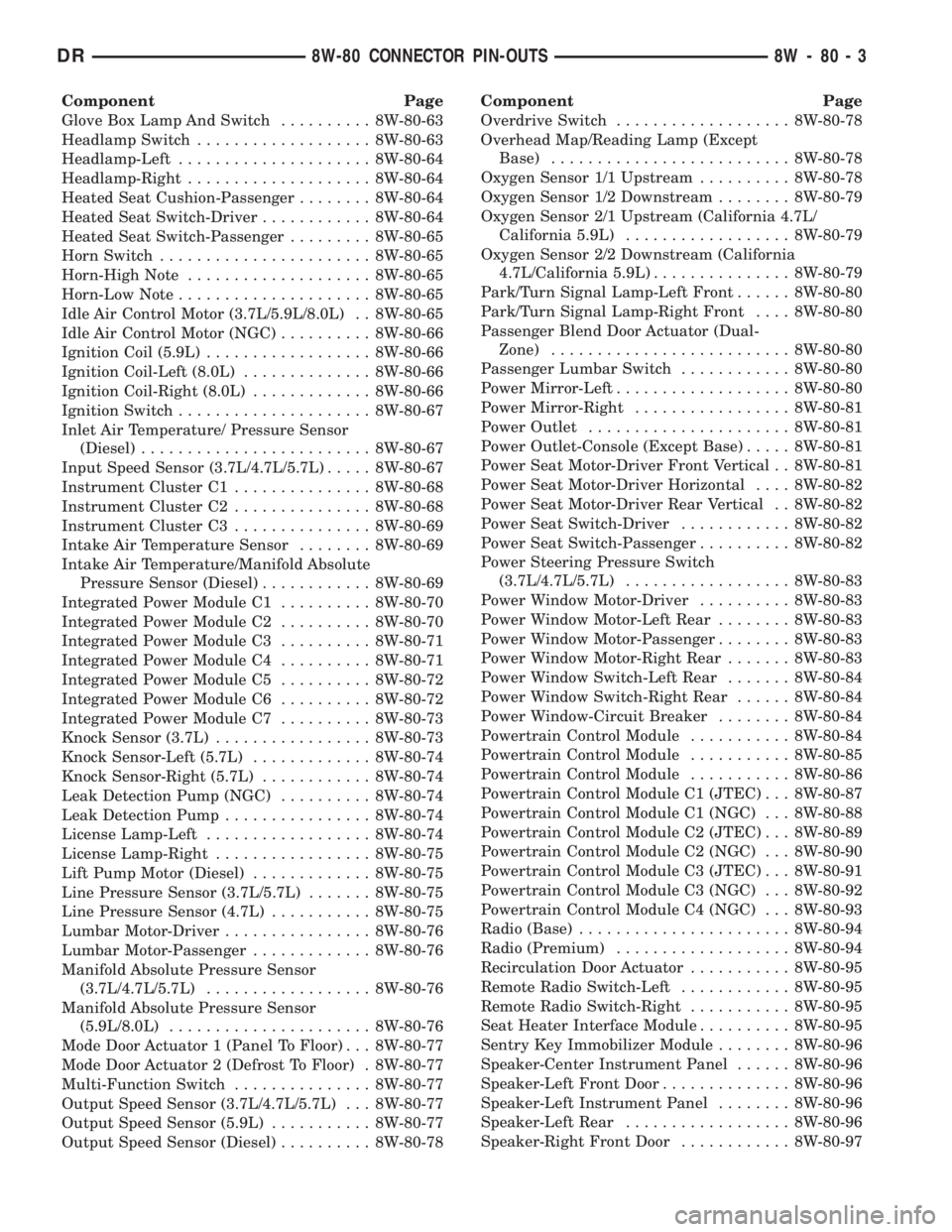
Component Page
Glove Box Lamp And Switch.......... 8W-80-63
Headlamp Switch................... 8W-80-63
Headlamp-Left..................... 8W-80-64
Headlamp-Right.................... 8W-80-64
Heated Seat Cushion-Passenger........ 8W-80-64
Heated Seat Switch-Driver............ 8W-80-64
Heated Seat Switch-Passenger......... 8W-80-65
Horn Switch....................... 8W-80-65
Horn-High Note.................... 8W-80-65
Horn-Low Note..................... 8W-80-65
Idle Air Control Motor (3.7L/5.9L/8.0L) . . 8W-80-65
Idle Air Control Motor (NGC).......... 8W-80-66
Ignition Coil (5.9L).................. 8W-80-66
Ignition Coil-Left (8.0L).............. 8W-80-66
Ignition Coil-Right (8.0L)............. 8W-80-66
Ignition Switch..................... 8W-80-67
Inlet Air Temperature/ Pressure Sensor
(Diesel)......................... 8W-80-67
Input Speed Sensor (3.7L/4.7L/5.7L)..... 8W-80-67
Instrument Cluster C1............... 8W-80-68
Instrument Cluster C2............... 8W-80-68
Instrument Cluster C3............... 8W-80-69
Intake Air Temperature Sensor........ 8W-80-69
Intake Air Temperature/Manifold Absolute
Pressure Sensor (Diesel)............ 8W-80-69
Integrated Power Module C1.......... 8W-80-70
Integrated Power Module C2.......... 8W-80-70
Integrated Power Module C3.......... 8W-80-71
Integrated Power Module C4.......... 8W-80-71
Integrated Power Module C5.......... 8W-80-72
Integrated Power Module C6.......... 8W-80-72
Integrated Power Module C7.......... 8W-80-73
Knock Sensor (3.7L)................. 8W-80-73
Knock Sensor-Left (5.7L)............. 8W-80-74
Knock Sensor-Right (5.7L)............ 8W-80-74
Leak Detection Pump (NGC).......... 8W-80-74
Leak Detection Pump................ 8W-80-74
License Lamp-Left.................. 8W-80-74
License Lamp-Right................. 8W-80-75
Lift Pump Motor (Diesel)............. 8W-80-75
Line Pressure Sensor (3.7L/5.7L)....... 8W-80-75
Line Pressure Sensor (4.7L)........... 8W-80-75
Lumbar Motor-Driver................ 8W-80-76
Lumbar Motor-Passenger............. 8W-80-76
Manifold Absolute Pressure Sensor
(3.7L/4.7L/5.7L).................. 8W-80-76
Manifold Absolute Pressure Sensor
(5.9L/8.0L)...................... 8W-80-76
Mode Door Actuator 1 (Panel To Floor) . . . 8W-80-77
Mode Door Actuator 2 (Defrost To Floor) . 8W-80-77
Multi-Function Switch............... 8W-80-77
Output Speed Sensor (3.7L/4.7L/5.7L) . . . 8W-80-77
Output Speed Sensor (5.9L)........... 8W-80-77
Output Speed Sensor (Diesel).......... 8W-80-78Component Page
Overdrive Switch................... 8W-80-78
Overhead Map/Reading Lamp (Except
Base).......................... 8W-80-78
Oxygen Sensor 1/1 Upstream.......... 8W-80-78
Oxygen Sensor 1/2 Downstream........ 8W-80-79
Oxygen Sensor 2/1 Upstream (California 4.7L/
California 5.9L).................. 8W-80-79
Oxygen Sensor 2/2 Downstream (California
4.7L/California 5.9L)............... 8W-80-79
Park/Turn Signal Lamp-Left Front...... 8W-80-80
Park/Turn Signal Lamp-Right Front.... 8W-80-80
Passenger Blend Door Actuator (Dual-
Zone).......................... 8W-80-80
Passenger Lumbar Switch............ 8W-80-80
Power Mirror-Left................... 8W-80-80
Power Mirror-Right................. 8W-80-81
Power Outlet...................... 8W-80-81
Power Outlet-Console (Except Base)..... 8W-80-81
Power Seat Motor-Driver Front Vertical . . 8W-80-81
Power Seat Motor-Driver Horizontal.... 8W-80-82
Power Seat Motor-Driver Rear Vertical . . 8W-80-82
Power Seat Switch-Driver............ 8W-80-82
Power Seat Switch-Passenger.......... 8W-80-82
Power Steering Pressure Switch
(3.7L/4.7L/5.7L).................. 8W-80-83
Power Window Motor-Driver.......... 8W-80-83
Power Window Motor-Left Rear........ 8W-80-83
Power Window Motor-Passenger........ 8W-80-83
Power Window Motor-Right Rear....... 8W-80-83
Power Window Switch-Left Rear....... 8W-80-84
Power Window Switch-Right Rear...... 8W-80-84
Power Window-Circuit Breaker........ 8W-80-84
Powertrain Control Module........... 8W-80-84
Powertrain Control Module........... 8W-80-85
Powertrain Control Module........... 8W-80-86
Powertrain Control Module C1 (JTEC) . . . 8W-80-87
Powertrain Control Module C1 (NGC) . . . 8W-80-88
Powertrain Control Module C2 (JTEC) . . . 8W-80-89
Powertrain Control Module C2 (NGC) . . . 8W-80-90
Powertrain Control Module C3 (JTEC) . . . 8W-80-91
Powertrain Control Module C3 (NGC) . . . 8W-80-92
Powertrain Control Module C4 (NGC) . . . 8W-80-93
Radio (Base)....................... 8W-80-94
Radio (Premium)................... 8W-80-94
Recirculation Door Actuator........... 8W-80-95
Remote Radio Switch-Left............ 8W-80-95
Remote Radio Switch-Right........... 8W-80-95
Seat Heater Interface Module.......... 8W-80-95
Sentry Key Immobilizer Module........ 8W-80-96
Speaker-Center Instrument Panel...... 8W-80-96
Speaker-Left Front Door.............. 8W-80-96
Speaker-Left Instrument Panel........ 8W-80-96
Speaker-Left Rear.................. 8W-80-96
Speaker-Right Front Door............ 8W-80-97
DR8W-80 CONNECTOR PIN-OUTS 8W - 80 - 3
Page 1136 of 2895
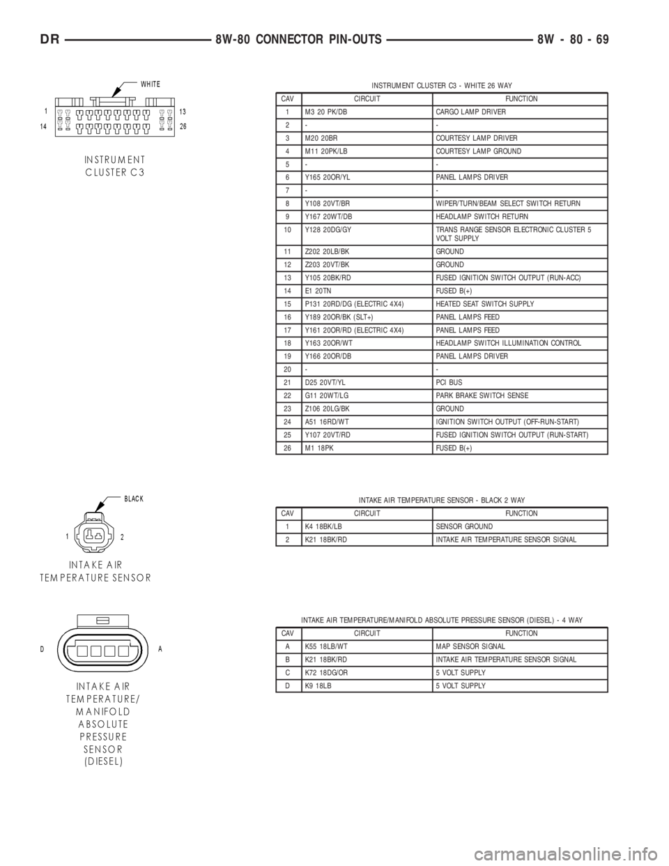
INSTRUMENT CLUSTER C3 - WHITE 26 WAY
CAV CIRCUIT FUNCTION
1 M3 20 PK/DB CARGO LAMP DRIVER
2- -
3 M20 20BR COURTESY LAMP DRIVER
4 M11 20PK/LB COURTESY LAMP GROUND
5- -
6 Y165 20OR/YL PANEL LAMPS DRIVER
7- -
8 Y108 20VT/BR WIPER/TURN/BEAM SELECT SWITCH RETURN
9 Y167 20WT/DB HEADLAMP SWITCH RETURN
10 Y128 20DG/GY TRANS RANGE SENSOR ELECTRONIC CLUSTER 5
VOLT SUPPLY
11 Z202 20LB/BK GROUND
12 Z203 20VT/BK GROUND
13 Y105 20BK/RD FUSED IGNITION SWITCH OUTPUT (RUN-ACC)
14 E1 20TN FUSED B(+)
15 P131 20RD/DG (ELECTRIC 4X4) HEATED SEAT SWITCH SUPPLY
16 Y189 20OR/BK (SLT+) PANEL LAMPS FEED
17 Y161 20OR/RD (ELECTRIC 4X4) PANEL LAMPS FEED
18 Y163 20OR/WT HEADLAMP SWITCH ILLUMINATION CONTROL
19 Y166 20OR/DB PANEL LAMPS DRIVER
20 - -
21 D25 20VT/YL PCI BUS
22 G11 20WT/LG PARK BRAKE SWITCH SENSE
23 Z106 20LG/BK GROUND
24 A51 16RD/WT IGNITION SWITCH OUTPUT (OFF-RUN-START)
25 Y107 20VT/RD FUSED IGNITION SWITCH OUTPUT (RUN-START)
26 M1 18PK FUSED B(+)
INTAKE AIR TEMPERATURE SENSOR - BLACK 2 WAY
CAV CIRCUIT FUNCTION
1 K4 18BK/LB SENSOR GROUND
2 K21 18BK/RD INTAKE AIR TEMPERATURE SENSOR SIGNAL
INTAKE AIR TEMPERATURE/MANIFOLD ABSOLUTE PRESSURE SENSOR (DIESEL)-4WAY
CAV CIRCUIT FUNCTION
A K55 18LB/WT MAP SENSOR SIGNAL
B K21 18BK/RD INTAKE AIR TEMPERATURE SENSOR SIGNAL
C K72 18DG/OR 5 VOLT SUPPLY
D K9 18LB 5 VOLT SUPPLY
DR8W-80 CONNECTOR PIN-OUTS 8W - 80 - 69
Page 1154 of 2895
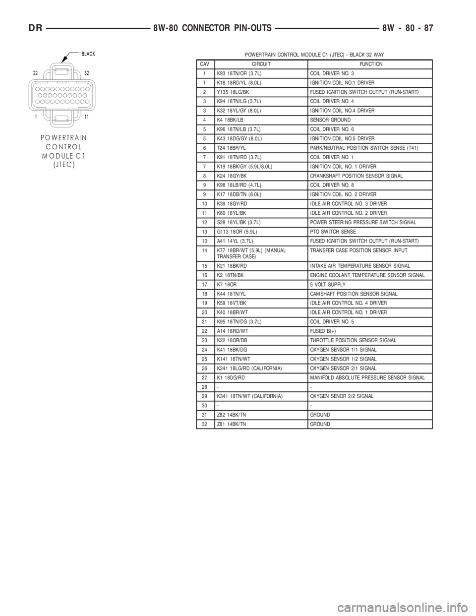
POWERTRAIN CONTROL MODULE C1 (JTEC) - BLACK 32 WAY
CAV CIRCUIT FUNCTION
1 K93 18TN/OR (3.7L) COIL DRIVER NO. 3
1 K18 18RD/YL (8.0L) IGNITION COIL NO.1 DRIVER
2 Y135 18LG/BK FUSED IGNITION SWITCH OUTPUT (RUN-START)
3 K94 18TN/LG (3.7L) COIL DRIVER NO. 4
3 K32 18YL/GY (8.0L) IGNITION COIL NO.4 DRIVER
4 K4 18BK/LB SENSOR GROUND
5 K96 18TN/LB (3.7L) COIL DRIVER NO. 6
5 K43 18DG/GY (8.0L) IGNITION COIL NO.5 DRIVER
6 T24 18BR/YL PARK/NEUTRAL POSITION SWITCH SENSE (T41)
7 K91 18TN/RD (3.7L) COIL DRIVER NO. 1
7 K19 18BK/GY (5.9L/8.0L) IGNITION COIL NO. 1 DRIVER
8 K24 18GY/BK CRANKSHAFT POSITION SENSOR SIGNAL
9 K98 18LB/RD (4.7L) COIL DRIVER NO. 8
9 K17 18DB/TN (8.0L) IGNITION COIL NO. 2 DRIVER
10 K39 18GY/RD IDLE AIR CONTROL NO. 3 DRIVER
11 K60 18YL/BK IDLE AIR CONTROL NO. 2 DRIVER
12 S28 18YL/BK (3.7L) POWER STEERING PRESSURE SWITCH SIGNAL
13 G113 18OR (5.9L) PTO SWITCH SENSE
13 A41 14YL (3.7L) FUSED IGNITION SWITCH OUTPUT (RUN-START)
14 K77 18BR/WT (5.9L) (MANUAL
TRANSFER CASE)TRANSFER CASE POSITION SENSOR INPUT
15 K21 18BK/RD INTAKE AIR TEMPERATURE SENSOR SIGNAL
16 K2 18TN/BK ENGINE COOLANT TEMPERATURE SENSOR SIGNAL
17 K7 18OR 5 VOLT SUPPLY
18 K44 18TN/YL CAMSHAFT POSITION SENSOR SIGNAL
19 K59 18VT/BK IDLE AIR CONTROL NO. 4 DRIVER
20 K40 18BR/WT IDLE AIR CONTROL NO. 1 DRIVER
21 K95 18TN/DG (3.7L) COIL DRIVER NO. 5
22 A14 18RD/WT FUSED B(+)
23 K22 18OR/DB THROTTLE POSITION SENSOR SIGNAL
24 K41 18BK/DG OXYGEN SENSOR 1/1 SIGNAL
25 K141 18TN/WT OXYGEN SENSOR 1/2 SIGNAL
26 K241 18LG/RD (CALIFORNIA) OXYGEN SENSOR 2/1 SIGNAL
27 K1 18DG/RD MANIFOLD ABSOLUTE PRESSURE SENSOR SIGNAL
28 - -
29 K341 18TN/WT (CALIFORNIA) OXYGEN SENOR 2/2 SIGNAL
30 - -
31 Z82 14BK/TN GROUND
32 Z81 14BK/TN GROUND
DR8W-80 CONNECTOR PIN-OUTS 8W - 80 - 87