2003 DODGE RAM Front wheel bearing
[x] Cancel search: Front wheel bearingPage 58 of 2895
DESCRIPTION N´m Ft. Lbs. In. Lbs.
Stabilizer Link
Stabilizer Bar Nut38 27 Ð
Hub/Bearing
Bolts202 149 Ð
Axle Nut 179 Beginning Torque, Then
Rotate 5 to 10 Times With a
Final Torque of 356132 Beginning Torque, Then
Rotate 5 to 10 Times With a
Final Torque of 263Ð
Tie Rod End
Nut75 55 Ð
NOTE: Suspension components with rubber/ure-
thane bushings should be tightened with the vehi-
cle at normal ride height. It is important to have the
springs supporting the weight of the vehicle when
the fasteners are torqued. If springs are not at their
normal ride position, vehicle ride comfort could be
affected and premature bushing wear may occur.
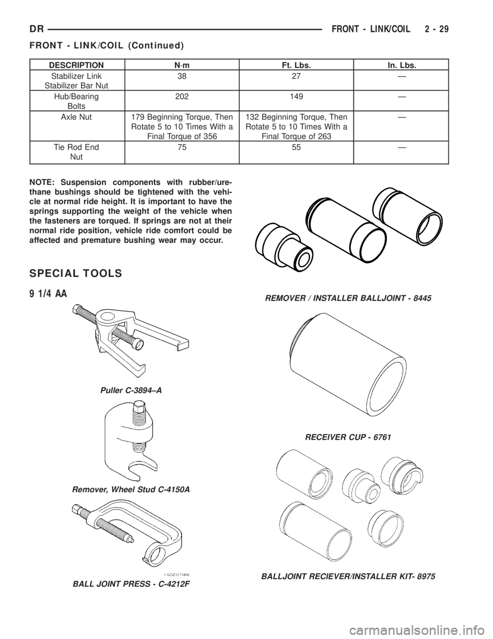
SPECIAL TOOLS
9 1/4 AA
Puller C-3894±A
Remover, Wheel Stud C-4150A
BALL JOINT PRESS - C-4212F
REMOVER / INSTALLER BALLJOINT - 8445
RECEIVER CUP - 6761
BALLJOINT RECIEVER/INSTALLER KIT- 8975
DRFRONT - LINK/COIL 2 - 29
FRONT - LINK/COIL (Continued)
Page 59 of 2895

HUB / BEARING
REMOVAL
(1) Raise and support the vehicle.
(2) Remove the wheel and tire assembly.
(3) Remove the hub extension mounting nuts and
remove the extension from the rotor if equipped (Fig.
1).
(4) Remove the brake caliper, (Refer to 5 -
BRAKES/HYDRAULIC/MECHANICAL/DISC
BRAKE CALIPERS - REMOVAL).
(5) Remove the cotter pin and the hub nut from
the axle shaft (Fig. 2).
(6) Disconnect the ABS wheel speed sensor wire
from under the hood. Remove the sensor wire from
the frame and steering knuckle if equipped.(7) Back off the hub/bearing mounting bolts 1/4
inch each (Fig. 3). Then tap the bolts with a hammer
to loosen the hub/bearing from the steering knuckle.
(8) Remove the hub/bearing mounting bolts and
remove the hub/bearing.
(9) Remove the rotor assembly (Fig. 4), brake
shield and spacer from the steering knuckle.
(10) Press out the wheel studs/hub extension studs
and separate the rotor from the hub (Fig. 5).
(11) Remove the wheel speed sensor (Fig. 6) from
the hub bearing if equipped.
Fig. 1 Hub Extension
1 - HUB EXTENSION
2 - HUB
Fig. 2 Hub Nut Cotter Pin
1 - HUB NUT
2 - COTTER PIN
Fig. 3 Hub/Bearing Mounting Bolts
1 - SOCKET AND EXTENSION
2 - ROTOR AND HUB
3 - STEERING KNUCKLE
Fig. 4 Rotor Hub/Bearing Assembly
1 - ROTOR AND HUB
2 - UNIT BEARING ASSEMBLY
3 - SEAL
2 - 30 FRONT - LINK/COILDR
Page 60 of 2895

INSTALLATION
(1) Install the wheel speed sensor in the hub bear-
ing if equipped.
(2) Position the rotor on the hub/bearing.
(3) Press the wheel studs/hub extension studs
through the back side of the rotor and through the
hub bearing flange (Fig. 7).
(4) Apply a liberal quantity of anti-seize compound
to the splines of the front drive shaft.
(5) Insert the two rearmost, top and bottom rotor
hub bolts in the steering knuckle. Insert the bolts
through the back side of the knuckle so they extend
out the front face as shown.
(6) Position the hub spacer (Fig. 8) and brake
shield (Fig. 9) on bolts just installed in knuckle.NOTE: If the vehicle is equipped with a wheel speed
sensor the brake shield must be positioned on the
hub bearing (Fig. 10).
(7) Align the rotor hub with the drive shaft and
start the shaft into the rotor hub splines.
NOTE: Position wheel speed sensor wire at the top
of the knuckle if equipped.
Fig. 5 ROTOR AND HUB/BEARING
1 - HUB BEARING
2 - ROTOR
Fig. 6 Wheel Speed Sensor
1 - HUB BEARING
2 - WHEEL SPEED SENSOR
Fig. 7 Rotor, Hub/Bearing And Stud
1 - HUB BEARING
2 - ROTOR
3 - STUD
Fig. 8 Hub Spacer
1 - ROTOR HUB BOLTS
2 - HUB SPACER (POSITION FLAT TO REAR)
3 - APPLY ANTI-SEIZE COMPOUND TO SPLINES
DRFRONT - LINK/COIL 2 - 31
HUB / BEARING (Continued)
Page 61 of 2895

(8) Align the bolt holes in the hub bearing flange
with the bolts installed in the knuckle. Then thread
the bolts into the bearing flange far enough to hold
the assembly in place.(9) Install the remaining bolts. Tighten the hub/
bearing bolts to 202 N´m (149 ft. lbs.
(10) Install the washer and axle nut and tighten a
beginning torque of 179 N´m (132 ft. lbs.).
(11) Rotate the axle 5 to 10 times to seat the hub
bearing.
(12) Tighten to a final torque of 356 N´m (263 ft.
lbs.).
(13) Align the axle nut to the next forward cotter
pin hole and install a new cotter pin in the axle nut.
(14) Install the brake caliper, (Refer to 5 -
BRAKES/HYDRAULIC/MECHANICAL/DISC
BRAKE CALIPERS - INSTALLATION).
(15) Install the sensor wire to the steering knuckle
and frame and if equipped. Connect the wheel speed
sensor wire under the hood.
(16) Install the wheel and tire assemblies, (Refer
to 22 - TIRES/WHEELS/WHEELS - STANDARD
PROCEDURE).
(17) Remove the support and lower the vehicle.
(18) Apply the brakes several times to seat the
brake shoes and caliper piston. Do not move the vehi-
cle until a firm brake pedal is obtained.
LOWER BALL JOINT
REMOVAL
(1) Remove lower snap ring from the lower ball
joint (Fig. 11).
(2) Position special tool 8975±2 (RECEIVER) and
8975±4 (DRIVER) with tool C4212±F as shown to
remove lower ball stud (Fig. 12).
Fig. 9 Brake Shield
1 - BRAKE SHIELD
2 - HUB BEARING BOLTS
3 - STEERING KNUCKLE
Fig. 10 Brake Shield With Wheel Speed Sensor
1 - WHEEL SPEED SENSOR
2 - HUB BEARING
3 - SHIELD
Fig. 11 LOWER SNAP RING
2 - 32 FRONT - LINK/COILDR
HUB / BEARING (Continued)
Page 74 of 2895
DIFFERENTIAL & DRIVELINE
TABLE OF CONTENTS
page page
PROPELLER SHAFT......................1
HALF SHAFT...........................11
FRONT AXLE - C205F....................18
FRONT AXLE - 9 1/4 AA...................45REAR AXLE-91/4.......................69
REAR AXLE - 10 1/2 AA..................100
REAR AXLE - 11 1/2 AA..................127
PROPELLER SHAFT
TABLE OF CONTENTS
page page
PROPELLER SHAFT
DIAGNOSIS AND TESTING................1
STANDARD PROCEDURE.................3
SPECIFICATIONS........................6
SPECIAL TOOLS........................6
FRONT PROPELLER SHAFT
REMOVAL.............................6
INSTALLATION..........................7
REAR PROPELLER SHAFT
REMOVAL.............................7INSTALLATION..........................8
CENTER BEARING
REMOVAL.............................8
INSTALLATION..........................8
ADJUSTMENTS.........................8
SINGLE CARDAN UNIVERSAL JOINTS
DISASSEMBLY..........................9
ASSEMBLY.............................9
PROPELLER SHAFT
DIAGNOSIS AND TESTING
PROPELLER SHAFT VIBRATION
Tires that are out-of-round or wheels that are
unbalanced, will cause a low frequency vibration.
Brake drums that are unbalanced will cause a
harsh, low frequency vibration.Driveline vibration can also result from loose or
damaged engine mounts.
Propeller shaft vibration increases as the vehicle
speed is increased. A vibration that occurs within a
specific speed range is not usually caused by a pro-
peller shaft being unbalanced. Defective universal
joints or an incorrect propeller shaft angle are usu-
ally the cause of such a vibration.
DRDIFFERENTIAL & DRIVELINE 3 - 1
Page 76 of 2895
(15) If the vibration remains unacceptable, apply
the same steps to the front end of the propeller shaft.
(16) Install the wheel and tires. Lower the vehicle.
PROPELLER SHAFT RUNOUT
(1) Remove dirt, rust, paint and undercoating from
the propeller shaft surface where the dial indicator
will contact the shaft.
(2) The dial indicator must be installed perpendic-
ular to the shaft surface.
(3) Measure runout at the center and ends of the
shaft sufficiently far away from weld areas to ensure
that the effects of the weld process will not enter into
the measurements.
(4) Refer to Runout Specifications chart.
(5) If the propeller shaft runout is out of specifica-
tion, remove the propeller shaft, index the shaft 180É,
and re-install the propeller shaft. Measure shaft
runout again.
(6) If the propeller shaft runout is now within
specifications, mark the shaft and yokes for proper
orientation.
(7) If the propeller shaft runout is not within spec-
ifications, verify that the runout of the transmission/
transfer case and axle are within specifications.
Correct as necessary and re-measure propeller shaft
runout.
(8) Replace the propeller shaft if the runout still
exceeds the limits.
RUNOUT SPECIFICATIONS
Front of Shaft 0.020 in. (0.50 mm)
Center of Shaft 0.025 in. (0.63 mm)
Rear of Shaft 0.020 in. (0.50 mm)
note:
Measure front/rear runout approximately 3 inches (76
mm) from the weld seam at each end of the shaft
tube for tube lengths over 30 inches. For tube lengths
under 30 inches, the maximum allowed runout is
0.020 in. (0.50 mm) for the full length of the tube.
STANDARD PROCEDURE
PROPELLER SHAFT ANGLE
This procedure applies to both the front/rear pro-
peller shafts. To obtain the front output angle (A) on
the front propeller shaft, place the inclinometer the
machined surface of the C/V joint.
(1) To check driveline alignment, raise and support
the vehicle at the axles as level as possible. Allow the
wheels and propeller shaft to turn.
(2) Remove any external bearing snap rings, if
equipped from universal joint so protractor base sits
flat.
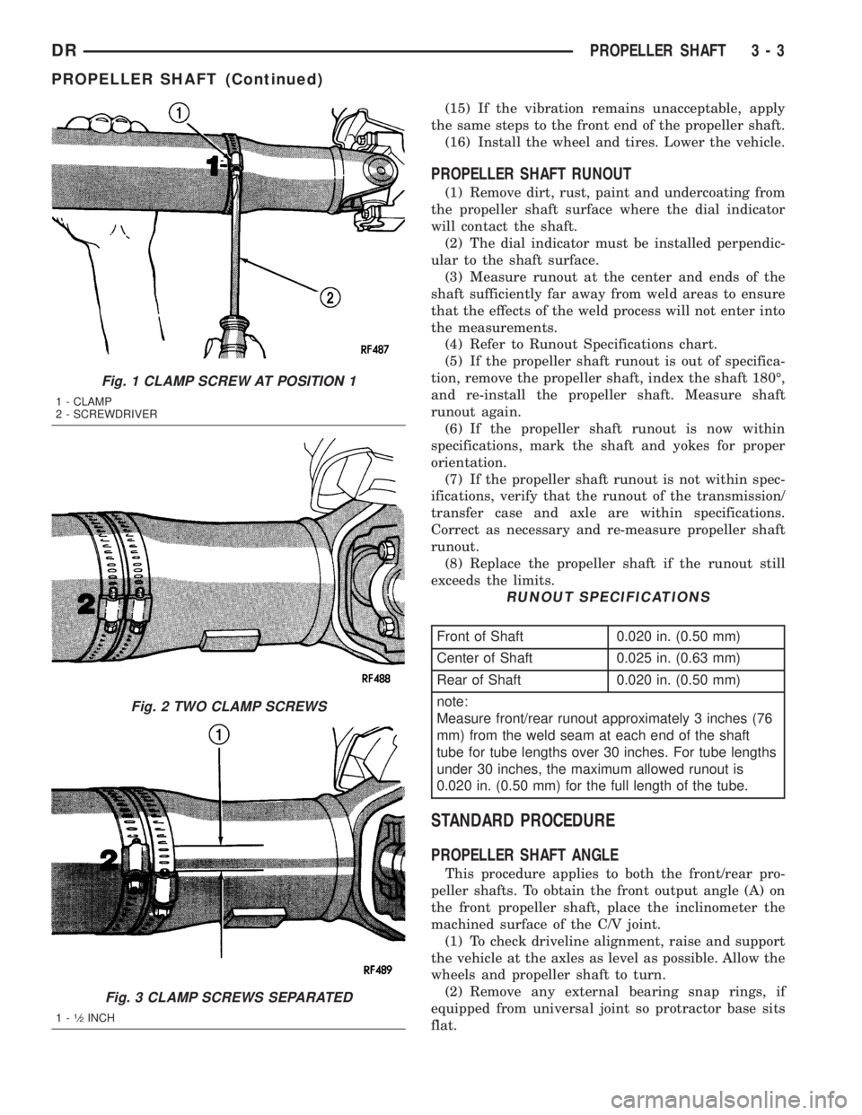
Fig. 1 CLAMP SCREW AT POSITION 1
1 - CLAMP
2 - SCREWDRIVER
Fig. 2 TWO CLAMP SCREWS
Fig. 3 CLAMP SCREWS SEPARATED
1-1¤2INCH
DRPROPELLER SHAFT 3 - 3
PROPELLER SHAFT (Continued)
Page 85 of 2895

(9) Disengage inner C/V joint from the axle shaft
snap-ring by apply pressure with two pry bars
between the C/V housing and axle housing.
(10) Tilt the knuckle out and push the half shaft
out of the knuckle (Fig. 2).
CAUTION: Do not damage outer C/V threads while
removing half shaft.
(11) Remove the half shaft from the vehicle.
INSTALLATION
(1) Clean hub bearing bore, hub bearing mating
surface and half shaft splines.(2) Apply a light coating of grease to the front axle
shaft output splines.
(3) Install half shaft into the knuckle (Fig. 3).
(4) Install half shaft on the axle output shaft.
Push firmly to engage the axle output shaft snap
ring into the inner C/V housing.
(5) Install upper ball joint into the knuckle.
(6) Install upper ball joint nut and tighten to spec-
ification.
(7) Install lower shock absorber bolt and tighten to
specification.
(8) Install brake rotor and caliper.
(9) Install half shaft hub nut and tighten to 251
N´m (185 ft. lbs.).
(10) Install the wheel and tire assembly.
SPECIFICATIONS
TORQUE SPECIFICATIONS
DESCRIPTION N´m Ft. Lbs. In. Lbs.
Half Shaft Nut 251 185 -
SPECIAL TOOLS
Fig. 2 STEERING KNUCKLE
1 - STEERING KNUCKLE
2 - SHOCK
3 - HALFSHAFT
4 - DISC BRAKE CALIPER
5 - HUB/BEARING
Fig. 3 HALF SHAFT AND HUB/BEARING
1 - HUB/BEARING MOUNTING NUTS
2 - HALF SHAFT
CLAMP INSTALLER C-4975A
3 - 12 HALF SHAFTDR
HALF SHAFT (Continued)
Page 91 of 2895
FRONT AXLE - C205F
TABLE OF CONTENTS
page page
FRONT AXLE - C205F
DESCRIPTION.........................18
OPERATION...........................18
DIAGNOSIS AND TESTING................18
REMOVAL.............................21
INSTALLATION.........................21
ADJUSTMENTS........................21
SPECIFICATIONS.......................29
SPECIAL TOOLS.......................30
AXLE SHAFTS
REMOVAL.............................33
INSTALLATION.........................33
AXLE SHAFT SEALS
REMOVAL.............................33
INSTALLATION.........................33
AXLE BEARINGS
REMOVAL.............................33INSTALLATION.........................34
PINION SEAL
REMOVAL.............................34
INSTALLATION.........................35
DIFFERENTIAL
DESCRIPTION.........................36
OPERATION...........................36
REMOVAL.............................36
DISASSEMBLY.........................37
ASSEMBLY............................38
INSTALLATION.........................38
DIFFERENTIAL CASE BEARINGS
REMOVAL.............................39
INSTALLATION.........................39
PINION GEAR/RING GEAR
REMOVAL.............................40
INSTALLATION.........................42
FRONT AXLE - C205F
DESCRIPTION
The axle consists of an alumunum center section
with an axle tube extending from one side. The tube
is pressed into the differential housing. The power is
transferred from the axle through two constant veloc-
ity (C/V) drive shafts to the wheel hubs. The drive
shafts are identical and interchangeable.
OPERATION
The axle receives power from the propeller shaft.
The propeller shaft is connected to the pinion gear
which rotates the differential through the gear mesh
with the ring gear bolted to the differential case. The
engine power is transmitted to the axle shafts
through the pinion mate and side gears. The side
gears are splined to the axle shafts.
DIAGNOSIS AND TESTING
GEAR NOISE
Axle gear noise can be caused by insufficient lubri-
cant, incorrect backlash, tooth contact, worn/damaged
gears or the carrier housing not having the proper
offset and squareness.
Gear noise usually happens at a specific speed
range. The noise can also occur during a specific type
of driving condition. These conditions are accelera-
tion, deceleration, coast, or constant load.When road testing, first warm-up the axle fluid by
driving the vehicle at least 5 miles and then acceler-
ate the vehicle to the speed range where the noise is
the greatest. Shift out-of-gear and coast through the
peak-noise range. If the noise stops or changes
greatly:
²Check for insufficient lubricant.
²Incorrect ring gear backlash.
²Gear damage.
Differential side gears and pinions can be checked
by turning the vehicle. They usually do not cause
noise during straight-ahead driving when the gears
are unloaded. The side gears are loaded during vehi-
cle turns. A worn pinion mate shaft can also cause a
snapping or a knocking noise.
BEARING NOISE
The axle shaft, differential and pinion bearings can
all produce noise when worn or damaged. Bearing
noise can be either a whining, or a growling sound.
Pinion bearings have a constant-pitch noise. This
noise changes only with vehicle speed. Pinion bearing
noise will be higher pitched because it rotates at a
faster rate. Drive the vehicle and load the differen-
tial. If bearing noise occurs, the rear pinion bearing
is the source of the noise. If the bearing noise is
heard during a coast, the front pinion bearing is the
source.
Worn or damaged differential bearings usually pro-
duce a low pitch noise. Differential bearing noise is
similar to pinion bearing noise. The pitch of differen-
3 - 18 FRONT AXLE - C205FDR