Page 131 of 1184
YesNo
1
Perform an Euro On-Board Diagnostic (EOBD)
System Check.
Is the check complete.
–
Go to Step")
ENGINE CONTROLS 1F–33
DAEWOO M-150 BL2
Malfunction Indicator Lamp On Steady
StepActionValue(s)YesNo
1
Perform an Euro On-Board Diagnostic (EOBD)
System Check.
Is the check complete.
–
Go to Step 2
Go to “Euro
On-Board
Diagnostic
System Check”
2
1. Turn the ignition OFF.
2. Install the scan tool.
3. Command the Malfunction Indicator Lamp (MIL)
on and off.
Does the MIL turn on and off when commanded?
–
Go to Step 7Go to Step 3
3
1. Turn the ignition OFF.
2. Disconnect the engine control module (ECM)
connector.
3. Turn the ignition ON.
Is the MIL off?
–
Go to Step 6Go to Step 4
4
Check the MIL control circuit for a short to ground
and repair as needed.
Is a repair necessary?
–
Go to Step 7Go to Step 5
5
Replace the instrument panel cluster. Refer to
Section 9E, Instrumentation/Driver Information.
Is the repair complete?
–
Go to Step 7
–
6Replace the ECM.
Is the repair complete?–Go to Step 7–
7
1. Using the scan tool, clear the Diagnostic Trouble
Codes(DTCs).
2. Attempt to start the engine.
Does the engine start and continue to run?
–
Go to Step 8Go to Step 1
8
Allow the engine to idle until normal operating
temperature is reached.
Check if any DTCs are set.
Are any DTCs displayed that have not been
diagnosed?
–
Go to applicable
DTC table
System OK
Page 150 of 1184
 is the Data Link Connector (")
1F–52 ENGINE CONTROLS
DAEWOO M-150 BL2
MAA1F010
DATA LINK CONNECTOR DIAGNOSIS
Circuit Description
The provision for communicating with the Engine Con-
trol Module (ECM) is the Data Link Connector (DLC). It
is located under the instrument panel. The DLC is used
to connect the scan tool. Battery power and ground is
supplied for the scan tool through the DLC. The Key-
word 2000 serial data circuit to the DLC allows the ECM
to communicate with the scan tool. A Universal Asyn-
chronous Receiver Transmitter (UART) serial data line
is used to communicate with the other modules such as
the Electronic Brake Control Module (EBCM), the Sup-
plemental Inflatable Restraint (SIR) system. and the In-
strument Panel Cluster.
Diagnostic Aids
Ensure that the correct application (model line, car year,
etc.) has been selected on the scan tool. If communica-
tion still cannot be established, try the scan tool onanother vehicle to ensure that the scan tool or cables
are not the cause of the condition.
An intermittent may be caused by a poor connection,
rubbed through wire insulation, or a broken wire inside
the insulation.
Any circuitry that is suspected of causing an intermittent
complaint should be thoroughly checked for the follow-
ing conditions:
�Backed-out terminals.
�Improper mating of terminals.
�Broken locks.
�Improperly formed or damaged terminals.
�Poor terminal-to-wiring connection.
�Physical damage to the wiring harness.
�Corrosion.
Page 508 of 1184
4A – 2 HYDRAULIC BRAKES
DAEWOO M-150 BL2
DESCRIPTION AND OPERATION
WARNING LAMP OPERATION
This brake system uses a BRAKE warning lamp located
in the instrument panel cluster. When the ignition switch
is in the III position, the BRAKE warning lamp should il-
luminate. It should go off when the ignition switch return
to II position. The following conditions will activate the
BRAKE warning lamp.
�The lamp should be on whenever the parking brake
applied and the ignition switch is in the II position.
�A low fluid level in the master cylinder will turn the
BRAKE warning lamp on.
D17A007A
Page 511 of 1184

HYDRAULIC BRAKES 4A–5
DAEWOO M-150 BL2
WARNING LAMP OPERATION
This brake system uses a BRAKE warning lamp located
in the instrument panel cluster. When the ignition switch
is in the III position, the BRAKE warning lamp should
glow and then go OFF when the ignition switch returns
to the II position.The following conditions will activate the BRAKE lamp:
�Parking brake applied. The light should be on when-
ever the parking brake is applied and the ignition
switch is II.
�Low fluid level. A low fluid level in the master cylinder
will turn the BRAKE lamp ON.
BRAKE SYSTEM FAULT
���������� ����������Condition������������� �������������Probable cause�������������� ��������������Correction
Brake Warning Lamp ON�Brake fluid leaks.�Repair the leaks or add th fluid.
�Parking brake switch shorted to
ground.�Repair the short ground.
�Faulty the fluid level sensor.�Replace the sensor.
Stoplamp ON�Faulty the stoplamp switch.�Replace the stoplamp switch.
�Push rod length is short.�Adjust the push rod length of the
power booster.
�Stoplamp switch circuit shorted to
battery.�Repair or Replace the wiring harness.
Poor Braking�Brake fluid lacks or leaks.�Repair the leaks or add the fluid.
�Brake fluid contamination.�Replace the fluid.
�Air in the brake system.�Bleed the brake system.
�Damaged brake lines.�Replace the brake lines.
�Damaged vacuum hose or faulty
check valve.�Replace the vacuum hose or check
value.
Dragging Brake�No free play at the brake pedal.�Adjust the free play.
�Weakened the brake pedal return
spring.�Replace the return spring.
�Faulty master cylinder.�Replace the master cylinder.
�Air in the brake system.�Bleed the brake system.
Pedal Over Stroke�Brake fluid lacks or leaks.�Repair the leaks or add the fluid.
�Poor adjustment of the brake pedal
free play.�Adjust the push rod length of the
power booster.
Page 618 of 1184
4G – 2 PARKING BRAKE
DAEWOO M-150 BL2
DESCRIPTION AND OPERATION
PARKING BRAKE
This braking system uses a BRAKE warning light lo-
cated in the instrument panel cluster. When the ignition
switch is in the III position, the BRAKE warning light
should glow and go OFF when the parking brake lever is
released. Whenever the parking brake is applied and theignition switch is II, the BRAKE warning light should
glow.
When the brake is firmly applied, the parking brake
should securely hold the vehicle with ample pedal travel
remaining. Check for frayed cables, rust, etc., or any
condition that may inhibit present (or future) free move-
ment of the parking brake lever assembly.
Page 645 of 1184

5B–20 FIVE-SPEED MANUAL TRANSAXLE
DAEWOO M-150 BL2
D103B534
2. Remove the battery. Refer to Section 1E, Engine
Electrical.
3. Disconnect the instrument cluster side cable. Refer to
Section 9E, Instrumentation/Driver Information.
4. Remove the speedometer cable.
�Remove the cable grommet (1).
�Pull out the speedometer cable from the dash pan-
el.
D103B535
Inspection Procedure
1. Remove the O–ring from the speedometer driven
gear housing.
2. Remove the driven gear pin and disconnect the driv-
en gear.
�Check for a damaged or torn O–ring.
�Check for a worn or damaged tooth of driven gear.
a. O–ring.
b. Driven gear pin.
c. Driven gear.
D103B536
Installation Procedure
1. Install in the reverse order of removal.
Important: Install the speedometer driven gear assem-
bly after connecting the speedometer cable with the
speedometer driven gear assembly completely.
D13B537A
2. Install the speedometer driven gear assembly to
transaxle housing.
Tighten
Tighten the speedometer driven gear assembly bolt
to 4–7 N�m (35–62 lb-in).
Page 768 of 1184
7A – 18 HEATING AND VENTILATION SYSTEM
DAEWOO M-150 BL2
REPAIR INSTRUCTIONS
ON-VEHICLE SERVICE
D108A502
D108A501
CONTROL ASSEMBLY AND
CONTROL CABLES
(Left–Hand Drive Shown, Right–Hand
Drive Similar)
Removal Procedure
1. Disconnect the negative battery cable.
2. Remove the instrument cluster housing trim panel.
Refer to Section 9E, Instrumentation/Driver informa-
tion.
3. Remove the control assembly.
�Remove the control assembly retaining screws (1).
�Separate the control assembly from the instrument
panel (2).
�Disconnect the electrical connectors (3).
�Disconnect the mode control cable from the heater
module (4).
�Disconnect the temperature control cable from the
heater module (5).
�Remove the glove box from the instrument panel.
Refer to Section 9E, Instrumentation/Driver Infor-
mation.
D108A503
�Disconnect the recirculating/fresh air door cable
from the blower module (6).
Page 769 of 1184
HEATING AND VENTILATION SYSTEM 7A–19
DAEWOO M-150 BL2
D108A504
D108A505
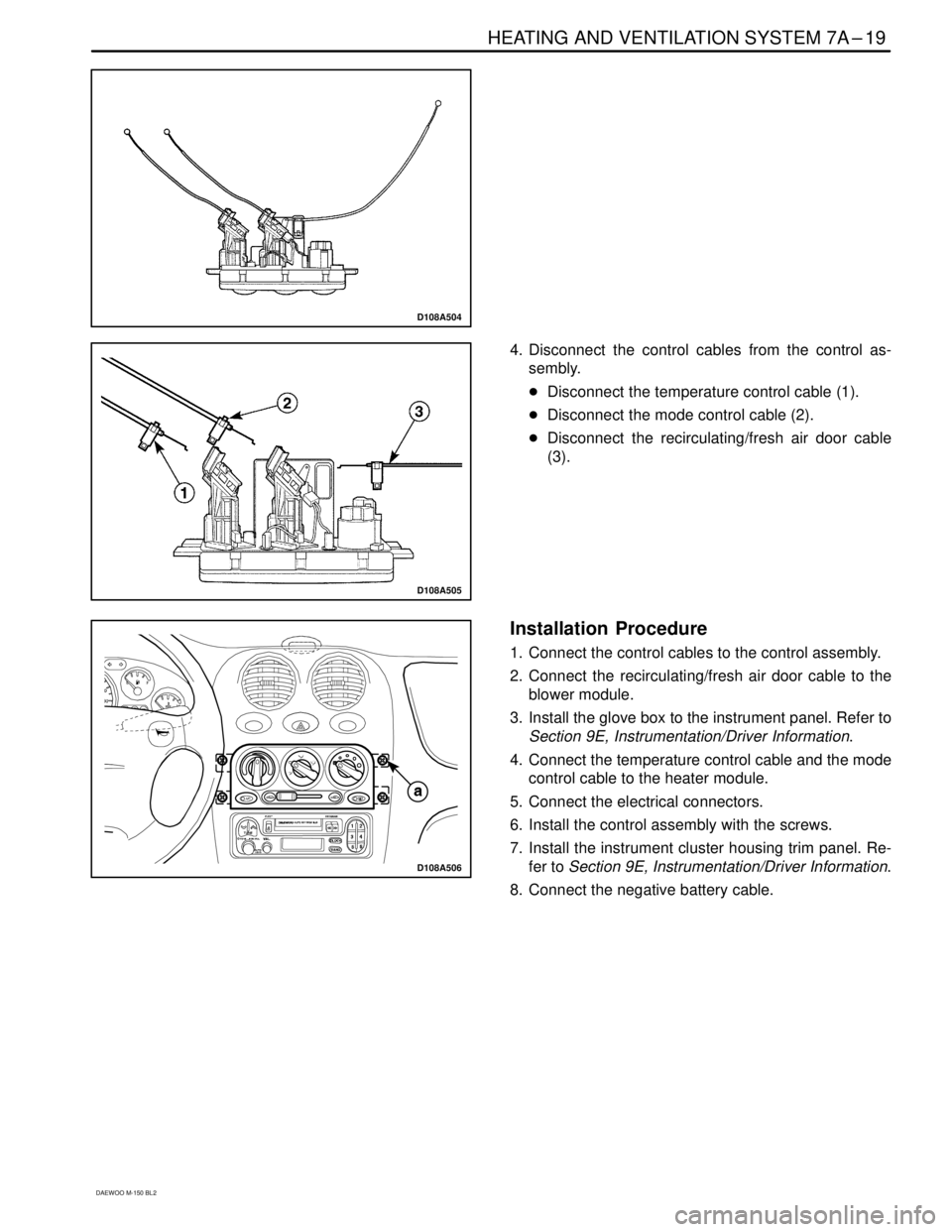
4. Disconnect the control cables from the control as-
sembly.
�Disconnect the temperature control cable (1).
�Disconnect the mode control cable (2).
�Disconnect the recirculating/fresh air door cable
(3).
D108A506
Installation Procedure
1. Connect the control cables to the control assembly.
2. Connect the recirculating/fresh air door cable to the
blower module.
3. Install the glove box to the instrument panel. Refer to
Section 9E, Instrumentation/Driver Information.
4. Connect the temperature control cable and the mode
control cable to the heater module.
5. Connect the electrical connectors.
6. Install the control assembly with the screws.
7. Install the instrument cluster housing trim panel. Re-
fer to Section 9E, Instrumentation/Driver Information.
8. Connect the negative battery cable.