Page 718 of 1184
6D – 2 MANUAL STEERING GEAR
DAEWOO M-150 BL2
DESCRIPTION AND OPERATION
MANUAL RACK AND PINION
The manual rack and pinion steering system consists of
two main components: the rack and the pinion. The mo-
tion of the pinion is transferred through the pinion teeth
that mesh with the teeth on the rack, which moves the
rack. The force is then transmitted through the arms on
the struts, which turn the wheels.
Page 719 of 1184
MANUAL STEERING GEAR 6D–3
DAEWOO M-150 BL2
COMPONENT LOCATOR
MANUAL RACK AND PINION STEERING GEAR
(Left–Hand Drive Shown, Right–Hand Drive Similar)
D105B401
1. Manual Steering Gear
2. Steering Gear Bracket
3. Cotter Pin
4. Castellated Nut
5. Tie Rod End
6. Tie Rod End Lock Nut
7. Rack and Pinion Boot Clamp
8. Rack and Pinion Boot
9. Rack and Pinion Boot Wire Clamp
10. Tie Rod
11. Shock Damper Ring
12. Steering Rack Gear13. Bulkhead Retainer
14. Bulkhead Bushing
15. Steering Gear Housing
16. Steering Gear Bracket Bushing
17. Packing
18. Dust Cover
19. Pinion Plug
20. Steering Pinion Gear
21. Roller Bearing
22. Rack Bearing
23. Adjuster Spring
24. Adjuster Plug
Page 720 of 1184
6D –4 MANUAL STEERING GEAR
DAEWOO M-150 BL2
DIAGNOSTIC INFORMATION AND PROCEDURES
MANUAL RACK AND PINION STEERING GEAR
ConditionProbable CauseCorrection
Excessive Play or�Poor adjustment of steering gear.�Perform straight–ahead check.
Looseness in the
Steering System�Improperly installed tie rods.�Tighten the tie rods.
�Improper and insufficient lubrication.�Lubricate the rack and pinion
assembly.
Rattling Noise in the
Steering Gear
�Improperly installed steering gear mounting.�Tighten the steering gear mounting
bolts.
�Improperly installed tie rods.�Tighten the tie rods.
Page 721 of 1184

MANUAL STEERING GEAR 6D–5
DAEWOO M-150 BL2
STRAIGHT-AHEAD CHECK
After all the necessary operations on the steering gear
are completed, check the exact straight-ahead position
of the steering in each case.
With the vehicle on the floor, place the steering wheel in
the straight-ahead position. Mark the centerline of both
tires on the floor. Turn the steering wheel all the way to
the right and mark the new centerline of both tires on the
floor.
������� �������Application������ ������Tire������ ������Specified Valve
������� ������������� ������145, 15537.5 – 41.5�
������� �������Inside Angle������ ������17532.9 – 36.9�
������� ������������� ������145, 15531.5 – 35.5�
������� �������Outside Angle������ ������17528.5 – 32.5�
D105B301
Front Outside Angle
Inside Angle
Straight Ahead Check Table
���� ����Step����������������� �����������������Action����� �����Value(s)������� �������Yes������ ������No
���� �
��� �
��� ����
1
����������������� �
���������������� �
���������������� �����������������
Place the steering wheel in the straight-ahead posi-
tion.
Is the wheel in the correct position?����� �
���� �
���� �����
–
������� �
������ �
������ �������Go to Step 2
������ �
����� �
����� ������
–
���� �
��� ����
2����������������� �
���������������� �����������������
Is the steering wheel off center by more than 5 de-
grees?����� �
���� �����–������� �
������ �������Go to Step 4������ �
����� ������Go to Step 5
���� �
��� ����3����������������� �
���������������� �����������������
The pinion is displaced on the rack. The steering
pinion position must be corrected.
Is the repair complete?����� �
���� �����–������� �
������ �������Go to Step 2
������ �
����� ������–
���� �
��� �
��� ����
4
����������������� �
���������������� �
���������������� �����������������
Remove steering wheel and center on the spindle
splines.
Is the repair complete?����� �
���� �
���� �����
–
������� �
������ �
������ �������Go to Step 2
������ �
����� �
����� ������
–
���� �
��� �
��� ����
5
����������������� �
���������������� �
���������������� �����������������
Turn the steering wheel all the way to the right. Mea-
sure the inner and the outer angles of the tire cent-
erline compared to the straight-ahead centerline. Do
the angles match the value specified?����� �
���� �
���� �����
Refer to
“Straight–
Ahead Check”
in this section������� �
������ �
������ �������System OK
������ �
����� �
����� ������Go to Step 6���� �
��� �
��� ����
6
����������������� �
���������������� �
���������������� �����������������
The rack assembly was not assembled correctly.
Repair as needed.
Is the repair complete?����� �
���� �
���� �����
–
������� �
������ �
������ �������Go to Step 5
������ �
����� �
����� ������
–
Page 722 of 1184

6D –6 MANUAL STEERING GEAR
DAEWOO M-150 BL2
STEERING WHEEL RESTORATION
1. Turn the steering wheel fast to the right and left and
turn it slowly as the same way.
2. Check if the steering wheel restoration for the wheel
turning to right and the one to the left are same.
3. Turn the steering wheel to 90� about 1–2 seconds
and loosen the steering wheel during the low speed
driving.
4. If the steering wheel restores above 70%, the steer-
ing wheel restoration is OK.
5. If the restoration is poor, check the tire pressure,
steering gear preload, and steering gear operation.
And repair the fault.
CHECK THE TURNING RESISTANCE
OF THE TIE ROD END OR TIE ROD
1. Turn the ball joint of the tie rod end or the tie rod about
10 times.
2. Use a spring balance to check the turning resistance
of each ball joint.
D105B302
���������� ����������Application�������� ��������Specified Value���������� �
��������� ����������Tie Rod End Ball Joint0.49 – 3.43 N�m
(4.5 – 30 lb-in.)
���������� �
��������� ����������Tie Rod Ball Joint0.49 – 3.43 N�m
(4.5 – 30 lb-in.)
3. If the values exceed the specified values, replace the
tie rod end or the tie rod.
4. But, If the ball joint of the tie rod end or the tie rod falls
down of itself, replace it.
ADJUST THE FREE LOAD OF THE
STEERING GEAR
1. Place the steering wheel in the straight–ahead posi-
tion.
2. Raise and suitably support the vehicle.
3. Check the torque of the adjuster plug.
4 When the measured torque is below the specification
value or the measured torque is over the specification
value, adjust the tightening torque.
�Place the rack gear in the straight–ahead position.
�Tighten the adjust plug to 95 N�m (70 lb-ft).
�Turn the steering wheel all the way to the right and
the left about 5 times repeatedly.
�Place the rack gear in the straight–ahead position.
�Loosen the adjust plug.
�Tighten the adjust plug to 8 N�m (71 lb-in.).
�Set the torque in the 0.8–1.3 N�m (8–12 lb-in.) by
loosening the adjust plug to 0� − 90�.
D105B303
Page 723 of 1184
MANUAL STEERING GEAR 6D–7
DAEWOO M-150 BL2
REPAIR INSTRUCTIONS
ON–VEHICLE SERVICE
D105B501
TIE ROD END
Tools Required
KM–507–B Ball Joint Remover
Removal Procedure
1. Remove the wheel. Refer to Section 2E, Tires and
wheels.
2. Disconnect the tie rod and from the steering knuckle.
�Remove the cotter pin (1).
�Remove the castellated nut (2).
�Use a ball joint remover KM–507–B, separate the
tie rod end (3).
D105B502
3. Remove the tie rod end.
�Mark the tie rod, tie rod end lock nut and tie rod end
(1).
�Loosen the tie rod end lock nut anticlockwise (2).
�Loosen the tie rod end (3).
D105B503
Page 724 of 1184
6D –8 MANUAL STEERING GEAR
DAEWOO M-150 BL2
D15B504B
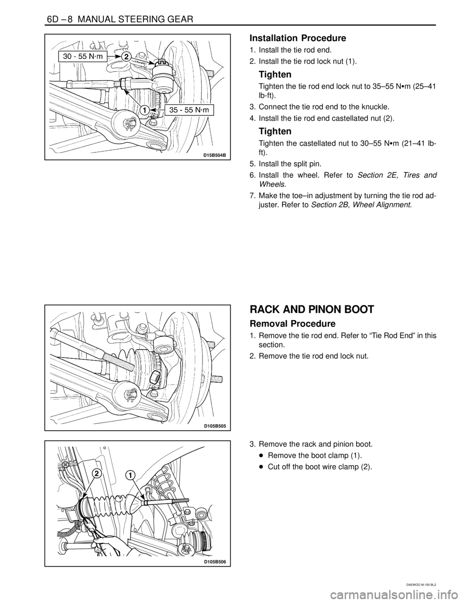
Installation Procedure
1. Install the tie rod end.
2. Install the tie rod lock nut (1).
Tighten
Tighten the tie rod end lock nut to 35–55 N�m (25–41
lb-ft).
3. Connect the tie rod end to the knuckle.
4. Install the tie rod end castellated nut (2).
Tighten
Tighten the castellated nut to 30–55 N�m (21–41 lb-
ft).
5. Install the split pin.
6. Install the wheel. Refer to Section 2E, Tires and
Wheels.
7. Make the toe–in adjustment by turning the tie rod ad-
juster. Refer to Section 2B, Wheel Alignment.
D105B505
RACK AND PINON BOOT
Removal Procedure
1. Remove the tie rod end. Refer to “Tie Rod End” in this
section.
2. Remove the tie rod end lock nut.
D105B506
3. Remove the rack and pinion boot.
�Remove the boot clamp (1).
�Cut off the boot wire clamp (2).
Page 725 of 1184
.
�Remove the boot (4).
D105B508
Installation Procedure
1. Install the rack and pinion boot")
MANUAL STEERING GEAR 6D–9
DAEWOO M-150 BL2
D105B507
�Coat the greases on the tie rod to ease removal
(3).
�Remove the boot (4).
D105B508
Installation Procedure
1. Install the rack and pinion boot with the clamp and the
wire clamp.
2. Install the tie rod end nut.
3. Install the tie rod end. Refer to “Tie Rod End” in this
section.
D105B509
D105B510
RACK AND PINION STEERING GEAR
ASSEMBLY
(Left–Hand Drive Shown, Right–Hand
Drive Similar)
Removal Procedure
1. Remove the intermediate shaft lower pinch bolt. Re-
fer to Section 6E, Steering Wheel and Column.
2. Remove the wheels. Refer to Section 2E, Tires and
Wheels.
3. Disconnect the tie rod end from the steering knuckle.
Refer to “Tie Rod End” in this section.
4. Remove the front exhaust pipe nuts. Refer to Section
1G, Engine Exhaust.
5. Remove the steering gear assembly from the vehicle.
�Remove the steering gear bracket bolts (1).
�Remove the steering gear bracket (2).
�Remove the steering gear assembly.
�Remove the packing (3).


D105B401
1. Manual Steering Gear
2. Steering")