Page 425 of 1184
ENGINE EXHAUST 1G–3
DAEWOO M-150 BL2
COMPONENT LOCATOR
EXHAUST SYSTEM
D12G4011
1 Pup-up Catalytic Converter
2 Front Exhaust Pipe/Catalytic Converter
Assembly3 Front Muffler Pipe
4 Rear Muffler Pipe
Page 426 of 1184
1G–4 ENGINE EXHAUST
DAEWOO M-150 BL2
REPAIR INSTRUCTIONS
ON–VEHICLE SERVICE
MAA1G010
EXHAUST PIPE/CATALYTIC
CONVERTER
Caution : Make sure to confirm that the components
is cool. And do work.
Removal Procedure
1. Remove the floor console. Refer to Section 9G, Inte-
rior Trim, if equipped Heated Oxygen Sensor (HO2S).
2. Disconnect HO2S connector.
D102G501
3. Remove the front exhaust pipe from the exhaust
manifold or pup-up catalytic converter.
�Remove the nuts (1).
�Remove the gasket (2).
4. Check the gasket for damage or crack.
D102G502
5. Remove the front exhaust pipe from the front muffler
pipe.
�Remove the nuts (1).
Page 427 of 1184

ENGINE EXHAUST 1G–5
DAEWOO M-150 BL2
D102G503
6. Remove the front exhaust pipe and the catalytic con-
verter assembly.
a. Front exhaust pipe.
b. Catalytic converter.
7. Clean the sealing surfaces on the front exhaust pipe
flange and the exhaust manifold.
8. Check the exhaust pipe and the catalytic coverter for
holes, damage, open seams, or other deterioration
which could permit exhaust fumes to seep into the
passenger compartment.
D12G504A
25–35 N�m
25–35 N�m
Installation Procedure
1. Using the nuts and the gasket, secure the front ex-
haust pipe and the catalytic converter assembly to
the exhaust manifold.
Tighten
Tighten the nuts to 25–35 N�m (18–25 lb-ft).
a. Front exhaust pipe nut.
2. Install the front exhaust pipe and the catalytic con-
verter assembly to the front muffler pipe flange. Use
the nuts to secure the front exhaust pipe and the cat-
alytic converter assembly.
Tighten
Tighten the nuts to 25–35 N�m (18–25 lb-ft).
b. Front muffler pipe nut.
Notice : Make sure not to contact the components with
the underbody.
3. Connect the Heated Oxygen Sensor (HO2S) connec-
tor.
4. Install the floor console. Refer to Section 9G, Interior
Trim.
D102G501
PUP-UP CATALITIC CONVERTER
Removal Procedure
1. Remove the front exhaust pipe from the pup-up cata-
litic converter.
�Remove the nuts (1).
�Remove the gasket (2).
2. Check the gasket for damage or leak.
Page 428 of 1184
1G–6 ENGINE EXHAUST
DAEWOO M-150 BL2
MAA1B010
3. Remove the air cleaner assembly. Refer to Section
1B, SOHC Engine Mechanical.
4. Disconnect Oxygen Sensor (O2S) connector.
5. Remove the exhaust manifold heat shield.
6. Remove the exhaust manifold. Refer to Section 1B,
SOHC Engine Mechanical.
MAA1B040
7. Remove pup-up catalytic convertor.
�Remove the bolts.
MAA1B041
Installation Procedure
1. Install pup-up catalytic convertor to exhaust pipe.
Tighten
Tighten the bolts to 25–35 N�m (18–25 lb-ft).
MAA1B011
2. Install exhaust manifold. Refer to Section 1B, SOHC
Engine Mechanical.
Tighten
Tighten the bolts and nuts to 17–27 N�m (13–20 lb-ft).
Tighten the exhaust manifold heat shield bolts to
8–12 N�m (71–106 lb-in).
Page 429 of 1184
ENGINE EXHAUST 1G–7
DAEWOO M-150 BL2
D12G504B
3. Install the front exhaust pipe to pup-up catalytic con-
vertor.
Tighten
Tighten the bolts to 25–35 N�m (18–25 lb-ft).
D102G502
FRONT MUFFLER
Removal Procedure
1. Remove the front exhaust pipe-to-front muffler nuts.
�Remove the nuts (1).
MAA1G030
2. Remove the front muffler-to-rear muffler nuts.
3. Detach the front muffler from rubber hanger and re-
move the front muffler.
MAA1G031
Installation Procedure
1. Hang the front muffler to rubber hanger.
2. Install the front muffler-to-rear muffler nuts.
Tighten
Tighten the nuts to 25–35 N�m (18–25 lb-ft).
3. Install the exhaust pipe-to-front muffler nuts.
Tighten
Tighten the nuts to 25–35 N�m (18–25 lb-ft) (a).
Page 430 of 1184
1G–8 ENGINE EXHAUST
DAEWOO M-150 BL2
MAA1G030
REAR MFFLER
Removal Procedure
1. Remove the front muffler-to rear muffler nuts.
Tighten
Tighten the nuts to 25–35 N�m (18–25 lb-ft).
2. Detach the rear muffler from the rubber hangers.
MAA1G040
3. Remove the rear muffler.
4. Installation should flow the removal procedure in re-
verse order.
Page 431 of 1184
ENGINE EXHAUST 1G–9
DAEWOO M-150 BL2
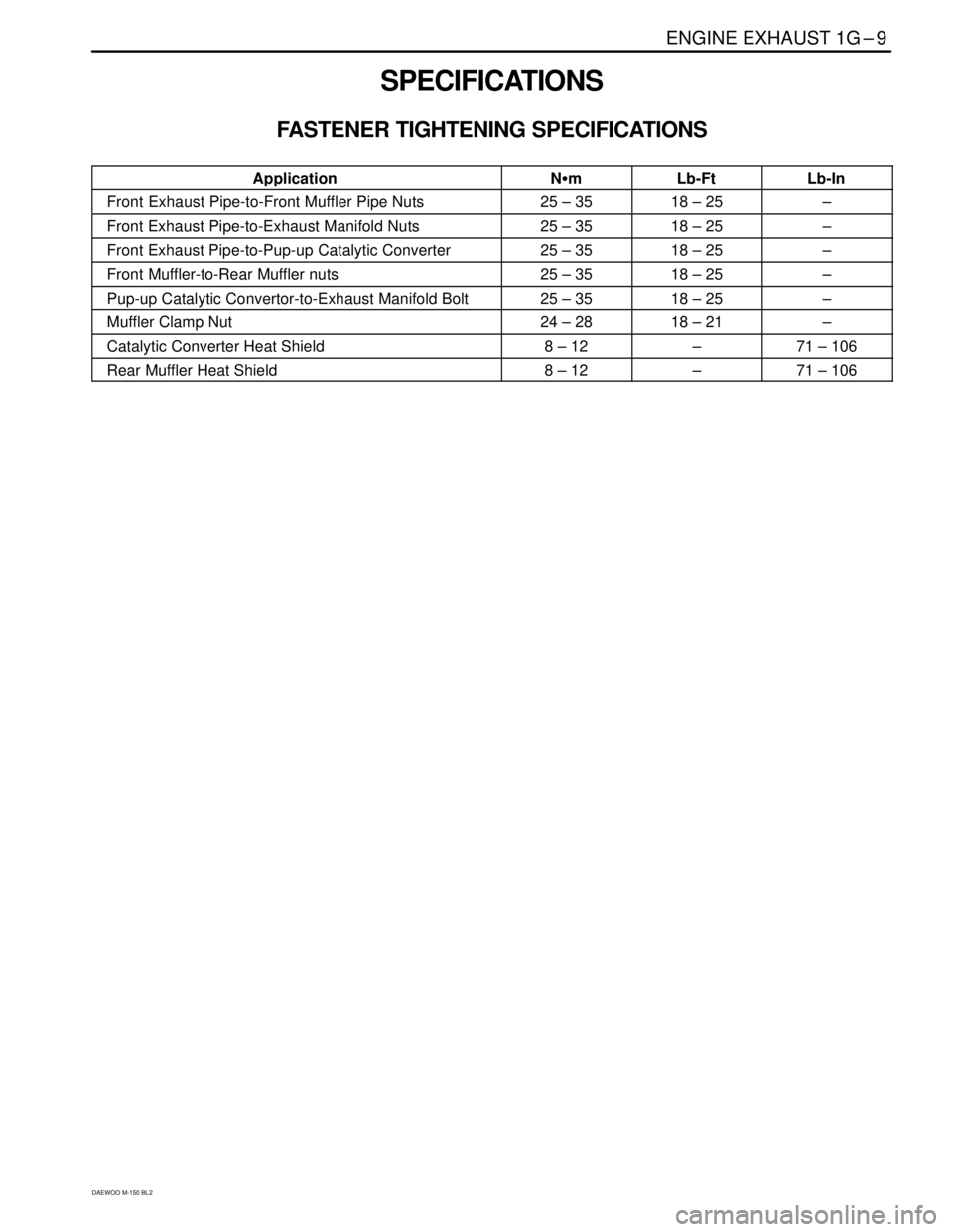
SPECIFICATIONS
FASTENER TIGHTENING SPECIFICATIONS
ApplicationN�mLb-FtLb-In
Front Exhaust Pipe-to-Front Muffler Pipe Nuts25 – 3518 – 25–
Front Exhaust Pipe-to-Exhaust Manifold Nuts25 – 3518 – 25–
Front Exhaust Pipe-to-Pup-up Catalytic Converter25 – 3518 – 25–
Front Muffler-to-Rear Muffler nuts25 – 3518 – 25–
Pup-up Catalytic Convertor-to-Exhaust Manifold Bolt25 – 3518 – 25–
Muffler Clamp Nut24 – 2818 – 21–
Catalytic Converter Heat Shield8 – 12–71 – 106
Rear Muffler Heat Shield8 – 12–71 – 106
Page 439 of 1184

2B – 2 WHEEL ALIGNMENT
DAEWOO M-150 BL2
DESCRIPTION AND OPERATION
FOUR WHEEL ALIGNMENT
The first responsibility of engineering is to design safe
steering and suspension systems. Each component
must be strong enough to withstand and absorb extreme
punishment. Both the steering system and the front and
the rear suspension must function geometrically with the
body mass.
The steering and the suspension systems require that
the front wheels self-return and that the tire rolling effort
and the road friction be held to a negligible force in order
to allow the customer to direct the vehicle with the least
effort and the most comfort.
A complete wheel alignment check should include mea-
surements of the rear toe and camber.
Four-wheel alignment assures that all four wheels will be
running in precisely the same direction.
When the vehicle is geometrically aligned, fuel economy
and tire life are at their peak, and steering and perfor-
mance are maximized.
TOE
D16A006A
Toe–in is the turning in of the tires, while toe–out is the
turning out of the tires from the geometric centerline or
thrust line. The toe ensures parallel rolling of the wheels.
The toe serves to offset the small deflections of the
wheel support system which occur when the vehicle is
rolling forward. The specified toe angle is the setting
which achieves–degrees (0�) of toe when the vehicle is
moving.
Incorrect toe-in or toe-out will cause tire wear and re-
duced fuel economy. As the individual steering and sus-
pension components wear from vehicle mileage,
additional toe will be needed to compensate for the
wear.
Always correct the toe dimension last.
CASTER
D16A008A
Caster is the tilting of the uppermost point of the steering
axis either forward or backward from the vertical when
viewed from the side of the vehicle. A backward tilt is
positive, and a forward tilt is negative. Caster influences
directional control of the steering but does not affect tire
wear. Weak springs or overloading a vehicle will affect
caster. One wheel with more positive caster will pull to-
ward the center of the car. This condition will cause the
car to move or lean toward the side with the least
amount of positive caster. Caster is measured in de-
grees and is not adjustable.
CAMBER
D16A007A
Camber is the tilting of the top of the tire from the vertical
when viewed from the front of the vehicle. When the
tires tilt outward, the camber is positive. When the tires
tilt inward, the camber is negative. The camber angle is
measured in degrees from the vertical. Camber in-
fluences both directional control and tire wear.
If the vehicle has too much positive camber, the outside
shoulder of the tire will wear. If the vehicle has too much
negative camber, the inside shoulder of the tire will wear.
Camber is measured in degrees and is not adjustable.


 connector.
5. Remove the exhaust mani")