2003 CHRYSLER VOYAGER cam sensor
[x] Cancel search: cam sensorPage 1382 of 2177
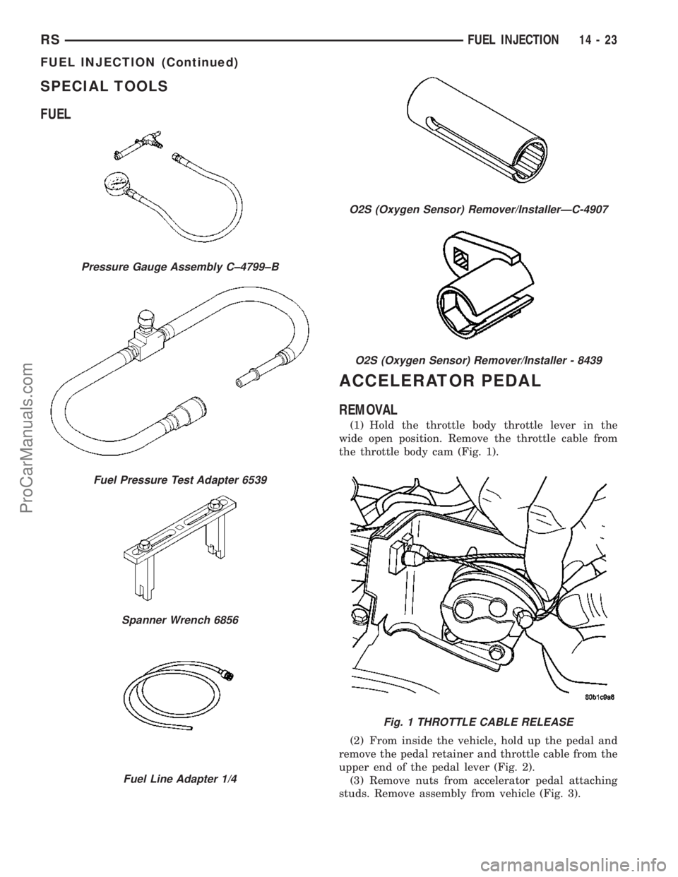
SPECIAL TOOLS
FUEL
ACCELERATOR PEDAL
REMOVAL
(1) Hold the throttle body throttle lever in the
wide open position. Remove the throttle cable from
the throttle body cam (Fig. 1).
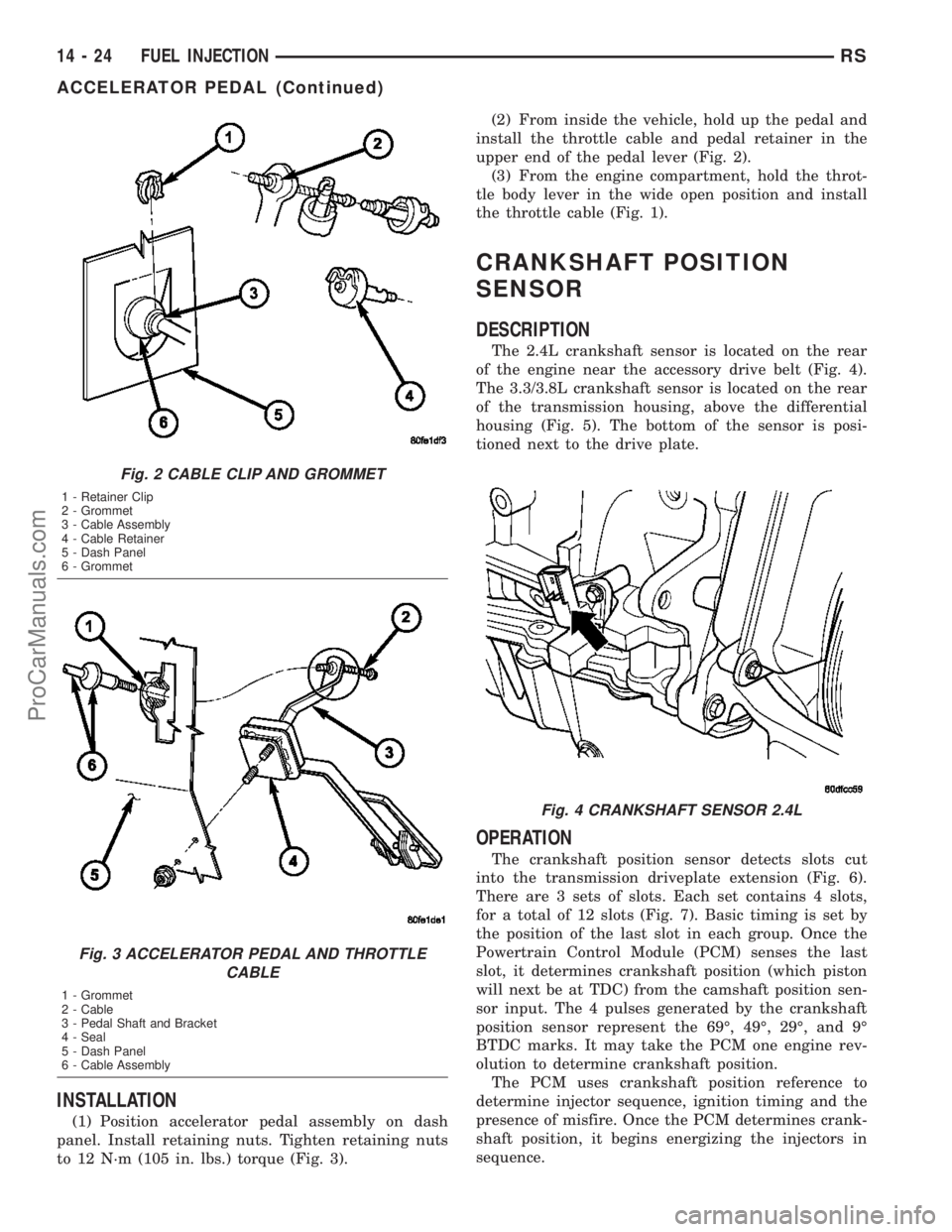
(2) From inside the vehicle, hold up the pedal and
remove the pedal retainer and throttle cable from the
upper end of the pedal lever (Fig. 2).
(3) Remove nuts from accelerator pedal attaching
studs. Remove assembly from vehicle (Fig. 3).
Pressure Gauge Assembly C±4799±B
Fuel Pressure Test Adapter 6539
Spanner Wrench 6856
Fuel Line Adapter 1/4
O2S (Oxygen Sensor) Remover/InstallerÐC-4907
O2S (Oxygen Sensor) Remover/Installer - 8439
Fig. 1 THROTTLE CABLE RELEASE
RSFUEL INJECTION14-23
FUEL INJECTION (Continued)
ProCarManuals.com
Page 1383 of 2177
INSTALLATION
(1) Position accelerator pedal assembly on dash
panel. Install retaining nuts. Tighten retaining nuts
to 12 N´m (105 in. lbs.) torque (Fig. 3).(2) From inside the vehicle, hold up the pedal and
install the throttle cable and pedal retainer in the
upper end of the pedal lever (Fig. 2).
(3) From the engine compartment, hold the throt-
tle body lever in the wide open position and install
the throttle cable (Fig. 1).
CRANKSHAFT POSITION
SENSOR
DESCRIPTION
The 2.4L crankshaft sensor is located on the rear
of the engine near the accessory drive belt (Fig. 4).
The 3.3/3.8L crankshaft sensor is located on the rear
of the transmission housing, above the differential
housing (Fig. 5). The bottom of the sensor is posi-
tioned next to the drive plate.
OPERATION
The crankshaft position sensor detects slots cut
into the transmission driveplate extension (Fig. 6).
There are 3 sets of slots. Each set contains 4 slots,
for a total of 12 slots (Fig. 7). Basic timing is set by
the position of the last slot in each group. Once the
Powertrain Control Module (PCM) senses the last
slot, it determines crankshaft position (which piston
will next be at TDC) from the camshaft position sen-
sor input. The 4 pulses generated by the crankshaft
position sensor represent the 69É, 49É, 29É, and 9É
BTDC marks. It may take the PCM one engine rev-
olution to determine crankshaft position.
The PCM uses crankshaft position reference to
determine injector sequence, ignition timing and the
presence of misfire. Once the PCM determines crank-
shaft position, it begins energizing the injectors in
sequence.
Fig. 2 CABLE CLIP AND GROMMET
1 - Retainer Clip
2 - Grommet
3 - Cable Assembly
4 - Cable Retainer
5 - Dash Panel
6 - Grommet
Fig. 3 ACCELERATOR PEDAL AND THROTTLE
CABLE
1 - Grommet
2 - Cable
3 - Pedal Shaft and Bracket
4 - Seal
5 - Dash Panel
6 - Cable Assembly
Fig. 4 CRANKSHAFT SENSOR 2.4L
14 - 24 FUEL INJECTIONRS
ACCELERATOR PEDAL (Continued)
ProCarManuals.com
Page 1389 of 2177
for the PCM to use as an intake air temperature sen-
sor and a battery temperature sensor.
The battery temperature information along with
data from monitored line voltage (B+), is used by the
PCM to vary the battery charging rate. System volt-
age will be higher at colder temperatures and is
gradually reduced at warmer temperatures.
The battery temperature information is also used
for OBD II diagnostics. Certain faults and OBD II
monitors are either enabled or disabled depending
upon the battery temperature sensor input (example:
disable purge, enable LDP). Most OBD II monitors
are disabled below 20ÉF.
MAP SENSOR
DESCRIPTION
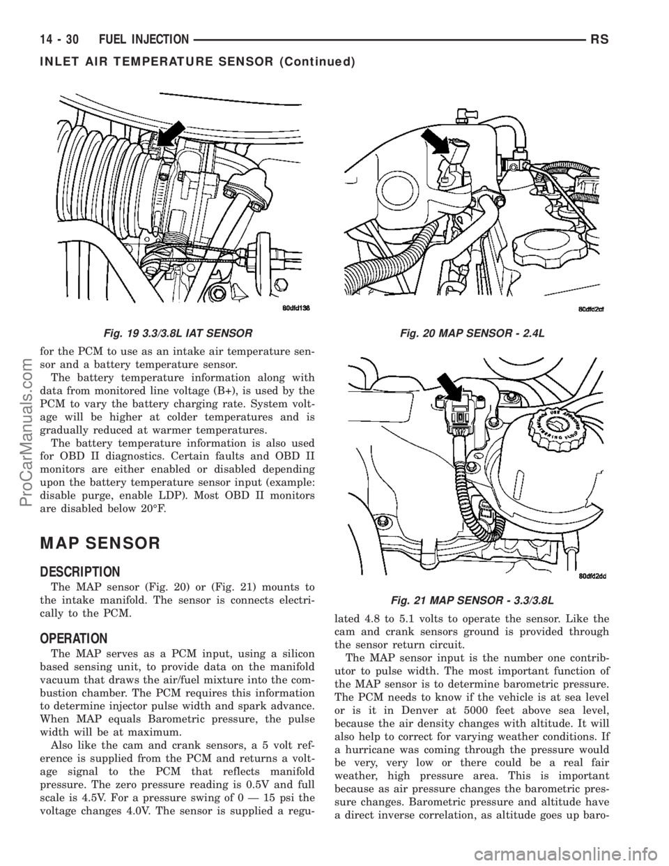
The MAP sensor (Fig. 20) or (Fig. 21) mounts to
the intake manifold. The sensor is connects electri-
cally to the PCM.
OPERATION
The MAP serves as a PCM input, using a silicon
based sensing unit, to provide data on the manifold
vacuum that draws the air/fuel mixture into the com-
bustion chamber. The PCM requires this information
to determine injector pulse width and spark advance.
When MAP equals Barometric pressure, the pulse
width will be at maximum.
Also like the cam and crank sensors, a 5 volt ref-
erence is supplied from the PCM and returns a volt-
age signal to the PCM that reflects manifold
pressure. The zero pressure reading is 0.5V and full
scale is 4.5V. For a pressure swing of0Ð15psithe
voltage changes 4.0V. The sensor is supplied a regu-lated 4.8 to 5.1 volts to operate the sensor. Like the
cam and crank sensors ground is provided through
the sensor return circuit.
The MAP sensor input is the number one contrib-
utor to pulse width. The most important function of
the MAP sensor is to determine barometric pressure.
The PCM needs to know if the vehicle is at sea level
or is it in Denver at 5000 feet above sea level,
because the air density changes with altitude. It will
also help to correct for varying weather conditions. If
a hurricane was coming through the pressure would
be very, very low or there could be a real fair
weather, high pressure area. This is important
because as air pressure changes the barometric pres-
sure changes. Barometric pressure and altitude have
a direct inverse correlation, as altitude goes up baro-
Fig. 19 3.3/3.8L IAT SENSORFig. 20 MAP SENSOR - 2.4L
Fig. 21 MAP SENSOR - 3.3/3.8L
14 - 30 FUEL INJECTIONRS
INLET AIR TEMPERATURE SENSOR (Continued)
ProCarManuals.com
Page 1394 of 2177
transmission control cable (when equipped) are con-
nected to the throttle body linkage arm.
A (factory adjusted) set screw is used to mechani-
cally limit the position of the throttle body throttle
plate.Never attempt to adjust the engine idle
speed using this screw.All idle speed functions are
controlled by the PCM.
REMOVAL
(1) Disconnect negative cable from battery cable.
(2) Remove air inlet to throttle body hose clamp.(3) Remove throttle and the speed control (if
equipped) cables from lever and bracket.
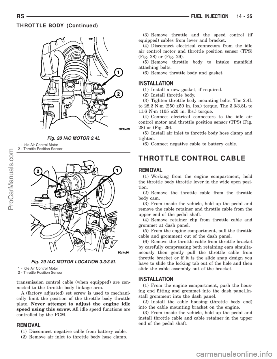
(4) Disconnect electrical connectors from the idle
air control motor and throttle position sensor (TPS)
(Fig. 28) or (Fig. 29).
(5) Remove throttle body to intake manifold
attaching bolts.
(6) Remove throttle body and gasket.
INSTALLATION
(1) Install a new gasket, if required.
(2) Install throttle body.
(3) Tighten throttle body mounting bolts. The 2.4L
to 28.2 N´m (250 50 in. lbs.) torque, The 3.3/3.8L to
11.6 N´m (105 20 in. lbs.) torque.
(4) Connect electrical connectors to the idle air
control motor and throttle position sensor (TPS) (Fig.
28) or (Fig. 29).
(5) Install air inlet to throttle body hose clamp and
tighten.
(6) Connect negative cable to battery cable.
THROTTLE CONTROL CABLE
REMOVAL
(1) Working from the engine compartment, hold
the throttle body throttle lever in the wide open posi-
tion.
(2) Remove the throttle cable from the throttle
body cam.
(3) From inside the vehicle, hold up the pedal and
remove the cable retainer and throttle cable from the
upper end of the pedal shaft.
(4) Remove retainer clip from throttle cable and
grommet at dash panel.
(5) From the engine compartment, pull the throttle
cable and gromment out of the dash panel.
(6) Remove the throttle cable from throttle bracket
by carefully compressing both retaining ears simulta-
neously then gently pull the throttle cable from
throttle bracket or if it is the slide snap design you
have to slide the locking tab out of the hole and then
slide the cable assembly out of the bracket.
INSTALLATION
(1) From the engine compartment, push the hous-
ing end fitting and grommet into the dash panel.In-
stall gromment into the dash panel.
(2) Install the cable housing (throttle body end)
into the cable mounting bracket on the engine.
(3) From inside the vehicle, hold up the pedal and
install throttle cable and cable retainer in the upper
end of the pedal shaft.
Fig. 28 IAC MOTOR 2.4L
1 - Idle Air Control Motor
2 - Throttle Position Sensor
Fig. 29 IAC MOTOR LOCATION 3.3/3.8L
1 - Idle Air Control Motor
2 - Throttle Position Sensor
RSFUEL INJECTION14-35
THROTTLE BODY (Continued)
ProCarManuals.com
Page 2113 of 2177
The following is a list of the monitored compo-
nents:
²Comprehensive Components
²Oxygen Sensor Monitor
²Oxygen Sensor Heater Monitor
²Catalyst Monitor
COMPREHENSIVE COMPONENTS
Along with the major monitors, OBD II requires
that the diagnostic system monitor any component
that could affect emissions levels. In many cases,
these components were being tested under OBD I.
The OBD I requirements focused mainly on testing
emissions-related components for electrical opens and
shorts.
However, OBD II also requires that inputs from
powertrain components to the PCM be tested for
rationality, and that outputs to powertrain compo-
nents from the PCM be tested forfunctionality.
Methods for monitoring the various Comprehensive
Component monitoring include:
(1) Circuit Continuity
²Open
²Shorted high
²Shorted to ground
(2) Rationality or Proper Functioning
²Inputs tested for rationality
²Outputs tested for functionality
NOTE: Comprehensive component monitors are
continuous. Therefore, enabling conditions do not
apply.
Input RationalityÐWhile input signals to the
PCM are constantly being monitored for electrical
opens and shorts, they are also tested for rationality.
This means that the input signal is compared against
other inputs and information to see if it makes sense
under the current conditions.
PCM sensor inputs that are checked for rationality
include:
²Manifold Absolute Pressure (MAP) Sensor
²Oxygen Sensor (O2S)
²Engine Coolant Temperature (ECT) Sensor
²Camshaft Position (CMP) Sensor
²Vehicle Speed Sensor
²Crankshaft Position (CKP) Sensor
²Intake/inlet Air Temperature (IAT) Sensor
²Throttle Position (TPS) Sensor
²Ambient Temperature Sensors
²Power Steering Switch
²Oxygen Sensor Heater
²Brake Switch
²Leak Detection Pump Switch or NVLD switch (if
equipped)
²P/N SwitchOutput FunctionalityÐPCM outputs are tested
for functionality in addition to testing for opens and
shorts. When the PCM provides a voltage to an out-
put component, it can verify that the command was
carried out by monitoring specific input signals for
expected changes. For example, when the PCM com-
mands the Idle Air Control (IAC) Motor to a specific
position under certain operating conditions, it expects
to see a specific (target) idle speed (RPM). If it does
not, it stores a DTC.
PCM outputs monitored for functionality include:
²Fuel Injectors
²Ignition Coils
²Idle Air Control
²Purge Solenoid
²EGR Solenoid (if equipped)
²LDP Solenoid or NVLD solenoid (if equipped)
²Radiator Fan Control
²Trans Controls
OXYGEN SENSOR (O2S) MONITOR
DESCRIPTIONÐEffective control of exhaust
emissions is achieved by an oxygen feedback system.
The most important element of the feedback system
is the O2S. The O2S is located in the exhaust path.
Once it reaches operating temperature 300É to 350ÉC
(572É to 662ÉF), the sensor generates a voltage that
is inversely proportional to the amount of oxygen in
the exhaust. When there is a large amount of oxygen
in the exhaust caused by a lean condition, the sensor
produces a low voltage, below 450 mV. When the oxy-
gen content is lower, caused by a rich condition, the
sensor produces a higher voltage, above 450mV (volt-
ages are offset by 2.5 volts on NGC vehicles).
The information obtained by the sensor is used to
calculate the fuel injector pulse width. The PCM is
programmed to maintain the optimum air/fuel ratio.
At this mixture ratio, the catalyst works best to
remove hydrocarbons (HC), carbon monoxide (CO)
and nitrous oxide (NOx) from the exhaust.
The O2S is also the main sensing element for the
EGR (if equipped), Catalyst and Fuel Monitors.
The O2S may fail in any or all of the following
manners:
²Slow response rate (Big Slope)
²Reduced output voltage (Half Cycle)
²Heater Performance
Slow Response Rate (Big Slope)ÐResponse rate
is the time required for the sensor to switch from
lean to rich signal output once it is exposed to a
richer than optimum A/F mixture or vice versa. As
the PCM adjusts the air/fuel ratio, the sensor must
be able to rapidly detect the change. As the sensor
ages, it could take longer to detect the changes in the
oxygen content of the exhaust gas. The rate of
change that an oxygen sensor experiences is called
25 - 2 EMISSIONS CONTROLRS
EMISSIONS CONTROL (Continued)
ProCarManuals.com
Page 2114 of 2177

ªBig Slopeº. The PCM checks the oxygen sensor volt-
age in increments of a few milliseconds.
Reduced Output Voltage (Half Cycle)ÐThe
output voltage of the O2S ranges from 0 to 1 volt
(voltages are offset by 2.5 volts on NGC vehicles). A
good sensor can easily generate any output voltage in
this range as it is exposed to different concentrations
of oxygen. To detect a shift in the A/F mixture (lean
or rich), the output voltage has to change beyond a
threshold value. A malfunctioning sensor could have
difficulty changing beyond the threshold value. Each
time the voltage signal surpasses the threshold, a
counter is incremented by one. This is called the Half
Cycle Counter.
Heater PerformanceÐThe heater is tested by a
separate monitor. Refer to the Oxygen Sensor Heater
Monitor.
OPERATIONÐAs the Oxygen Sensor signal
switches, the PCM monitors the half cycle and big
slope signals from the oxygen sensor. If during the
test neither counter reaches a predetermined value, a
malfunction is entered and Freeze Frame data is
stored. Only one counter reaching its predetermined
value is needed for the monitor to pass.
The Oxygen Sensor Monitor is a two trip monitor
that is tested only once per trip. When the Oxygen
Sensor fails the test in two consecutive trips, the
MIL is illuminated and a DTC is set. The MIL is
extinguished when the Oxygen Sensor monitor
passes in three consecutive trips. The DTC is erased
from memory after 40 consecutive warm-up cycles
without test failure.
Enabling ConditionsÐThe following conditions
must typically be met for the PCM to run the oxygen
sensor monitor:
²Battery voltage
²Engine temperature
²Engine run time
²Engine run time at a predetermined speed
²Engine run time at a predetermined speed and
throttle opening
²Transmission in gear and brake depressed (auto-
matic only)
²Fuel system in Closed Loop
²Long Term Adaptive (within parameters)
²Power Steering Switch in low PSI (no load)
²Engine at idle
²Fuel level above 15%
²Ambient air temperature
²Barometric pressure
²Engine RPM within acceptable range of desired
idle
Pending ConditionsÐThe Task Manager typi-
cally does not run the Oxygen Sensor Monitor if over-
lapping monitors are running or the MIL is
illuminated for any of the following:²Misfire Monitor
²Front Oxygen Sensor and Heater Monitor
²MAP Sensor
²Vehicle Speed Sensor
²Engine Coolant Temperature Sensor
²Throttle Position Sensor
²Engine Controller Self Test Faults
²Cam or Crank Sensor
²Injector and Coil
²Idle Air Control Motor
²EVAP Electrical
²EGR Solenoid Electrical (if equipped)
²Intake/inlet Air Temperature
²5 Volt Feed
ConflictÐThe Task Manager does not run the
Oxygen Sensor Monitor if any of the following condi-
tions are present:
²A/C ON (A/C clutch cycling temporarily sus-
pends monitor)
²Purge flow in progress
²Ethanol content learn is taking place and the
ethanol used once flag is set (if equipped)
SuspendÐThe Task Manager suspends maturing
a fault for the Oxygen Sensor Monitor if any of the
following are present:
²Oxygen Sensor Heater Monitor, Priority 1
²Misfire Monitor, Priority 2
OXYGEN SENSOR HEATER MONITOR
DESCRIPTIONÐIf there is an oxygen sensor
(O2S) DTC as well as a O2S heater DTC, the O2S
fault MUST be repaired first. After the O2S fault is
repaired, verify that the heater circuit is operating
correctly.
The voltage readings taken from the O2S are very
temperature sensitive. The readings are not accurate
below a sensor temperature of 300ÉC. Heating of the
O2S is done to allow the engine controller to shift to
closed loop control as soon as possible. The heating
element used to heat the O2S must be tested to
ensure that it is heating the sensor properly.
The heater element itself is not tested. The sensor
output is used to test the heater by isolating the
effect of the heater element on the O2S output volt-
age from the other effects. The resistance is normally
between 100 ohms and 4.5 megaohms. When oxygen
sensor temperature increases, the resistance in the
internal circuit decreases. The PCM sends a 5 volts
biased signal through the oxygen sensors to ground
this monitoring circuit. As the temperature increases,
resistance decreases and the PCM detects a lower
voltage at the reference signal. Inversely, as the tem-
perature decreases, the resistance increases and the
PCM detects a higher voltage at the reference signal.
The O2S circuit is monitored for a drop in voltage.
RSEMISSIONS CONTROL25-3
EMISSIONS CONTROL (Continued)
ProCarManuals.com
Page 2141 of 2177
ANTILOCK BRAKE SYSTEM -
DESCRIPTION........................5-75
ANTILOCK BRAKE SYSTEM - OPERATION . . 5-76
ANTILOCK BRAKE SYSTEM BLEEDING -
STANDARD PROCEDURE................5-78
ANTILOCK BRAKE SYSTEM (EXPORT) -
DESCRIPTION........................5-75
A-PILLAR LOWER EXTENSION TRIM -
INSTALLATION.......................23-73
A-PILLAR LOWER EXTENSION TRIM -
REMOVAL..........................23-73
A-PILLAR TRIM - INSTALLATION........23-73
A-PILLAR TRIM - REMOVAL............23-73
A-PILLAR-HEADER, OR B-PILLAR -
INSTALLATION.......................23-17
A-PILLAR-HEADER, OR B-PILLAR -
REMOVAL..........................23-17
APPLIQUE - INSTALLATION.............23-14
APPLIQUE - REMOVAL................23-14
ARM - DESCRIPTION, LOWER CONTROL . . . 2-12
ARM - INSPECTION, LOWER CONTROL....2-14
ARM - INSTALLATION, LOWER CONTROL . . 2-15
ARM - INSTALLATION, REAR WIPER.....8R-14
ARM - INSTALLATION, TORQUE..........3-44
ARM - OPERATION, LOWER CONTROL.....2-12
ARM - REMOVAL, LOWER CONTROL......2-12
ARM - REMOVAL, REAR WIPER.........8R-14
ARM - REMOVAL, TORQUE..............3-44
ARM ALIGNMENT - STANDARD
PROCEDURE, FRONT WIPER............8R-8
ARM (REAR BUSHING - HYDRO) -
ASSEMBLY, LOWER CONTROL...........2-14
ARM (REAR BUSHING - HYDRO) -
DISASSEMBLY, LOWER CONTROL........2-14
ARM (REAR BUSHING - STANDARD) -
ASSEMBLY, LOWER CONTROL...........2-14
ARM (REAR BUSHING - STANDARD) -
DISASSEMBLY, LOWER CONTROL........2-13
ARMREST - INSTALLATION.............23-90
ARMREST - REMOVAL................23-90
ARMS - DESCRIPTION, ROCKER........9-109
ARMS - INSPECTION, ROCKER...........9-35
ARMS - INSTALLATION, FRONT WIPER....8R-9
ARMS - INSTALLATION, ROCKER.........9-35
ARMS - OPERATION, ROCKER..........9-109
ARMS - REMOVAL, FRONT WIPER........8R-9
ARMS - REMOVAL, ROCKER.............9-34
ARMS AND SHAFT - ASSEMBLY,
ROCKER............................9-109
ARMS AND SHAFT - DISASSEMBLY,
ROCKER............................9-109
ARMS AND SHAFT - INSTALLATION,
ROCKER............................9-110
ARMS AND SHAFT - REMOVAL, ROCKER . . 9-109
ASSIST HANDLE - INSTALLATION........23-73
ASSIST HANDLE - REMOVAL...........23-73
ASSIST STRAP - INSTALLATION, FRONT
SEATBACK..........................23-91
ASSIST STRAP - REMOVAL, FRONT
SEATBACK..........................23-91
ATC - OPERATION, THREE ZONE.........24-3
ATC - OPERATION, TWO ZONE.........24-106
ATTACHED - INSTALLATION, EXTERIOR
NAME PLATES - ADHESIVE.............23-50
ATTACHED - INSTALLATION, EXTERIOR
NAME PLATES - TAPE.................23-50
ATTACHED - REMOVAL, EXTERIOR NAME
PLATES - ADHESIVE..................23-50
ATTACHED - REMOVAL, EXTERIOR NAME
PLATES - TAPE ......................23-50
AUDIO - DIAGNOSIS AND TESTING.......8A-2
AUDIO/VIDEO - DESCRIPTION...........8A-1
AUDIO/VIDEO - OPERATION.............8A-2
AUTO SHUT DOWN RELAY -
DESCRIPTION.........................8I-3
AUTO SHUT DOWN RELAY - OPERATION . . . 8I-3
AUTOMATIC ADJUSTER - DIAGNOSIS
AND TESTING, DRUM BRAKE
............5-13
AUTOMATIC ADJUSTER TENSION
RELEASE - STANDARD PROCEDURE,
PARKING BRAKE
......................5-58
AUTOMATIC ADJUSTER TENSION RESET
- STANDARD PROCEDURE, PARKING
BRAKE
..............................5-59
AUTOMATIC DAY / NIGHT MIRROR -
DESCRIPTION
.......................8N-47
AUTOMATIC DAY / NIGHT MIRROR -
DIAGNOSIS AND TESTING
.............8N-47AUTOMATIC DAY / NIGHT MIRROR -
OPERATION.........................8N-47
AUTOMATIC TEMPERATURE CONTROL -
DESCRIPTION........................24-2
AUTOMATIC TRANSAXLE -
DESCRIPTION, 41TE.................21-117
AUTOMATIC TRANSAXLE - OPERATION,
41TE.............................21-119
AUTOMATIC TRANSAXLE, SPECIAL
TOOLS - 41TE......................21-183
AUTOSTICK SWITCH - DESCRIPTION....21-189
AUTOSTICK SWITCH - OPERATION......21-189
AWD - INSTALLATION..............2-39,2-44
AWD - INSTALLATION, REAR WHEEL
SPEED SENSOR.......................5-80
AWD - REMOVAL.................2-38,2-44
AWD - REMOVAL, REAR WHEEL SPEED
SENSOR............................5-80
AWD AND HEAVY DUTY - INSTALLATION . . . 2-35
AWD AND HEAVY DUTY - REMOVAL......2-35
AXLE SEALS - INSTALLATION...........21-61
AXLE SEALS - REMOVAL..............21-61
B OR C-PILLAR - INSTALLATION, SEAT
BELT HEIGHT ADJUSTER..............8O-12
B OR C-PILLAR - REMOVAL, SEAT BELT
HEIGHT ADJUSTER...................8O-12
BACK - INSTALLATION, BENCH SEAT....23-101
BACK - QUAD BUCKET - INSTALLATION,
BUCKET SEAT.......................23-97
BACK - QUAD BUCKET - REMOVAL,
BUCKET SEAT.........................23-97
BACK - REMOVAL, BENCH SEAT........23-101
BACK COVER - INSTALLATION, BENCH
SEAT .............................23-102
BACK COVER - REMOVAL, BENCH SEAT . . 23-102
BACK HINGE - REMOVAL, BENCH SEAT . . 23-100
BACK HINGE COVERS - QUAD BUCKET,
50/50 SPLIT, BENCH - INSTALLATION,
SEAT .............................23-100
BACK HINGE COVERS - QUAD BUCKET,
50/50 SPLIT, BENCH - REMOVAL, SEAT . . 23-100
BACKING PLATE - INSTALLATION,
STEERING COLUMN COVER............23-69
BACKING PLATE - REMOVAL, STEERING
COLUMN COVER.....................23-69
BACK-UP LAMP SWITCH -
INSTALLATION.......................21-62
BACK-UP LAMP SWITCH - REMOVAL.....21-62
BAG RETAINER - INSTALLATION,
PLASTIC GROCERY..................23-103
BAG RETAINER - REMOVAL, PLASTIC
GROCERY.........................23-103
BALANCE - STANDARD PROCEDURE,
TIRE AND WHEEL.....................22-5
BALANCE SHAFTS AND CARRIER
ASSEMBLY - DESCRIPTION.............9-69
BALANCE SHAFTS AND CARRIER
ASSEMBLY - INSTALLATION.............9-72
BALANCE SHAFTS AND CARRIER
ASSEMBLY - OPERATION...............9-69
BALANCE SHAFTS AND CARRIER
ASSEMBLY - REMOVAL.................9-69
BALL BEARING - INSTALLATION, END
COVER.............................21-10
BALL BEARING - REMOVAL, END COVER . . . 21-9
BALL JOINT - DESCRIPTION, LOWER......2-10
BALL JOINT - DIAGNOSIS AND TESTING,
LOWER.............................2-10
BALL JOINT - OPERATION, LOWER.......2-10
BALL JOINT SEAL BOOT - INSTALLATION . . 2-11
BALL JOINT SEAL BOOT - REMOVAL......2-11
BAR - DESCRIPTION, STABILIZER....2-16,2-43
BAR - DESCRIPTION, TRACK............2-44
BAR - INSPECTION, STABILIZER..........2-17
BAR - INSTALLATION, STABILIZER........2-17
BAR - INSTALLATION, TRACK............2-45
BAR - OPERATION, STABILIZER......2-16,2-44
BAR - OPERATION, TRACK..............2-44
BAR - REMOVAL, STABILIZER...........2-17
BAR - REMOVAL, TRACK...............2-44
BAR CUSHION - INSTALLATION,
STABILIZER
...........................2-4
BAR CUSHION - REMOVAL, STABILIZER
....2-4
BASE BRAKE BLEEDING - STANDARD
PROCEDURE
..........................5-7
BASE BRAKE SYSTEM - DIAGNOSIS AND
TESTING
.............................5-4
BASE BRAKE SYSTEM, SPECIAL TOOLS
....5-10BASE BRAKES - DESCRIPTION............5-3
BASE BRAKES - OPERATION..............5-3
BASE BRAKES (EXPORT) - DESCRIPTION . . . 5-3
BASE COAT/CLEARCOAT FINISH -
DESCRIPTION.......................23-84
BATTERY - DESCRIPTION...............8F-7
BATTERY - DIAGNOSIS AND TESTING.....8F-9
BATTERY - OPERATION.................8F-9
BATTERY - REMOVAL.................8F-15
BATTERY CABLE - DIAGNOSIS AND
TESTING...........................8F-16
BATTERY CABLES - DESCRIPTION.......8F-16
BATTERY CABLES - INSTALLATION.......8F-18
BATTERY CABLES - OPERATION.........8F-16
BATTERY CABLES - REMOVAL..........8F-18
BATTERY CHARGING - STANDARD
PROCEDURE, CONVENTIONAL..........8F-11
BATTERY CHARGING - STANDARD
PROCEDURE, SPIRAL PLATE............8F-10
BATTERY ELECTROLYTE LEVEL -
STANDARD PROCEDURE, CHECKING.....8F-14
BATTERY HOLDDOWN - DESCRIPTION....8F-15
BATTERY HOLDDOWN - INSTALLATION . . . 8F-16
BATTERY HOLDDOWN - OPERATION.....8F-15
BATTERY HOLDDOWN - REMOVAL.......8F-16
BATTERY REPLACEMENT - STANDARD
PROCEDURE........................8N-42
BATTERY, SPECIFICATIONS.............8N-43
BATTERY SYSTEM - CLEANING...........8F-5
BATTERY SYSTEM - DESCRIPTION........8F-1
BATTERY SYSTEM - DIAGNOSIS AND
TESTING............................8F-2
BATTERY SYSTEM - INSPECTION.........8F-5
BATTERY SYSTEM - OPERATION.........8F-2
BATTERY SYSTEM - SPECIFICATIONS......8F-6
BATTERY SYSTEM SPECIAL TOOLS,
SPECIAL TOOLS......................8F-7
BATTERY TEMPERATURE SENSOR -
DESCRIPTION.......................8F-23
BATTERY TEMPERATURE SENSOR -
OPERATION.........................8F-23
BATTERY TEMPERATURE SENSOR -
REMOVAL..........................8F-23
BATTERY TEMPERATURE SENSOR -
SPECIFICATIONS.....................8F-22
BATTERY TRAY - DESCRIPTION.........8F-18
BATTERY TRAY - INSTALLATION.........8F-19
BATTERY TRAY - OPERATION...........8F-19
BATTERY TRAY - REMOVAL............8F-19
BEARING - DESCRIPTION, HUB.......2-30,2-5
BEARING - DIAGNOSIS AND TESTING,
HUB.............................2-30,2-5
BEARING - INSTALLATION, CLUTCH
RELEASE LEVER.......................6-7
BEARING - INSTALLATION, END COVER
BALL..............................21-10
BEARING - INSTALLATION, HUB.......2-32,2-5
BEARING - OPERATION, HUB.........2-30,2-5
BEARING - REMOVAL, CLUTCH RELEASE
LEVER...............................6-6
BEARING - REMOVAL, END COVER BALL . . . 21-9
BEARING - REMOVAL, HUB..........2-31,2-5
BEARING CLEARANCE - STANDARD
PROCEDURE, MEASURING
CONNECTING ROD...................9-120
BEARING CLEARANCE USING
PLASTIGAGE - STANDARD
PROCEDURE, MEASURING..........9-12,9-84
BEARING FITTING - STANDARD
PROCEDURE, MAIN...................9-123
BEARING PRELOAD - ADJUSTMENT,
DIFFERENTIAL......................21-199
BEARINGS - INSTALLATION,
CRANKSHAFT MAIN..................9-124
BEARINGS - REMOVAL, CRANKSHAFT
MAIN..............................9-124
BEARINGS (IN BLOCK) - DESCRIPTION,
CAMSHAFT.........................9-115
BEARINGS (IN BLOCK) - INSPECTION,
CAMSHAFT.........................9-115
BEARINGS (IN BLOCK) - INSTALLATION,
CAMSHAFT
.........................9-115
BEARINGS (IN BLOCK) - OPERATION,
CAMSHAFT
.........................9-115
BEARINGS (IN BLOCK) - REMOVAL,
CAMSHAFT
.........................9-115
BELLCRANK - INSTALLATION
...........23-34
BELLCRANK - REMOVAL
...............23-34
2 INDEXRS
Description Group-Page Description Group-Page Description Group-Page
ProCarManuals.com
Page 2144 of 2177
BUCKET SEAT BACK - QUAD BUCKET -
INSTALLATION.......................23-97
BUCKET SEAT BACK - QUAD BUCKET -
REMOVAL..........................23-97
BUCKET SEAT RISER - INSTALLATION,
QUAD..............................23-96
BUCKET SEAT RISER - REMOVAL, QUAD . . 23-96
BUCKET SEAT SIDE SHIELD - NO CUP
HOLDER - INSTALLATION, QUAD........23-96
BUCKET SEAT SIDE SHIELD - NO CUP
HOLDER - REMOVAL, QUAD............23-96
BUCKET SEAT SIDE SHIELD/CUP
HOLDER - INSTALLATION, QUAD........23-95
BUCKET SEAT SIDE SHIELD/CUP
HOLDER - REMOVAL, QUAD............23-95
BUCKLE - FIRST ROW - BENCH -
INSTALLATION, SEAT BELT.............8O-12
BUCKLE - FIRST ROW - BENCH -
REMOVAL, SEAT BELT................8O-12
BUCKLE - FIRST ROW INBOARD - QUAD
BUCKET - INSTALLATION, SEAT BELT....8O-11
BUCKLE - FIRST ROW INBOARD - QUAD
BUCKET - REMOVAL, SEAT BELT........8O-11
BUCKLE - FRONT INBOARD -
INSTALLATION, SEAT BELT.............8O-11
BUCKLE - FRONT INBOARD - REMOVAL,
SEAT BELT .........................8O-11
BUCKLE - SECOND ROW - THREE
PASSENGER BENCH - INSTALLATION,
SEAT BELT .........................8O-14
BUCKLE - SECOND ROW - THREE
PASSENGER BENCH - REMOVAL, SEAT
BELT ..............................8O-14
BUCKLE - SECOND ROW INBOARD -
50/50 BENCH - INSTALLATION, SEAT
BELT ..............................8O-12
BUCKLE - SECOND ROW INBOARD -
50/50 BENCH - REMOVAL, SEAT BELT....8O-12
BUMPER - DESCRIPTION, JOUNCE........2-35
BUMPER - INSTALLATION, STOP........23-25
BUMPER - OPERATION, JOUNCE.........2-35
BUMPER - REMOVAL, STOP............23-25
BUMPER BEZEL - INSTALLATION,
SLIDING DOOR STOP.................23-25
BUMPER BEZEL - REMOVAL, SLIDING
DOOR STOP........................23-25
BUMPER REINFORCEMENT -
INSTALLATION, FRONT.................13-2
BUMPER REINFORCEMENT -
INSTALLATION, REAR..................13-3
BUMPER REINFORCEMENT - REMOVAL,
FRONT..............................13-2
BUMPER REINFORCEMENT - REMOVAL,
REAR...............................13-3
BUS COMMUNICATION RECEIVE - PCM
INPUT - OPERATION, DATA.............8E-15
BUS, OPERATION - PROGRAMMABLE
COMMUNICATIONS INTERFACE (PCI).....14-21
BUSHING - INSTALLATION, LEAF SPRING
FRONT..............................2-29
BUSHING - REMOVAL, LEAF SPRING
FRONT..............................2-28
BUSHINGS - INSTALLATION, FRONT
CROSSMEMBER MOUNT...............13-12
BUSHINGS - REMOVAL, FRONT
CROSSMEMBER MOUNT...............13-12
BUSHINGS (DISC/DISC BRAKES) -
ASSEMBLY, CALIPER GUIDE PIN.........5-25
BUSHINGS (DISC/DISC BRAKES) -
DISASSEMBLY, CALIPER GUIDE PIN.......5-24
CABLE - CROSSOVER - INSTALLATION,
GEARSHIFT.........................21-76
CABLE - CROSSOVER - REMOVAL,
GEARSHIFT.........................21-73
CABLE - DESCRIPTION.................8P-4
CABLE - DESCRIPTION, ANTENNA BODY . . . 8A-4
CABLE - DESCRIPTION, SPARK PLUG.....8I-10
CABLE - DIAGNOSIS AND TESTING,
ANTENNA BODY......................8A-4
CABLE - DIAGNOSIS AND TESTING,
BATTERY...........................8F-16
CABLE - INSTALLATION................8P-4
CABLE - INSTALLATION, ANTENNA BODY
. . 8A-6
CABLE - INSTALLATION, FRONT
..........5-64
CABLE - INSTALLATION, GEAR SHIFT
....21-205
CABLE - INSTALLATION, HOLD OPEN
LATCH
.............................23-38
CABLE - INSTALLATION, INSIDE HANDLE
. . 23-37CABLE - INSTALLATION, INSTRUMENT
PANEL ANTENNA......................8A-9
CABLE - INSTALLATION, LATCH RELEASE . 23-61
CABLE - INSTALLATION, OUTSIDE
HANDLE............................23-36
CABLE - INSTALLATION, PARKING
BRAKE LEVER AND FRONT..............5-66
CABLE - INSTALLATION, THROTTLE
CONTROL..........................14-35
CABLE - OPERATION...................8P-4
CABLE - OPERATION, ANTENNA BODY.....8A-4
CABLE - REMOVAL....................8P-4
CABLE - REMOVAL, ANTENNA BODY......8A-5
CABLE - REMOVAL, FRONT..............5-64
CABLE - REMOVAL, GEAR SHIFT.......21-204
CABLE - REMOVAL, HOLD OPEN LATCH . . . 23-37
CABLE - REMOVAL, INSIDE HANDLE.....23-37
CABLE - REMOVAL, INSTRUMENT PANEL
ANTENNA...........................8A-8
CABLE - REMOVAL, LATCH RELEASE.....23-60
CABLE - REMOVAL, OUTSIDE HANDLE....23-36
CABLE - REMOVAL, PARKING BRAKE
LEVER AND FRONT....................5-65
CABLE - REMOVAL, THROTTLE
CONTROL..........................14-35
CABLE - SELECTOR - INSTALLATION,
GEARSHIFT.........................21-84
CABLE - SELECTOR - REMOVAL,
GEARSHIFT.........................21-81
CABLE ADJUSTMENT, ADJUSTMENTS -
GEARSHIFT........................21-206
CABLE ADJUSTMENT, INSTALLATION -
SYNCHRONIZING...............23-101,23-87
CABLE (FRONT) - INSTALLATION,
PARKING BRAKE......................5-63
CABLE (FRONT) - REMOVAL, PARKING
BRAKE..............................5-59
CABLE (INTERMEDIATE) -
INSTALLATION, PARKING BRAKE.........5-63
CABLE (INTERMEDIATE) - REMOVAL,
PARKING BRAKE......................5-60
CABLE (LEFT REAR) - INSTALLATION,
PARKING BRAKE......................5-64
CABLE (LEFT REAR) - REMOVAL,
PARKING BRAKE......................5-62
CABLE RESISTANCE, SPECIFICATIONS -
SPARK PLUG.........................8I-2
CABLE (RIGHT REAR) - INSTALLATION,
PARKING BRAKE......................5-63
CABLE (RIGHT REAR) - REMOVAL,
PARKING BRAKE......................5-60
CABLES - ADJUSTMENT, PARKING
BRAKE..............................5-64
CABLES - DESCRIPTION, BATTERY.......8F-16
CABLES - INSTALLATION, BATTERY......8F-18
CABLES - OPERATION, BATTERY........8F-16
CABLES - REMOVAL, BATTERY..........8F-18
CALIBRATION - STANDARD PROCEDURE,
COMPASS...........................8M-3
CALIBRATION - STANDARD PROCEDURE,
HEATER-A/C CONTROL.................24-8
CALIPER - CLEANING..............5-25,5-29
CALIPER - INSPECTION............5-25,5-29
CALIPER - INSTALLATION, REAR DISC
BRAKE..............................5-30
CALIPER - REMOVAL, REAR DISC
BRAKE..............................5-27
CALIPER ADAPTER - INSTALLATION,
FRONT DISC BRAKE...................5-31
CALIPER ADAPTER - REMOVAL, FRONT
DISC BRAKE.........................5-31
CALIPER (DISC/DISC BRAKES) -
INSTALLATION, FRONT DISC BRAKE......5-27
CALIPER (DISC/DISC BRAKES) -
REMOVAL, FRONT DISC BRAKE..........5-24
CALIPER (DISC/DRUM BRAKES) -
INSTALLATION, FRONT DISC BRAKE......5-27
CALIPER (DISC/DRUM BRAKES) -
REMOVAL, FRONT DISC BRAKE
..........5-24
CALIPER GUIDE PIN BUSHINGS
(DISC/DISC BRAKES) - ASSEMBLY
........5-25
CALIPER GUIDE PIN BUSHINGS
(DISC/DISC BRAKES) - DISASSEMBLY
.....5-24
CALIPER GUIDE PINS (DISC/DRUM
BRAKES) - INSTALLATION, DISC
BRAKE
..............................5-31
CALIPER GUIDE PINS (DISC/DRUM
BRAKES) - REMOVAL, DISC BRAKE
.......5-31CALIPER PISTON AND SEAL -
ASSEMBLY......................5-26,5-29
CALIPER PISTON AND SEAL -
DISASSEMBLY....................5-24,5-28
CAMSHAFT & BEARINGS (IN BLOCK) -
DESCRIPTION.......................9-115
CAMSHAFT & BEARINGS (IN BLOCK) -
INSPECTION........................9-115
CAMSHAFT & BEARINGS (IN BLOCK) -
INSTALLATION.......................9-115
CAMSHAFT & BEARINGS (IN BLOCK) -
OPERATION.........................9-115
CAMSHAFT & BEARINGS (IN BLOCK) -
REMOVAL..........................9-115
CAMSHAFT END PLAY - STANDARD
PROCEDURE, MEASURING..............9-29
CAMSHAFT OIL SEAL(S) - INSTALLATION . . 9-28
CAMSHAFT OIL SEAL(S) - REMOVAL......9-27
CAMSHAFT POSITION SENSOR -
DESCRIPTION.........................8I-3
CAMSHAFT POSITION SENSOR -
OPERATION..........................8I-3
CAMSHAFT SPROCKET - INSTALLATION,
TIMING CHAIN.......................9-157
CAMSHAFT SPROCKET - REMOVAL,
TIMING CHAIN.......................9-156
CAMSHAFT SPROCKETS - INSTALLATION . . 9-65
CAMSHAFT SPROCKETS - REMOVAL......9-64
CAMSHAFT(S) - CLEANING..............9-29
CAMSHAFT(S) - DESCRIPTION...........9-28
CAMSHAFT(S) - INSPECTION............9-30
CAMSHAFT(S) - INSTALLATION..........9-30
CAMSHAFT(S) - OPERATION.............9-28
CAMSHAFT(S) - REMOVAL..............9-29
CANISTER - DESCRIPTION, VAPOR......25-18
CANISTER - INSTALLATION, REAR EVAP . . 25-20
CANISTER - OPERATION, VAPOR........25-18
CANISTER - REMOVAL, REAR EVAP......25-19
CAP - DESCRIPTION, FUEL FILLER.......25-12
CAP - DESCRIPTION, RADIATOR
PRESSURE..........................7-26
CAP - INSTALLATION, INSTRUMENT
PANEL END.........................23-67
CAP - OPERATION, FUEL FILLER........25-12
CAP - OPERATION, RADIATOR
PRESSURE..........................7-27
CAP - REMOVAL, INSTRUMENT PANEL
END ...............................23-67
CAP TESTING - DIAGNOSIS AND
TESTING, COOLING SYSTEM
PRESSURE..........................7-27
CAP TO FILLER NECK SEAL -
DIAGNOSIS AND TESTING, RADIATOR.....7-27
CAPACITIES - SPECIFICATIONS, FLUID......0-6
CARE - CLEANING, ALUMINUM WHEEL . . . 22-18
CARPETS AND FLOOR MATS -
INSTALLATION.......................23-75
CARPETS AND FLOOR MATS - REMOVAL . 23-74
CARRIER ASSEMBLY - DESCRIPTION,
BALANCE SHAFTS.....................9-69
CARRIER ASSEMBLY - INSTALLATION,
BALANCE SHAFTS.....................9-72
CARRIER ASSEMBLY - OPERATION,
BALANCE SHAFTS.....................9-69
CARRIER ASSEMBLY - REMOVAL,
BALANCE SHAFTS.....................9-69
CARRIER SEAL - INSTALLATION,
DIFFERENTIAL........................21-9
CARRIER SEAL - REMOVAL,
DIFFERENTIAL........................21-9
CATALYTIC CONVERTER - DESCRIPTION . . . 11-4
CATALYTIC CONVERTER - INSPECTION....11-5
CATALYTIC CONVERTER - INSTALLATION . . . 11-6
CATALYTIC CONVERTER - OPERATION.....11-4
CATALYTIC CONVERTER - REMOVAL......11-5
CAUSES - DIAGNOSIS AND TESTING,
COMMON PROBLEM..................21-30
CAUTION - CAUTIONS..................5-78
CAUTION, A/C PLUMBING..............24-61
CAUTION, DESCRIPTION.................5-4
CAUTION, DESCRIPTION...............19-37
CAUTION, SENSOR - TPM..............22-10
CAUTIONS, CAUTION..................5-78
CAUTIONS, WARNING - WARNINGS
. 19-10,19-27
CD CHANGER - DESCRIPTION
...........8A-7
CD CHANGER - INSTALLATION
...........8A-8
CD CHANGER - OPERATION
.............8A-7
CD CHANGER - REMOVAL
..............8A-8
RSINDEX5
Description Group-Page Description Group-Page Description Group-Page
ProCarManuals.com