2003 CHRYSLER VOYAGER cam sensor
[x] Cancel search: cam sensorPage 1231 of 2177
LUBRICATION
DESCRIPTION
The lubrication system is a full-flow filtration,
pressure feed type. The oil pump is mounted in the
front engine cover and driven by the crankshaft.
OPERATION
Engine oil drawn up through the pickup tube and is
pressurized by the oil pump and routed through the
full-flow filter to the main oil gallery running the
length of the cylinder block. A diagonal hole in each
bulkhead feeds oil to each main bearing. Drilled pas-
sages within the crankshaft route oil from main bear-
ing journals to connecting rod journals. Balance shaft
lubrication is provided through an oil passage from
the number one main bearing cap through the balance
shaft carrier support leg. This passage directly sup-
plies oil to the front bearings and internal machined
passages in the shafts that routes oil from front to the
rear shaft bearing journals. A vertical hole at the
number five bulkhead routes pressurized oil through a
restrictor (integral to the cylinder head gasket) up
past a cylinder head bolt to an oil gallery running the
length of the cylinder head. The camshaft journals arepartially slotted to allow a predetermined amount of
pressurized oil to pass into the bearing cap cavities.
Lubrication of the camshaft lobes are provided by
small holes in the camshaft bearing caps that are
directed towards each lobe. Oil returning to the pan
from pressurized components supplies lubrication to
the valve stems. Cylinder bores and wrist pins are
splash lubricated from directed slots on the connecting
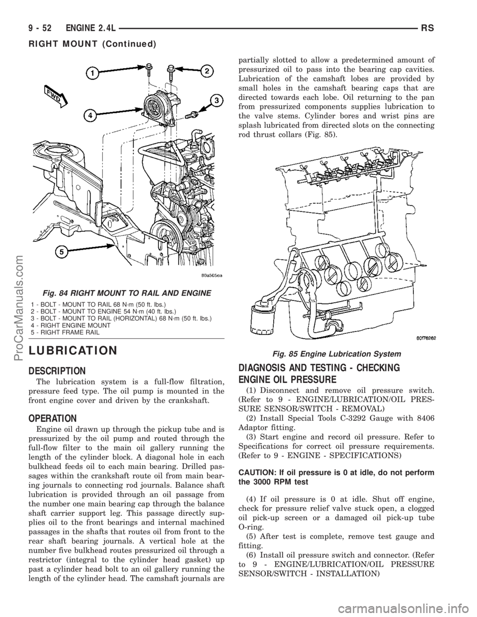
rod thrust collars (Fig. 85).
DIAGNOSIS AND TESTING - CHECKING
ENGINE OIL PRESSURE
(1) Disconnect and remove oil pressure switch.
(Refer to 9 - ENGINE/LUBRICATION/OIL PRES-
SURE SENSOR/SWITCH - REMOVAL)
(2) Install Special Tools C-3292 Gauge with 8406
Adaptor fitting.
(3) Start engine and record oil pressure. Refer to
Specifications for correct oil pressure requirements.
(Refer to 9 - ENGINE - SPECIFICATIONS)
CAUTION: If oil pressure is 0 at idle, do not perform
the 3000 RPM test
(4) If oil pressure is 0 at idle. Shut off engine,
check for pressure relief valve stuck open, a clogged
oil pick-up screen or a damaged oil pick-up tube
O-ring.
(5) After test is complete, remove test gauge and
fitting.
(6) Install oil pressure switch and connector. (Refer
to 9 - ENGINE/LUBRICATION/OIL PRESSURE
SENSOR/SWITCH - INSTALLATION)
Fig. 84 RIGHT MOUNT TO RAIL AND ENGINE
1 - BOLT - MOUNT TO RAIL 68 N´m (50 ft. lbs.)
2 - BOLT - MOUNT TO ENGINE 54 N´m (40 ft. lbs.)
3 - BOLT - MOUNT TO RAIL (HORIZONTAL) 68 N´m (50 ft. lbs.)
4 - RIGHT ENGINE MOUNT
5 - RIGHT FRAME RAIL
Fig. 85 Engine Lubrication System
9 - 52 ENGINE 2.4LRS
RIGHT MOUNT (Continued)
ProCarManuals.com
Page 1266 of 2177
(11) Disconnect the throttle cables from the throt-
tle body.
(12) Disconnect the MAP, IAC, and TPS electrical
connectors.
(13) Disconnect the EGR transducer electrical con-
nector (if equipped).
(14) Disconnect the vacuum hoses from throttle
body.
(15) Disconnect the brake booster and speed con-
trol vacuum hoses.
(16) Disengage wire harness clip from the right
side engine mount.
(17) Remove the power steering reservoir from
mounting position and set aside.Do notdisconnect
hose.
(18) Disconnect ground strap from rear of cylinder
head.
(19) Disconnect engine coolant temperature (ECT)
sensor and ignition coil electrical connectors.
(20) Disconnect the fuel injector electrical harness
connector and disengage clip from support bracket.
(21) Disconnect camshaft and crankshaft position
sensor electrical connectors.
(22) Evacuate air conditioning system. Refer to 24
- HEATING & AIR CONDITIONING.
(23) Disconnect A/C compressor electrical connec-
tor.
(24) Disconnect the A/C lines from compressor.
Cover and seal all openings of hoses and compressor.
(25) Remove the radiator upper hose.
(26) Disengage electrical harness clip at transaxle
dipstick tube.
(27) Remove transaxle dipstick tube. Seal opening
using a suitable plug.
NOTE: When the transaxle cooler lines are removed
from the rolled-groove type fittings at the transaxle,
damage to the inner wall of the hose will occur. To
prevent prevent potential leakage, the cooler hoses
must be cut off flush at the transaxle fitting, and a
service cooler hose splice kit must be installed
upon reassembly.
(28) Using a blade or suitable hose cutter, cut
transaxle oil cooler lines off flush with fittings. Plug
cooler lines and fittings to prevent debris from enter-
ing transaxle or cooler circuit. A service splice kit will
be installed upon reassembly.
(29) Disconnect transaxle shift linkage and electri-
cal connectors.
(30)
Raise vehicle on hoist and drain the engine oil.
(31) Remove the axle shafts. (Refer to 3 - DIFFER-
ENTIAL & DRIVELINE/HALF SHAFT - REMOVAL)
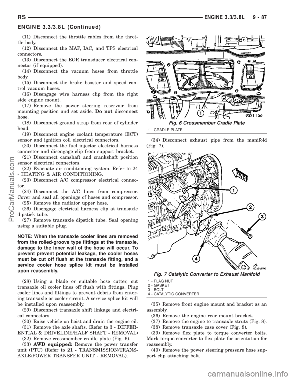
(32) Remove crossmember cradle plate (Fig. 6).
(33)AWD equipped:Remove the power transfer
unit (PTU) (Refer to 21 - TRANSMISSION/TRANS-
AXLE/POWER TRANSFER UNIT - REMOVAL).(34) Disconnect exhaust pipe from the manifold
(Fig. 7).
(35) Remove front engine mount and bracket as an
assembly.
(36) Remove the engine rear mount bracket.
(37) Remove the engine to transaxle struts (Fig. 8).
(38) Remove transaxle case cover (Fig. 8).
(39) Remove flex plate to torque converter bolts.
Mark torque converter to flex plate for orientation for
reassembly.
(40) Remove the power steering pressure hose sup-
port clip attaching bolt.
Fig. 6 Crossmember Cradle Plate
1 - CRADLE PLATE
Fig. 7 Catalytic Converter to Exhaust Manifold
1 - FLAG NUT
2 - GASKET
3 - BOLT
4 - CATALYTIC CONVERTER
RSENGINE 3.3/3.8L9-87
ENGINE 3.3/3.8L (Continued)
ProCarManuals.com
Page 1269 of 2177

(8) Install the generator and wiring harness (Refer
to 8 - ELECTRICAL/CHARGING/GENERATOR -
INSTALLATION).
(9) Raise vehicle.
(10) Attach wiring harness support clip to the
engine oil dipstick tube.
(11) Connect oil pressure switch electrical connec-
tor.
(12) Install the A/C compressor.
(13) Install the water pump pulley.
(14) Connect the radiator lower hose.(15) Install the accessory drive belt and splash
shield (Refer to 7 - COOLING/ACCESSORY DRIVE/
DRIVE BELTS - INSTALLATION).
(16) Connect the engine block heater electrical con-
nector (if equipped).
(17) Connect the knock sensor electrical connector
(3.8L only).
(18) Install the torque converter to flex plate bolts.
(19) Install the transaxle case cover (Fig. 8).
(20) Install the powertrain struts (Fig. 8).
(21) Install the engine rear mount bracket.
(22) Install the engine front mount and bracket
assembly.
(23)AWD equipped;Install the power transfer
unit (PTU) (Refer to 21 - TRANSMISSION/TRANS-
AXLE/POWER TRANSFER UNIT - INSTALLA-
TION).
(24) Install the axle shafts (Refer to 3 - DIFFER-
ENTIAL & DRIVELINE/HALF SHAFT - INSTALLA-
TION).
(25) Connect exhaust pipe to manifold (Fig. 7).
(26) Install crossmember cradle plate (Fig. 6).
(27) Lower vehicle.
(28) Connect transaxle shift linkage.
(29) Connect transaxle electrical connectors.
(30) Remove plugs from transmission cooler hoses
and install transaxle oil cooler line service splice kit.
Refer to instructions included with kit.
(31) Install transaxle dipstick tube and attach
electrical harness clip.
(32) Connect the A/C lines to compressor.
(33) Connect the A/C compressor electrical connec-
tor.
(34) Evacuate and recharge A/C system.
(35) Connect crankshaft and camshaft position
sensors.
(36) Connect the fuel injector electrical harness
connector and engage clip to support bracket.
(37) Connect engine coolant temperature (ECT)
sensor and ignition coil electrical connectors.
(38) Connect the ground strap to rear of cylinder
head.
(39) Install power steering reservoir.
(40) Engage wire harness clip to engine right side
mount.
(41) Connect the brake booster and speed control
vacuum hoses.
(42) Connect the vacuum hoses to the throttle
body.
(43) Connect the EGR transducer electrical connec-
tor (if equipped).
(44) Connect the TPS, IAC, and MAP sensor elec-
trical connectors.
(45) Connect throttle cables to throttle body.
(46) Install the radiator fans (Refer to 7 - COOL-
ING/ENGINE/RADIATOR FAN - INSTALLATION).
Fig. 13 Right Mount to Engine
1 - BOLT
2 - MOUNT BRACKET
3 - ENGINE RIGHT MOUNT ASSEMBLY
Fig. 14 LEFT MOUNT TO FRAME BRACKET
1 - FRAME BRACKET
2 - FRAME RAIL - LEFT
3 - BOLT
4 - TRANSAXLE MOUNT
9 - 90 ENGINE 3.3/3.8LRS
ENGINE 3.3/3.8L (Continued)
ProCarManuals.com
Page 1315 of 2177

LUBRICATION
DESCRIPTION
The lubrication system is a full flow filtration pres-
sure feed type. The oil pump is mounted in the tim-
ing chain cover and is driven by the crankshaft
OPERATION
Oil from the oil pan is pumped by a internal gear
type oil pump directly coupled to the crankshaft. The
pressure is regulated by a relief valve located in the
timing chain cover. The oil is pumped through an oil
filter and feeds a main oil gallery. This oil gallery
feeds oil under pressure to the main and rod bear-
ings, camshaft bearings. Passages in the cylinder
block feed oil to the hydraulic lifters and rocker shaft
brackets which feeds the rocker arm pivots (Fig. 94).
DIAGNOSIS AND TESTING - ENGINE OIL
PRESSURE
(1) Disconnect and remove oil pressure switch
(Refer to 9 - ENGINE/LUBRICATION/OIL PRES-
SURE SENSOR/SWITCH - REMOVAL).
(2) Install Special Tools C-3292 Gauge with 8406
Adaptor. For Special Tool identification, (Refer to 9 -
ENGINE - SPECIAL TOOLS).
(3) Start engine and record oil pressure. Refer to
Oil Pressure in Engine Specifications for the correct
pressure (Refer to 9 - ENGINE - SPECIFICATIONS).
Fig. 94 Engine Oiling System
1 - OIL SUPPLY FOR BALL SOCKET THROUGH PUSH ROD 7 - OUTER ROTOR
2 - OIL SUPPLY PASSAGE FROM SHAFT TO ROCKER ARM 8 - INNER ROTOR
3 - ROCKER SHAFT 9 - RELIEF VALVE
4 - OIL FLOWS TO ONLY ONE PEDASTAL ON EACH HEAD; THIRD
FROM REAR ON RIGHT HEAD, THIRD FROM FRONT ON LEFT
HEAD10 - OIL PAN
5 - ROCKER SHAFT TOWER 11 - OIL SCREEN
6 - CRANKSHAFT 12 - OIL PUMP CASE
9 - 136 ENGINE 3.3/3.8LRS
ProCarManuals.com
Page 1333 of 2177
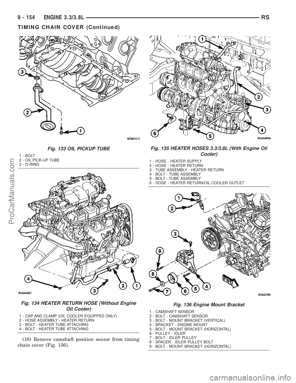
(16) Remove camshaft position sensor from timing
chain cover (Fig. 136).
Fig. 133 OIL PICKUP TUBE
1 - BOLT
2 - OIL PICK-UP TUBE
3 - O-RING
Fig. 134 HEATER RETURN HOSE (Without Engine
Oil Cooler)
1 - CAP AND CLAMP (OIL COOLER EQUIPPED ONLY)
2 - HOSE ASSEMBLY - HEATER RETURN
3 - BOLT - HEATER TUBE ATTACHING
4 - BOLT - HEATER TUBE ATTACHING
Fig. 135 HEATER HOSES 3.3/3.8L (With Engine Oil
Cooler)
1 - HOSE - HEATER SUPPLY
2 - HOSE - HEATER RETURN
3 - TUBE ASSEMBLY - HEATER RETURN
4 - BOLT - TUBE ASSEMBLY
5 - BOLT - TUBE ASSEMBLY
6 - HOSE - HEATER RETURN/OIL COOLER OUTLET
Fig. 136 Engine Mount Bracket
1 - CAMSHAFT SENSOR
2 - BOLT - CAMSHAFT SENSOR
3 - BOLT - MOUNT BRACKET (VERTICAL)
4 - BRACKET - ENGINE MOUNT
5 - BOLT - MOUNT BRACKET (HORIZONTAL)
6 - PULLEY - IDLER
7 - BOLT - IDLER PULLEY
8 - SPACER - IDLER PULLEY BOLT
9 - BOLT - MOUNT BRACKET (HORIZONTAL)
9 - 154 ENGINE 3.3/3.8LRS
TIMING CHAIN COVER (Continued)
ProCarManuals.com
Page 1334 of 2177
(17) Remove the water pump for cover removal
clearance. (Refer to 7 - COOLING/ENGINE/WATER
PUMP - REMOVAL)
(18) Remove the bolt attaching the power steering
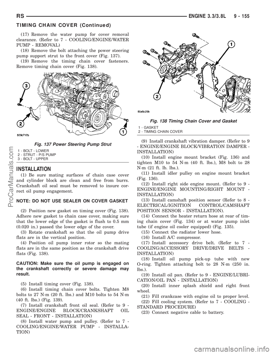
pump support strut to the front cover (Fig. 137).
(19) Remove the timing chain cover fasteners.
Remove timing chain cover (Fig. 138).
INSTALLATION
(1) Be sure mating surfaces of chain case cover
and cylinder block are clean and free from burrs.
Crankshaft oil seal must be removed to insure cor-
rect oil pump engagement.
NOTE: DO NOT USE SEALER ON COVER GASKET
(2) Position new gasket on timing cover (Fig. 138).
Adhere new gasket to chain case cover, making sure
that the lower edge of the gasket is flush to 0.5 mm
(0.020 in.) passed the lower edge of the cover.
(3) Rotate crankshaft so that the oil pump drive
flats are in the vertical position.
(4) Position oil pump inner rotor so the mating
flats are in the same position as the crankshaft drive
flats (Fig. 138).
CAUTION: Make sure the oil pump is engaged on
the crankshaft correctly or severe damage may
result.
(5) Install timing cover (Fig. 138).
(6) Install timing chain cover bolts. Tighten M8
bolts to 27 N´m (20 ft. lbs.) and M10 bolts to 54 N´m
(40 ft. lbs.) (Fig. 139).
(7) Install crankshaft front oil seal. (Refer to 9 -
ENGINE/ENGINE BLOCK/CRANKSHAFT OIL
SEAL - FRONT - INSTALLATION)
(8) Install water pump and pulley. (Refer to 7 -
COOLING/ENGINE/WATER PUMP - INSTALLA-
TION)(9) Install crankshaft vibration damper. (Refer to 9
- ENGINE/ENGINE BLOCK/VIBRATION DAMPER -
INSTALLATION)
(10) Install engine mount bracket (Fig. 136) and
tighten M10 to 54 N´m (40 ft. lbs.), M8 bolt to 28
N´m (21 ft. lb. lbs.).
(11) Install idler pulley on engine mount bracket
(Fig. 136).
(12) Install right side engine mount. (Refer to 9 -
ENGINE/ENGINE MOUNTING/RIGHT MOUNT -
INSTALLATION)
(13) Install camshaft position sensor (Refer to 8 -
ELECTRICAL/IGNITION CONTROL/CAMSHAFT
POSITION SENSOR - INSTALLATION).
(14) Connect the heater return hose at rear of tim-
ing chain cover (Fig. 134) or at water pump inlet
tube (if engine oil cooler equipped) (Fig. 135).
(15) Connect the radiator lower hose.
(16) Install A/C compressor.
(17) Install accessory drive belt. (Refer to 7 -
COOLING/ACCESSORY DRIVE/DRIVE BELTS -
INSTALLATION)
(18) Install oil pump pick-up tube with new
O-ring. Tighten attaching bolt to 28 N´m (250 in.
lbs.).
(19) Install oil pan. (Refer to 9 - ENGINE/LUBRI-
CATION/OIL PAN - INSTALLATION)
(20) Install inner splash shield and right front
wheel.
(21) Fill crankcase with engine oil to proper level.
(22) Fill cooling system. (Refer to 7 - COOLING -
STANDARD PROCEDURE)
(23) Connect negative cable to battery.
Fig. 137 Power Steering Pump Strut
1 - BOLT - LOWER
2 - STRUT - P/S PUMP
3 - BOLT - UPPER
Fig. 138 Timing Chain Cover and Gasket
1 - GASKET
2 - TIMING CHAIN COVER
RSENGINE 3.3/3.8L9 - 155
TIMING CHAIN COVER (Continued)
ProCarManuals.com
Page 1361 of 2177
FUEL DELIVERY
DESCRIPTION
DESCRIPTION
The front wheel drive car uses a plastic fuel tank
located rear center of the vehicle.
The Fuel Delivery System consists of: the following
items:
²Electric fuel pump module
²Fuel filter
²Tubes/lines/hoses
²Fuel injectors
The in-tank fuel pump module contains the fuel
pump. The pump is serviced as part of the fuel pump
module. Refer to Fuel Pump Module.
The fuel filter is replaceable only as part of the
fuel pump module.
DESCRIPTION - FFV REPLACEMENT PARTS
Many components in a Flexible Fuel Vehicle (FFV)
are designed to be compatible with ethanol. Always
be sure that the vehicle is serviced with correct etha-
nol compatible parts.
CAUTION: Replacing fuel system components with
non-ethanol compatible components can damage
your vehicle and may void the warranty.
OPERATION
The fuel system provides fuel pressure by an
in-tank pump module. The PCM controls the opera-
tion of the fuel system by providing battery voltage
to the fuel pump through the fuel pump relay. The
PCM requires only three inputs and a good ground to
operate the fuel pump relay. The three inputs are:
²Ignition voltage
²Crankshaft Position (CKP) sensor
²Camshaft Position (CMP) sensor
DIAGNOSIS AND TESTING - FUEL DELIVERY
SYSTEM
(Refer to Appropriate Diagnostic Information)
STANDARD PROCEDURE
STANDARD PROCEDURE - FUEL SYSTEM
PRESSURE RELEASE PROCEDURE
(1) Remove Fuel Pump relay from Power Distribu-
tion Center (PDC). For location of relay, refer to label
on underside of PDC cover.
(2) Start and run engine until it stalls.(3) Attempt restarting engine until it will no
longer run.
(4) Turn ignition key to OFF position.
(5) Return fuel pump relay to PDC.
(6) One or more Diagnostic Trouble Codes (DTC's)
may have been stored in PCM memory due to fuel
pump relay removal. The DRB IIItscan tool must be
used to erase a DTC.
STANDARD PROCEDURE - DRAINING FUEL
TANK
Two different procedures may be used to drain fuel
tank (lowering tank or using DRB scan tool).
The quickest draining procedure involves lowering
the fuel tank.
WARNING: RELEASE FUEL SYSTEM PRESSURE
BEFORE SERVICING FUEL SYSTEM COMPONENTS.
SERVICE VEHICLES IN WELL VENTILATED AREAS
AND AVOID IGNITION SOURCES. NEVER SMOKE
WHILE SERVICING THE VEHICLE.
As an alternative procedure, the electric fuel pump
may be activated allowing tank to be drained at fuel
rail connection. Refer to DRBIIItscan tool for fuel
pump activation procedures. Before disconnecting
fuel line at fuel rail, release fuel pressure. Refer to
the Fuel System Pressure Release Procedure in this
group for procedures. Disconnect the fuel line at the
fuel rail and remove the plastic retainer from the
fuel rail. Take plastic retainer and install it back into
the fuel line from body. Attach end of special test
hose tool number 8978 at fuel line connection from
the body line. Position opposite end of this hose tool
to an approved gasoline draining station. Activate
fuel pump and drain tank until empty. When done
remove the special test hose tool number 8978 from
the body line. Remove the plastic retainer from the
special test hose tool number 8978 and reinstall it
into the fuel line from the body. Install the fuel line
to the fuel rail.
If electric fuel pump is not operating, tank must be
lowered for fuel draining. Refer to following proce-
dures.
(1) Remove fuel filler cap.
(2) Perform the Fuel System Pressure Release pro-
cedure.
(3) Disconnect negative cable from battery.
(4) Raise vehicle and support.
(5) Certain models are equipped with a separate
grounding wire (strap) connecting the fuel fill tube
assembly to the body. Disconnect wire by removing
screw.
(6) Open fuel fill door and remove screws mount-
ing fuel filler tube assembly to body. Do not discon-
14 - 2 FUEL DELIVERYRS
ProCarManuals.com
Page 1378 of 2177
1 second. Therefore, battery voltage is not supplied to
the fuel pump, ignition coil, fuel injectors and heated
oxygen sensors.
ENGINE START-UP MODE
This is an OPEN LOOP mode. If the vehicle is in
park or neutral (automatic transaxles) or the clutch
pedal is depressed (manual transaxles) the ignition
switch energizes the starter relay when the engine is
not running. The following actions occur when the
starter motor is engaged.
²If the PCM receives the camshaft position sensor
and crankshaft position sensor signals, it energizes
the Auto Shutdown (ASD) relay and fuel pump relay.
If the PCM does not receive both signals within
approximately one second, it will not energize the
ASD relay and fuel pump relay. The ASD and fuel
pump relays supply battery voltage to the fuel pump,
fuel injectors, ignition coil, (EGR solenoid and PCV
heater if equipped) and heated oxygen sensors.
²The PCM energizes the injectors (on the 69É
degree falling edge) for a calculated pulse width until
it determines crankshaft position from the camshaft
position sensor and crankshaft position sensor sig-
nals. The PCM determines crankshaft position within
1 engine revolution.
²After determining crankshaft position, the PCM
begins energizing the injectors in sequence. It adjusts
injector pulse width and controls injector synchroni-
zation by turning the individual ground paths to the
injectors On and Off.
²When the engine idles within 64 RPM of its
target RPM, the PCM compares current MAP sensor
value with the atmospheric pressure value received
during the Ignition Switch On (zero RPM) mode.
Once the ASD and fuel pump relays have been
energized, the PCM determines injector pulse width
based on the following:
²MAP
²Engine RPM
²Battery voltage
²Engine coolant temperature
²Inlet/Intake air temperature (IAT)
²Throttle position
²The number of engine revolutions since cranking
was initiated
During Start-up the PCM maintains ignition tim-
ing at 9É BTDC.
ENGINE WARM-UP MODE
This is an OPEN LOOP mode. The following inputs
are received by the PCM:
²Manifold Absolute Pressure (MAP)
²Crankshaft position (engine speed)
²Engine coolant temperature
²Inlet/Intake air temperature (IAT)²Camshaft position
²Knock sensor
²Throttle position
²A/C switch status
²Battery voltage
²Vehicle speed
²Speed control
²O2 sensors
The PCM adjusts injector pulse width and controls
injector synchronization by turning the individual
ground paths to the injectors On and Off.
The PCM adjusts ignition timing and engine idle
speed. Engine idle speed is adjusted through the idle
air control motor.
CRUISE OR IDLE MODE
When the engine is at operating temperature this
is a CLOSED LOOP mode. During cruising or idle
the following inputs are received by the PCM:
²Manifold absolute pressure
²Crankshaft position (engine speed)
²Inlet/Intake air temperature
²Engine coolant temperature
²Camshaft position
²Knock sensor
²Throttle position
²Exhaust gas oxygen content (O2 sensors)
²A/C switch status
²Battery voltage
²Vehicle speed
The PCM adjusts injector pulse width and controls
injector synchronization by turning the individual
ground paths to the injectors On and Off.
The PCM adjusts engine idle speed and ignition
timing. The PCM adjusts the air/fuel ratio according
to the oxygen content in the exhaust gas (measured
by the upstream and downstream heated oxygen sen-
sor).
The PCM monitors for engine misfire. During
active misfire and depending on the severity, the
PCM either continuously illuminates or flashes the
malfunction indicator lamp (Check Engine light on
instrument panel). Also, the PCM stores an engine
misfire DTC in memory, if 2nd trip with fault.
The PCM performs several diagnostic routines.
They include:
²Oxygen sensor monitor
²Downstream heated oxygen sensor diagnostics
during open loop operation (except for shorted)
²Fuel system monitor
²EGR monitor (if equipped)
²Purge system monitor
²Catalyst efficiency monitor
²All inputs monitored for proper voltage range,
rationality.
RSFUEL INJECTION14-19
FUEL INJECTION (Continued)
ProCarManuals.com