2003 CHRYSLER VOYAGER break
[x] Cancel search: breakPage 1082 of 2177
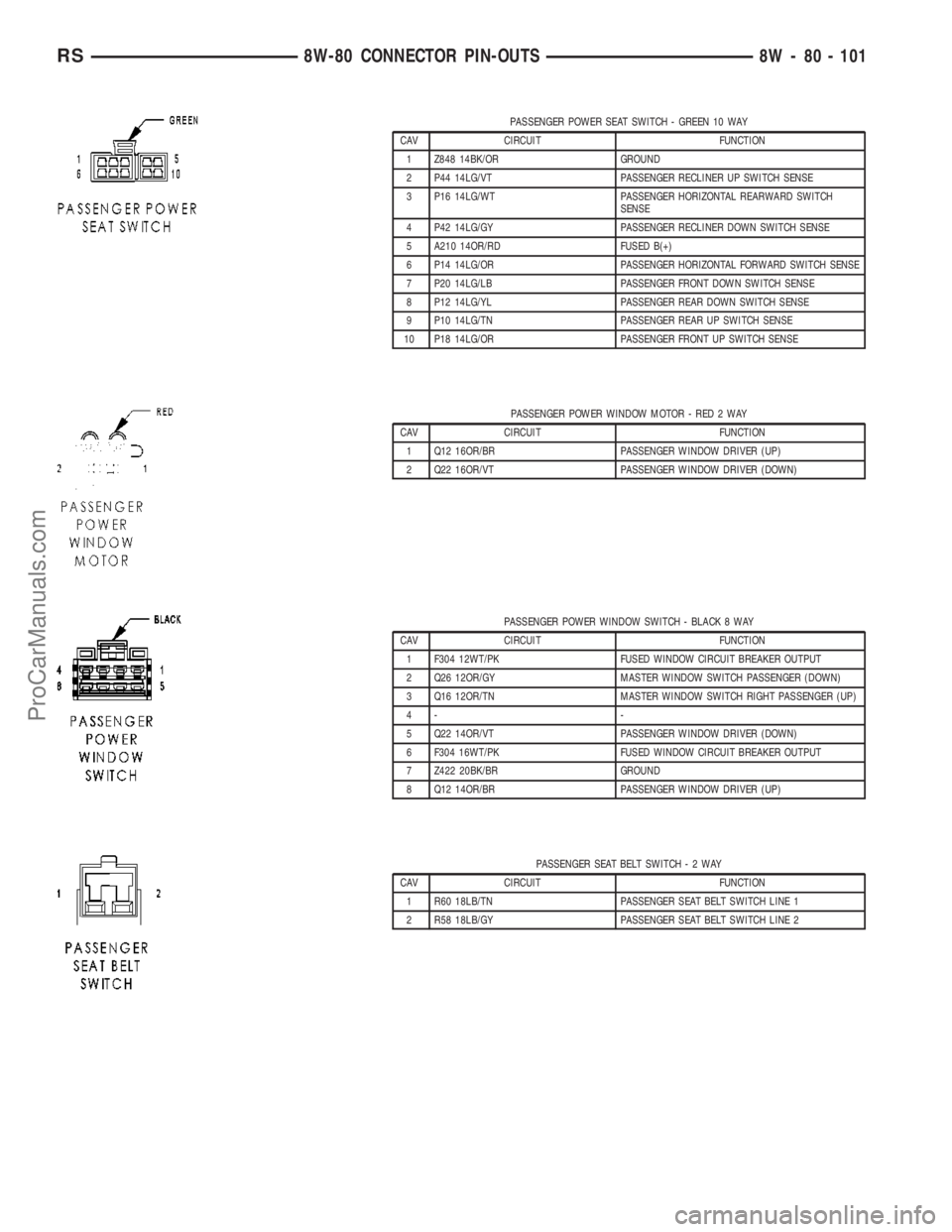
PASSENGER POWER SEAT SWITCH - GREEN 10 WAY
CAV CIRCUIT FUNCTION
1 Z848 14BK/OR GROUND
2 P44 14LG/VT PASSENGER RECLINER UP SWITCH SENSE
3 P16 14LG/WT PASSENGER HORIZONTAL REARWARD SWITCH
SENSE
4 P42 14LG/GY PASSENGER RECLINER DOWN SWITCH SENSE
5 A210 14OR/RD FUSED B(+)
6 P14 14LG/OR PASSENGER HORIZONTAL FORWARD SWITCH SENSE
7 P20 14LG/LB PASSENGER FRONT DOWN SWITCH SENSE
8 P12 14LG/YL PASSENGER REAR DOWN SWITCH SENSE
9 P10 14LG/TN PASSENGER REAR UP SWITCH SENSE
10 P18 14LG/OR PASSENGER FRONT UP SWITCH SENSE
PASSENGER POWER WINDOW MOTOR - RED 2 WAY
CAV CIRCUIT FUNCTION
1 Q12 16OR/BR PASSENGER WINDOW DRIVER (UP)
2 Q22 16OR/VT PASSENGER WINDOW DRIVER (DOWN)
PASSENGER POWER WINDOW SWITCH - BLACK 8 WAY
CAV CIRCUIT FUNCTION
1 F304 12WT/PK FUSED WINDOW CIRCUIT BREAKER OUTPUT
2 Q26 12OR/GY MASTER WINDOW SWITCH PASSENGER (DOWN)
3 Q16 12OR/TN MASTER WINDOW SWITCH RIGHT PASSENGER (UP)
4- -
5 Q22 14OR/VT PASSENGER WINDOW DRIVER (DOWN)
6 F304 16WT/PK FUSED WINDOW CIRCUIT BREAKER OUTPUT
7 Z422 20BK/BR GROUND
8 Q12 14OR/BR PASSENGER WINDOW DRIVER (UP)
PASSENGER SEAT BELT SWITCH-2WAY
CAV CIRCUIT FUNCTION
1 R60 18LB/TN PASSENGER SEAT BELT SWITCH LINE 1
2 R58 18LB/GY PASSENGER SEAT BELT SWITCH LINE 2
RS8W-80 CONNECTOR PIN-OUTS8W - 80 - 101
ProCarManuals.com
Page 1085 of 2177
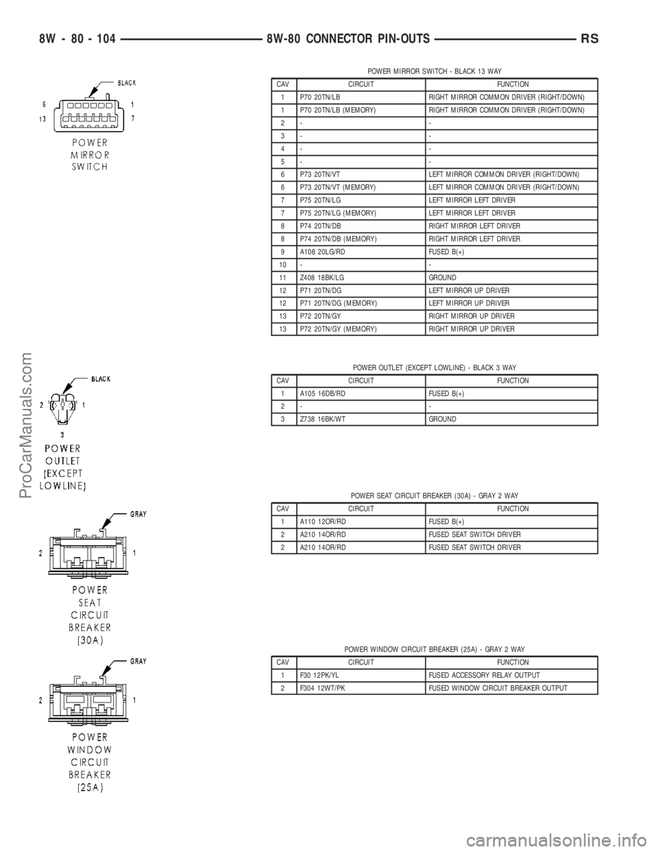
POWER MIRROR SWITCH - BLACK 13 WAY
CAV CIRCUIT FUNCTION
1 P70 20TN/LB RIGHT MIRROR COMMON DRIVER (RIGHT/DOWN)
1 P70 20TN/LB (MEMORY) RIGHT MIRROR COMMON DRIVER (RIGHT/DOWN)
2- -
3- -
4- -
5- -
6 P73 20TN/VT LEFT MIRROR COMMON DRIVER (RIGHT/DOWN)
6 P73 20TN/VT (MEMORY) LEFT MIRROR COMMON DRIVER (RIGHT/DOWN)
7 P75 20TN/LG LEFT MIRROR LEFT DRIVER
7 P75 20TN/LG (MEMORY) LEFT MIRROR LEFT DRIVER
8 P74 20TN/DB RIGHT MIRROR LEFT DRIVER
8 P74 20TN/DB (MEMORY) RIGHT MIRROR LEFT DRIVER
9 A108 20LG/RD FUSED B(+)
10 - -
11 Z408 18BK/LG GROUND
12 P71 20TN/DG LEFT MIRROR UP DRIVER
12 P71 20TN/DG (MEMORY) LEFT MIRROR UP DRIVER
13 P72 20TN/GY RIGHT MIRROR UP DRIVER
13 P72 20TN/GY (MEMORY) RIGHT MIRROR UP DRIVER
POWER OUTLET (EXCEPT LOWLINE) - BLACK 3 WAY
CAV CIRCUIT FUNCTION
1 A105 16DB/RD FUSED B(+)
2- -
3 Z738 16BK/WT GROUND
POWER SEAT CIRCUIT BREAKER (30A) - GRAY 2 WAY
CAV CIRCUIT FUNCTION
1 A110 12OR/RD FUSED B(+)
2 A210 14OR/RD FUSED SEAT SWITCH DRIVER
2 A210 14OR/RD FUSED SEAT SWITCH DRIVER
POWER WINDOW CIRCUIT BREAKER (25A) - GRAY 2 WAY
CAV CIRCUIT FUNCTION
1 F30 12PK/YL FUSED ACCESSORY RELAY OUTPUT
2 F304 12WT/PK FUSED WINDOW CIRCUIT BREAKER OUTPUT
8W - 80 - 104 8W-80 CONNECTOR PIN-OUTSRS
ProCarManuals.com
Page 1086 of 2177
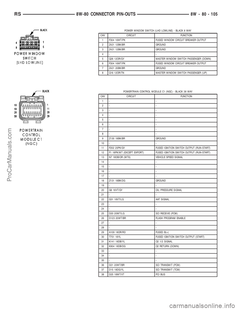
POWER WINDOW SWITCH (LHD LOWLINE) - BLACK 8 WAY
CAV CIRCUIT FUNCTION
1 F304 16WT/PK FUSED WINDOW CIRCUIT BREAKER OUTPUT
2 Z421 12BK/BR GROUND
3 Z421 12BK/BR GROUND
4- -
5 Q26 12OR/GY MASTER WINDOW SWITCH PASSENGER (DOWN)
6 F304 16WT/PK FUSED WINDOW CIRCUIT BREAKER OUTPUT
7 Z421 20BK/BR GROUND
8 Q16 12OR/TN MASTER WINDOW SWITCH PASSENGER (UP)
POWERTRAIN CONTROL MODULE C1 (NGC) - BLACK 38 WAY
CAV CIRCUIT FUNCTION
1- -
2- -
3- -
4- -
5- -
6- -
7- -
8- -
9 Z130 18BK/BR GROUND
10 - -
11 F202 20PK/GY FUSED IGNITION SWITCH OUTPUT (RUN-START)
12 F1 18PK/WT (EXCEPT EXPORT) FUSED IGNITION SWITCH OUTPUT (RUN-START)
13 N7 18DB/OR (MTX) VEHICLE SPEED SIGNAL
14 - -
15 - -
16 - -
17 - -
18 Z131 18BK/DG GROUND
19 - -
20 G6 16VT/GY OIL PRESSURE SIGNAL
21 - -
22 G31 18VT/LG AAT SIGNAL
23 - -
24 - -
25 D20 20WT/LG SCI RECEIVE (PCM)
26 D123 20WT/BR FLASH PROGRAM ENABLE
27 - -
28 - -
29 A109 18OR/RD FUSED B(+)
30 T751 18YL FUSED IGNITION SWITCH OUTPUT (START)
31 K141 18DB/YL O2 1/2 SIGNAL
32 K904 18DB/DG O2 RETURN (DOWN)
33 - -
34 - -
35 - -
36 D21 20WT/BR SCI TRANSMIT (PCM)
37 D15 18DG/YL SCI TRANSMIT (TCM)
38 D25 18WT/VT PCI BUS
RS8W-80 CONNECTOR PIN-OUTS8W - 80 - 105
ProCarManuals.com
Page 1124 of 2177
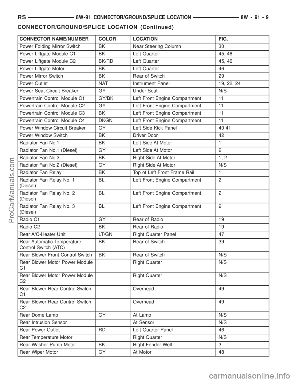
CONNECTOR NAME/NUMBER COLOR LOCATION FIG.
Power Folding Mirror Switch BK Near Steering Column 30
Power Liftgate Module C1 BK Left Quarter 45, 46
Power Liftgate Module C2 BK/RD Left Quarter 45, 46
Power Liftgate Motor BK Left Quarter 46
Power Mirror Switch BK Rear of Switch 29
Power Outlet NAT Instrument Panel 19, 22, 24
Power Seat Circuit Breaker GY Under Seat N/S
Powertrain Control Module C1 GY/BK Left Front Engine Compartment 11
Powertrain Control Module C2 GY Left Front Engine Compartment 11
Powertrain Control Module C3 BK Left Front Engine Compartment 11
Powertrain Control Module C4 DKGN Left Front Engine Compartment 11
Power Window Circuit Breaker GY Left Side Kick Panel 40 41
Power Window Switch BK Driver Door 42
Radiator Fan No.1 BK Left Side At Motor 1
Radiator Fan No.1 (Diesel) GY Left Side At Motor 2
Radiator Fan No.2 BK Right Side At Motor 1, 2
Radiator Fan No.2 (Diesel) GY Right Side At Motor N/S
Radiator Fan Relay BK Top of Left Front Frame Rail 1
Radiator Fan Relay No. 1
(Diesel)BL Left Front Engine Compartment 2
Radiator Fan Relay No. 2
(Diesel)BL Left Front Engine Compartment 2
Radiator Fan Relay No. 3
(Diesel)BL Left Front Engine Compartment 2
Radio C1 GY Rear of Radio 19
Radio C2 BK Rear of Radio 19
Rear A/C-Heater Unit LT/GN Right Quarter Panel 47
Rear Automatic Temperature
Control Switch (ATC)BK Rear of Switch 39
Rear Blower Front Control Switch BK Rear of Switch N/S
Rear Blower Motor Power Module
C1Right Quarter N/S
Rear Blower Motor Power Module
C2Right Quarter N/S
Rear Blower Rear Control Switch
C1Overhead 49
Rear Blower Rear Control Switch
C2Overhead 49
Rear Dome Lamp GY At Lamp N/S
Rear Intrusion Sensor At Sensor N/S
Rear Power Outlet RD Left Quarter Panel 46
Rear Temperature Motor Right Quarter N/S
Rear Washer Pump Motor BK Right Fender Well 3
Rear Wiper Motor GY At Motor 48
RS8W-91 CONNECTOR/GROUND/SPLICE LOCATION8W-91-9
CONNECTOR/GROUND/SPLICE LOCATION (Continued)
ProCarManuals.com
Page 1129 of 2177
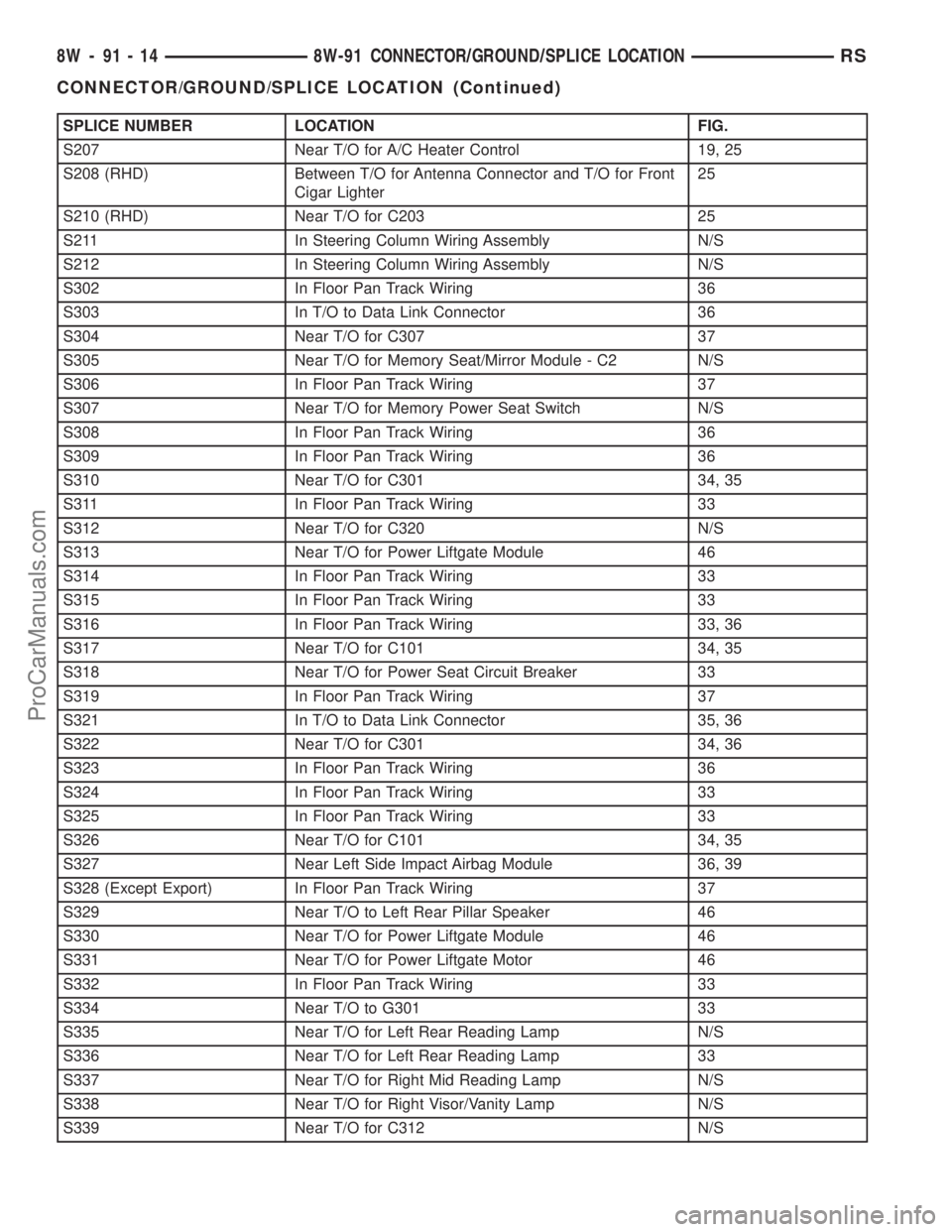
SPLICE NUMBER LOCATION FIG.
S207 Near T/O for A/C Heater Control 19, 25
S208 (RHD) Between T/O for Antenna Connector and T/O for Front
Cigar Lighter25
S210 (RHD) Near T/O for C203 25
S211 In Steering Column Wiring Assembly N/S
S212 In Steering Column Wiring Assembly N/S
S302 In Floor Pan Track Wiring 36
S303 In T/O to Data Link Connector 36
S304 Near T/O for C307 37
S305 Near T/O for Memory Seat/Mirror Module - C2 N/S
S306 In Floor Pan Track Wiring 37
S307 Near T/O for Memory Power Seat Switch N/S
S308 In Floor Pan Track Wiring 36
S309 In Floor Pan Track Wiring 36
S310 Near T/O for C301 34, 35
S311 In Floor Pan Track Wiring 33
S312 Near T/O for C320 N/S
S313 Near T/O for Power Liftgate Module 46
S314 In Floor Pan Track Wiring 33
S315 In Floor Pan Track Wiring 33
S316 In Floor Pan Track Wiring 33, 36
S317 Near T/O for C101 34, 35
S318 Near T/O for Power Seat Circuit Breaker 33
S319 In Floor Pan Track Wiring 37
S321 In T/O to Data Link Connector 35, 36
S322 Near T/O for C301 34, 36
S323 In Floor Pan Track Wiring 36
S324 In Floor Pan Track Wiring 33
S325 In Floor Pan Track Wiring 33
S326 Near T/O for C101 34, 35
S327 Near Left Side Impact Airbag Module 36, 39
S328 (Except Export) In Floor Pan Track Wiring 37
S329 Near T/O to Left Rear Pillar Speaker 46
S330 Near T/O for Power Liftgate Module 46
S331 Near T/O for Power Liftgate Motor 46
S332 In Floor Pan Track Wiring 33
S334 Near T/O to G301 33
S335 Near T/O for Left Rear Reading Lamp N/S
S336 Near T/O for Left Rear Reading Lamp 33
S337 Near T/O for Right Mid Reading Lamp N/S
S338 Near T/O for Right Visor/Vanity Lamp N/S
S339 Near T/O for C312 N/S
8W - 91 - 14 8W-91 CONNECTOR/GROUND/SPLICE LOCATIONRS
CONNECTOR/GROUND/SPLICE LOCATION (Continued)
ProCarManuals.com
Page 1174 of 2177
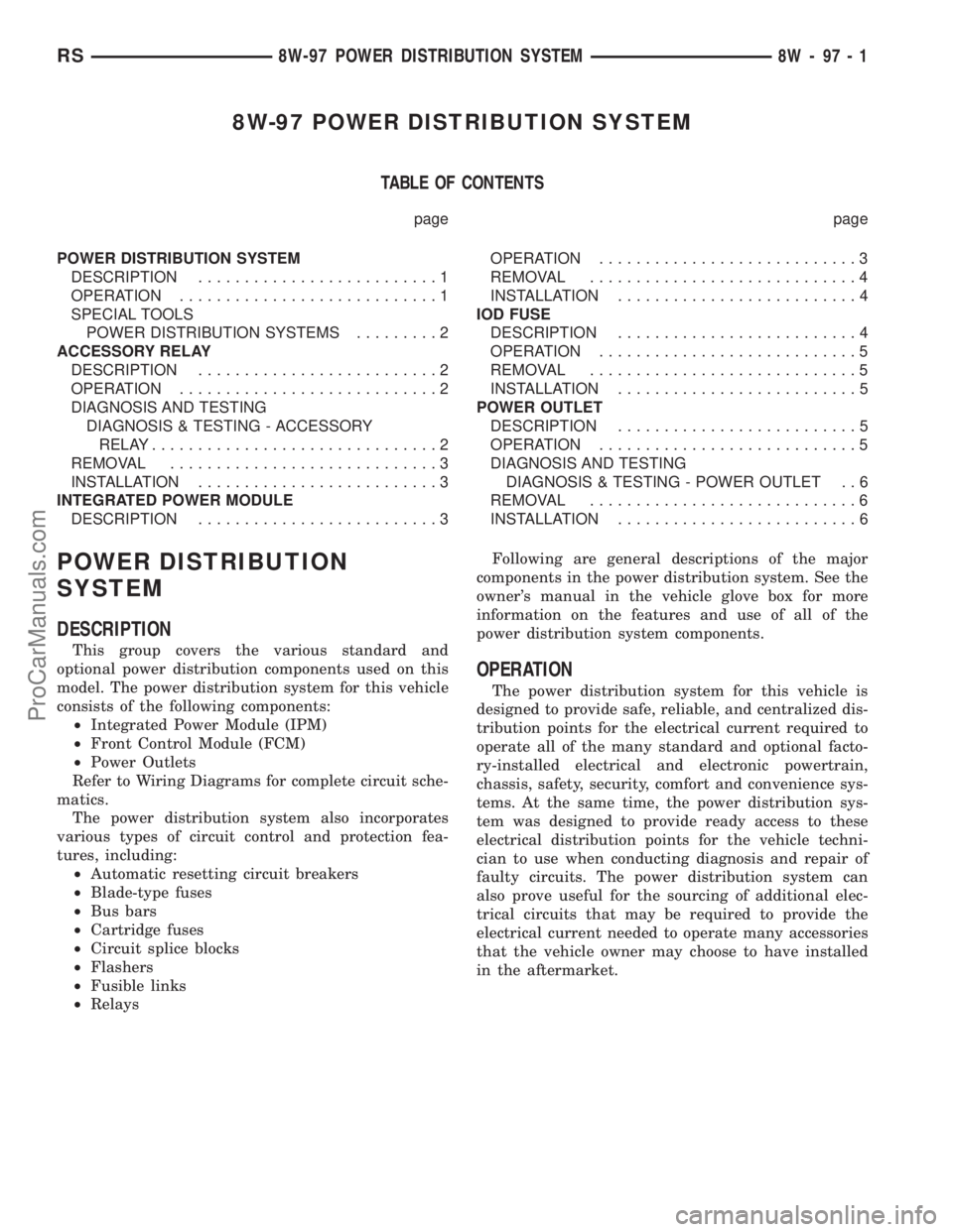
8W-97 POWER DISTRIBUTION SYSTEM
TABLE OF CONTENTS
page page
POWER DISTRIBUTION SYSTEM
DESCRIPTION..........................1
OPERATION............................1
SPECIAL TOOLS
POWER DISTRIBUTION SYSTEMS.........2
ACCESSORY RELAY
DESCRIPTION..........................2
OPERATION............................2
DIAGNOSIS AND TESTING
DIAGNOSIS & TESTING - ACCESSORY
RELAY...............................2
REMOVAL.............................3
INSTALLATION..........................3
INTEGRATED POWER MODULE
DESCRIPTION..........................3OPERATION............................3
REMOVAL.............................4
INSTALLATION..........................4
IOD FUSE
DESCRIPTION..........................4
OPERATION............................5
REMOVAL.............................5
INSTALLATION..........................5
POWER OUTLET
DESCRIPTION..........................5
OPERATION............................5
DIAGNOSIS AND TESTING
DIAGNOSIS & TESTING - POWER OUTLET . . 6
REMOVAL.............................6
INSTALLATION..........................6
POWER DISTRIBUTION
SYSTEM
DESCRIPTION
This group covers the various standard and
optional power distribution components used on this
model. The power distribution system for this vehicle
consists of the following components:
²Integrated Power Module (IPM)
²Front Control Module (FCM)
²Power Outlets
Refer to Wiring Diagrams for complete circuit sche-
matics.
The power distribution system also incorporates
various types of circuit control and protection fea-
tures, including:
²Automatic resetting circuit breakers
²Blade-type fuses
²Bus bars
²Cartridge fuses
²Circuit splice blocks
²Flashers
²Fusible links
²RelaysFollowing are general descriptions of the major
components in the power distribution system. See the
owner's manual in the vehicle glove box for more
information on the features and use of all of the
power distribution system components.
OPERATION
The power distribution system for this vehicle is
designed to provide safe, reliable, and centralized dis-
tribution points for the electrical current required to
operate all of the many standard and optional facto-
ry-installed electrical and electronic powertrain,
chassis, safety, security, comfort and convenience sys-
tems. At the same time, the power distribution sys-
tem was designed to provide ready access to these
electrical distribution points for the vehicle techni-
cian to use when conducting diagnosis and repair of
faulty circuits. The power distribution system can
also prove useful for the sourcing of additional elec-
trical circuits that may be required to provide the
electrical current needed to operate many accessories
that the vehicle owner may choose to have installed
in the aftermarket.
RS8W-97 POWER DISTRIBUTION SYSTEM8W-97-1
ProCarManuals.com
Page 1189 of 2177
Calibrate the tester according to the manufactur-
er's instructions. The shop air source for testing
should maintain 483 kPa (70 psi) minimum, 1,379
kPa (200 psi) maximum, with 552 kPa (80 psi) rec-
ommended.
Perform the test procedures on each cylinder
according to the tester manufacturer's instructions.
While testing, listen for pressurized air escaping
through the throttle body, tailpipe and oil filler cap
opening. Check for bubbles in the coolant.
All gauge pressure indications should be equal,
with no more than 25% leakage per cylinder.
FOR EXAMPLE:At 552 kPa (80 psi) input pres-
sure, a minimum of 414 kPa (60 psi) should be main-
tained in the cylinder.
STANDARD PROCEDURE
STANDARD PROCEDURE - ENGINE CORE AND
OIL GALLERY PLUGS
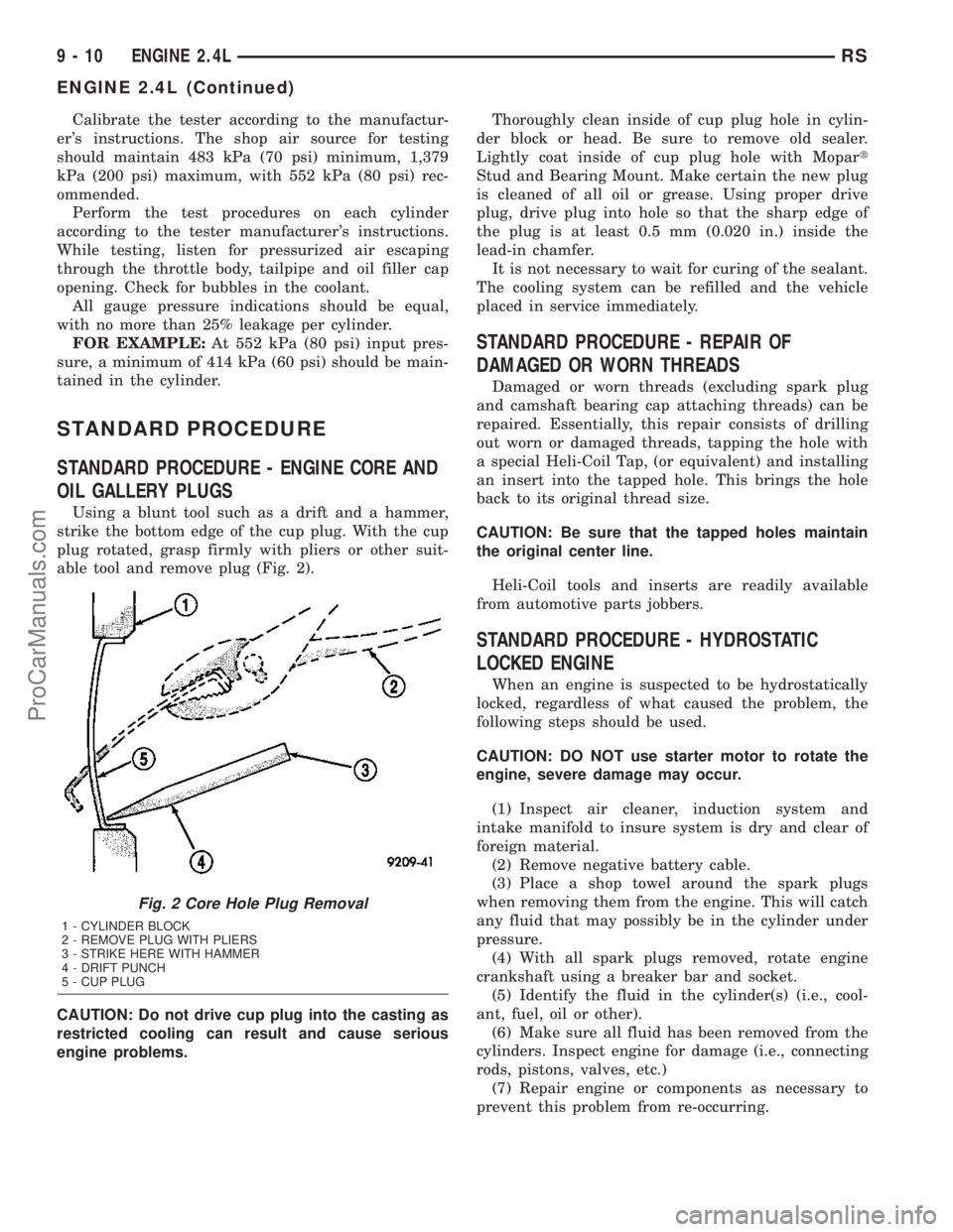
Using a blunt tool such as a drift and a hammer,
strike the bottom edge of the cup plug. With the cup
plug rotated, grasp firmly with pliers or other suit-
able tool and remove plug (Fig. 2).
CAUTION: Do not drive cup plug into the casting as
restricted cooling can result and cause serious
engine problems.Thoroughly clean inside of cup plug hole in cylin-
der block or head. Be sure to remove old sealer.
Lightly coat inside of cup plug hole with Mopart
Stud and Bearing Mount. Make certain the new plug
is cleaned of all oil or grease. Using proper drive
plug, drive plug into hole so that the sharp edge of
the plug is at least 0.5 mm (0.020 in.) inside the
lead-in chamfer.
It is not necessary to wait for curing of the sealant.
The cooling system can be refilled and the vehicle
placed in service immediately.
STANDARD PROCEDURE - REPAIR OF
DAMAGED OR WORN THREADS
Damaged or worn threads (excluding spark plug
and camshaft bearing cap attaching threads) can be
repaired. Essentially, this repair consists of drilling
out worn or damaged threads, tapping the hole with
a special Heli-Coil Tap, (or equivalent) and installing
an insert into the tapped hole. This brings the hole
back to its original thread size.
CAUTION: Be sure that the tapped holes maintain
the original center line.
Heli-Coil tools and inserts are readily available
from automotive parts jobbers.
STANDARD PROCEDURE - HYDROSTATIC
LOCKED ENGINE
When an engine is suspected to be hydrostatically
locked, regardless of what caused the problem, the
following steps should be used.
CAUTION: DO NOT use starter motor to rotate the
engine, severe damage may occur.
(1) Inspect air cleaner, induction system and
intake manifold to insure system is dry and clear of
foreign material.
(2) Remove negative battery cable.
(3) Place a shop towel around the spark plugs
when removing them from the engine. This will catch
any fluid that may possibly be in the cylinder under
pressure.
(4) With all spark plugs removed, rotate engine
crankshaft using a breaker bar and socket.
(5) Identify the fluid in the cylinder(s) (i.e., cool-
ant, fuel, oil or other).
(6) Make sure all fluid has been removed from the
cylinders. Inspect engine for damage (i.e., connecting
rods, pistons, valves, etc.)
(7) Repair engine or components as necessary to
prevent this problem from re-occurring.
Fig. 2 Core Hole Plug Removal
1 - CYLINDER BLOCK
2 - REMOVE PLUG WITH PLIERS
3 - STRIKE HERE WITH HAMMER
4 - DRIFT PUNCH
5 - CUP PLUG
9 - 10 ENGINE 2.4LRS
ENGINE 2.4L (Continued)
ProCarManuals.com
Page 1190 of 2177
CAUTION: Squirt approximately one teaspoon of oil
into the cylinders, rotate engine to lubricate the cyl-
inder walls to prevent damage on restart.
(8) Install new spark plugs.
(9) Drain engine oil and remove oil filter.
(10) Install a new oil filter.
(11) Fill engine with specified amount of approved
oil.
(12) Connect negative battery cable.
(13) Start engine and check for any leaks.
STANDARD PROCEDURE - FORM-IN-PLACE
GASKETS AND SEALERS
There are numerous places where form-in-place
gaskets are used on the engine. Care must be taken
when applying form-in-place gaskets to assure
obtaining the desired results.Do not use form-in-
place gasket material unless specified.Bead size,
continuity, and location are of great importance. Too
thin a bead can result in leakage while too much can
result in spill-over which can break off and obstruct
fluid feed lines. A continuous bead of the proper
width is essential to obtain a leak-free gasket.
There are numerous types of form-in-place gasket
materials that are used in the engine area. Mopart
Engine RTV GEN II, MopartATF-RTV, and Mopart
Gasket Maker gasket materials, each have different
properties and can not be used in place of the other.
MOPARtENGINE RTV GEN IIis used to seal
components exposed to engine oil. This material is a
specially designed black silicone rubber RTV that
retains adhesion and sealing properties when
exposed to engine oil. Moisture in the air causes the
material to cure. This material is available in three
ounce tubes and has a shelf life of one year. After one
year this material will not properly cure. Always
inspect the package for the expiration date before
use.
MOPARtATF RTVis a specifically designed
black silicone rubber RTV that retains adhesion and
sealing properties to seal components exposed to
automatic transmission fluid, engine coolants, and
moisture. This material is available in three ounce
tubes and has a shelf life of one year. After one year
this material will not properly cure. Always inspect
the package for the expiration date before use.
MOPARtGASKET MAKERis an anaerobic type
gasket material. The material cures in the absence of
air when squeezed between two metallic surfaces. It
will not cure if left in the uncovered tube. The
anaerobic material is for use between two machined
surfaces. Do not use on flexible metal flanges.
MOPARtBED PLATE SEALANTis a unique
(green-in-color) anaerobic type gasket material that
is specially made to seal the area between the bed-plate and cylinder block without disturbing the bear-
ing clearance or alignment of these components. The
material cures slowly in the absence of air when
torqued between two metallic surfaces, and will rap-
idly cure when heat is applied.
MOPARtGASKET SEALANTis a slow drying,
permanently soft sealer. This material is recom-
mended for sealing threaded fittings and gaskets
against leakage of oil and coolant. Can be used on
threaded and machined parts under all tempera-
tures. This material is used on engines with multi-
layer steel (MLS) cylinder head gaskets. This
material also will prevent corrosion. MopartGasket
Sealant is available in a 13 oz. aerosol can or 4oz./16
oz. can w/applicator.
SEALER APPLICATION
MopartGasket Maker material should be applied
sparingly 1 mm (0.040 in.) diameter or less of sealant
to one gasket surface. Be certain the material sur-
rounds each mounting hole. Excess material can eas-
ily be wiped off. Components should be torqued in
place within 15 minutes. The use of a locating dowel
is recommended during assembly to prevent smear-
ing material off the location.
MopartEngine RTV GEN II or ATF RTV gasket
material should be applied in a continuous bead
approximately 3 mm (0.120 in.) in diameter. All
mounting holes must be circled. For corner sealing, a
3.17 or 6.35 mm (1/8 or 1/4 in.) drop is placed in the
center of the gasket contact area. Uncured sealant
may be removed with a shop towel. Components
should be torqued in place while the sealant is still
wet to the touch (within 10 minutes). The usage of a
locating dowel is recommended during assembly to
prevent smearing material off the location.
MopartGasket Sealant in an aerosol can should be
applied using a thin, even coat sprayed completely
over both surfaces to be joined, and both sides of a
gasket. Then proceed with assembly. Material in a
can w/applicator can be brushed on evenly over the
sealing surfaces. Material in an aerosol can should be
used on engines with multi-layer steel gaskets.
STANDARD PROCEDURE - ENGINE GASKET
SURFACE PREPARATION
To ensure engine gasket sealing, proper surface
preparation must be performed, especially with the
use of aluminum engine components and multi-layer
steel cylinder head gaskets.
Neveruse the following to clean gasket surfaces:
²Metal scraper
²Abrasive pad or paper to clean cylinder block
and head
²High speed power tool with an abrasive pad or a
wire brush (Fig. 3)
RSENGINE 2.4L9-11
ENGINE 2.4L (Continued)
ProCarManuals.com