2003 CHRYSLER VOYAGER Low fuel light
[x] Cancel search: Low fuel lightPage 1120 of 2177
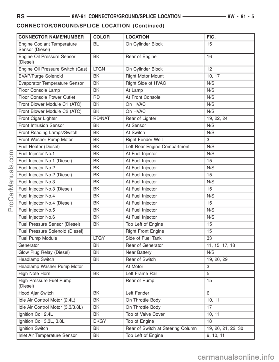
CONNECTOR NAME/NUMBER COLOR LOCATION FIG.
Engine Coolant Temperature
Sensor (Diesel)BL On Cylinder Block 15
Engine Oil Pressure Sensor
(Diesel)BK Rear of Engine 16
Engine Oil Pressure Switch (Gas) LTGN On Cylinder Block 12
EVAP/Purge Solenoid BK Right Motor Mount 10, 17
Evaporator Temperature Sensor BK Right Side of HVAC N/S
Floor Console Lamp BK At Lamp N/S
Floor Console Power Outlet RD At Front Console N/S
Front Blower Module C1 (ATC) BK On HVAC N/S
Front Blower Module C2 (ATC) BK On HVAC N/S
Front Cigar Lighter RD/NAT Rear of Lighter 19, 22, 24
Front Intrusion Sensor BK At Sensor N/S
Front Reading Lamps/Switch BK At Switch N/S
Front Washer Pump Motor BK Right Fender Well 3
Fuel Heater (Diesel) BK Left Rear Engine Compartment N/S
Fuel Injector No.1 BK At Fuel Injector N/S
Fuel Injector No.1 (Diesel) BK At Fuel Injector 15
Fuel Injector No.2 BK At Fuel Injector N/S
Fuel Injector No.2 (Diesel) BK At Fuel Injector 15
Fuel Injector No.3 BK At Fuel Injector N/S
Fuel Injector No.3 (Diesel) BK At Fuel Injector 15
Fuel Injector No.4 BK At Fuel Injector N/S
Fuel Injector No.4 (Diesel) BK At Fuel Injector 15
Fuel Injector No.5 BK At Fuel Injector N/S
Fuel Injector No.6 BK At Fuel Injector N/S
Fuel Pressure Sensor (Diesel) BK Top Left of Engine 15
Fuel Pressure Solenoid (Diesel) Right Front Engine 15
Fuel Pump Module LTGY Side of Fuel Tank 33
Generator BK Rear of Generator 11, 15, 17, 18
Glow Plug Relay (Diesel) BK Near Battery N/S
Headlamp Switch BK Rear of Switch 19, 20, 29
Headlamp Washer Pump Motor At Motor 3
High Note Horn BK Left Frame Rail 5
High Pressure Fuel Pump
(Diesel)Rear of Pump 15
Hood Ajar Switch BK Left Fender 6
Idle Air Control Motor (2.4L) BK On Throttle Body 10, 11
Idle Air Control Motor (3.3/3.8L) BK On Throttle Body 17
Ignition Coil 2.4L BK Top of Valve Cover 10, 11
Ignition Coil 3.3L, 3.8L DKGY Top of Engine 18
Ignition Switch BK Rear of Switch at Steering Column 19, 20, 21, 22, 30
Inlet Air Temperature Sensor BK Top Left of Engine 9, 10, 11
RS8W-91 CONNECTOR/GROUND/SPLICE LOCATION8W-91-5
CONNECTOR/GROUND/SPLICE LOCATION (Continued)
ProCarManuals.com
Page 1183 of 2177
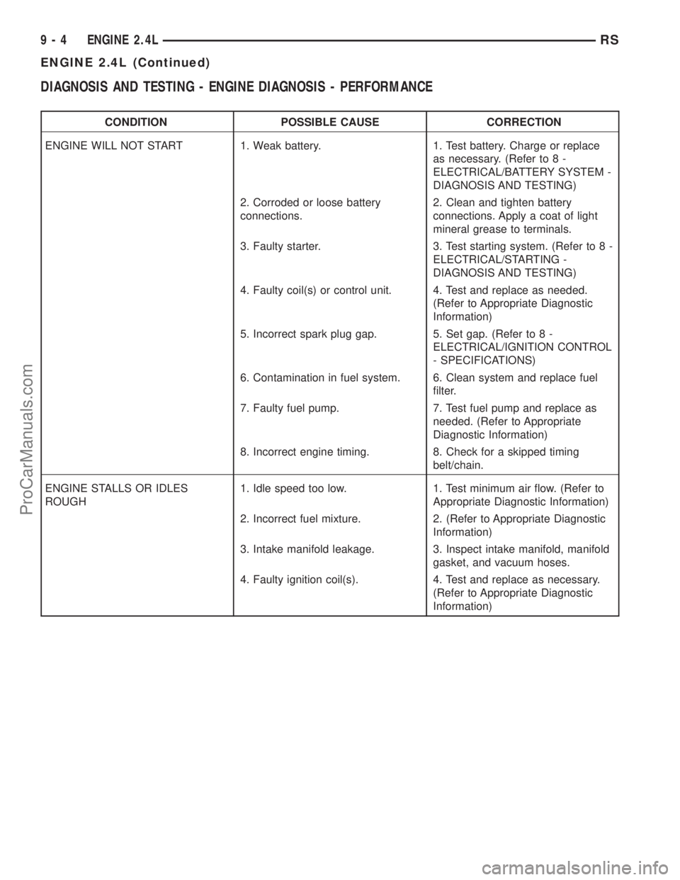
DIAGNOSIS AND TESTING - ENGINE DIAGNOSIS - PERFORMANCE
CONDITION POSSIBLE CAUSE CORRECTION
ENGINE WILL NOT START 1. Weak battery. 1. Test battery. Charge or replace
as necessary. (Refer to 8 -
ELECTRICAL/BATTERY SYSTEM -
DIAGNOSIS AND TESTING)
2. Corroded or loose battery
connections.2. Clean and tighten battery
connections. Apply a coat of light
mineral grease to terminals.
3. Faulty starter. 3. Test starting system. (Refer to 8 -
ELECTRICAL/STARTING -
DIAGNOSIS AND TESTING)
4. Faulty coil(s) or control unit. 4. Test and replace as needed.
(Refer to Appropriate Diagnostic
Information)
5. Incorrect spark plug gap. 5. Set gap. (Refer to 8 -
ELECTRICAL/IGNITION CONTROL
- SPECIFICATIONS)
6. Contamination in fuel system. 6. Clean system and replace fuel
filter.
7. Faulty fuel pump. 7. Test fuel pump and replace as
needed. (Refer to Appropriate
Diagnostic Information)
8. Incorrect engine timing. 8. Check for a skipped timing
belt/chain.
ENGINE STALLS OR IDLES
ROUGH1. Idle speed too low. 1. Test minimum air flow. (Refer to
Appropriate Diagnostic Information)
2. Incorrect fuel mixture. 2. (Refer to Appropriate Diagnostic
Information)
3. Intake manifold leakage. 3. Inspect intake manifold, manifold
gasket, and vacuum hoses.
4. Faulty ignition coil(s). 4. Test and replace as necessary.
(Refer to Appropriate Diagnostic
Information)
9 - 4 ENGINE 2.4LRS
ENGINE 2.4L (Continued)
ProCarManuals.com
Page 1189 of 2177
Calibrate the tester according to the manufactur-
er's instructions. The shop air source for testing
should maintain 483 kPa (70 psi) minimum, 1,379
kPa (200 psi) maximum, with 552 kPa (80 psi) rec-
ommended.
Perform the test procedures on each cylinder
according to the tester manufacturer's instructions.
While testing, listen for pressurized air escaping
through the throttle body, tailpipe and oil filler cap
opening. Check for bubbles in the coolant.
All gauge pressure indications should be equal,
with no more than 25% leakage per cylinder.
FOR EXAMPLE:At 552 kPa (80 psi) input pres-
sure, a minimum of 414 kPa (60 psi) should be main-
tained in the cylinder.
STANDARD PROCEDURE
STANDARD PROCEDURE - ENGINE CORE AND
OIL GALLERY PLUGS
Using a blunt tool such as a drift and a hammer,
strike the bottom edge of the cup plug. With the cup
plug rotated, grasp firmly with pliers or other suit-
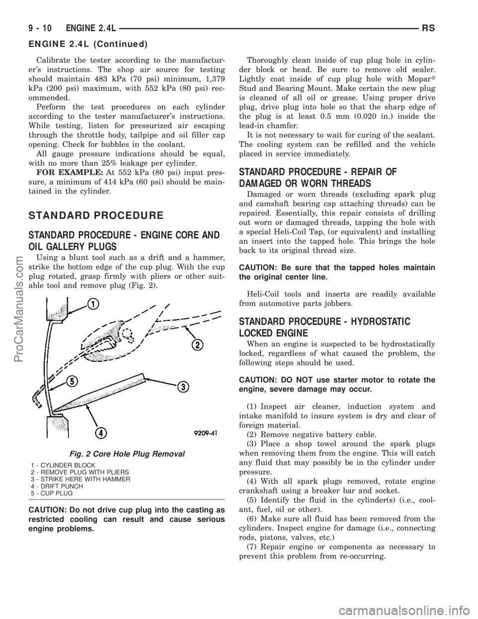
able tool and remove plug (Fig. 2).
CAUTION: Do not drive cup plug into the casting as
restricted cooling can result and cause serious
engine problems.Thoroughly clean inside of cup plug hole in cylin-
der block or head. Be sure to remove old sealer.
Lightly coat inside of cup plug hole with Mopart
Stud and Bearing Mount. Make certain the new plug
is cleaned of all oil or grease. Using proper drive
plug, drive plug into hole so that the sharp edge of
the plug is at least 0.5 mm (0.020 in.) inside the
lead-in chamfer.
It is not necessary to wait for curing of the sealant.
The cooling system can be refilled and the vehicle
placed in service immediately.
STANDARD PROCEDURE - REPAIR OF
DAMAGED OR WORN THREADS
Damaged or worn threads (excluding spark plug
and camshaft bearing cap attaching threads) can be
repaired. Essentially, this repair consists of drilling
out worn or damaged threads, tapping the hole with
a special Heli-Coil Tap, (or equivalent) and installing
an insert into the tapped hole. This brings the hole
back to its original thread size.
CAUTION: Be sure that the tapped holes maintain
the original center line.
Heli-Coil tools and inserts are readily available
from automotive parts jobbers.
STANDARD PROCEDURE - HYDROSTATIC
LOCKED ENGINE
When an engine is suspected to be hydrostatically
locked, regardless of what caused the problem, the
following steps should be used.
CAUTION: DO NOT use starter motor to rotate the
engine, severe damage may occur.
(1) Inspect air cleaner, induction system and
intake manifold to insure system is dry and clear of
foreign material.
(2) Remove negative battery cable.
(3) Place a shop towel around the spark plugs
when removing them from the engine. This will catch
any fluid that may possibly be in the cylinder under
pressure.
(4) With all spark plugs removed, rotate engine
crankshaft using a breaker bar and socket.
(5) Identify the fluid in the cylinder(s) (i.e., cool-
ant, fuel, oil or other).
(6) Make sure all fluid has been removed from the
cylinders. Inspect engine for damage (i.e., connecting
rods, pistons, valves, etc.)
(7) Repair engine or components as necessary to
prevent this problem from re-occurring.
Fig. 2 Core Hole Plug Removal
1 - CYLINDER BLOCK
2 - REMOVE PLUG WITH PLIERS
3 - STRIKE HERE WITH HAMMER
4 - DRIFT PUNCH
5 - CUP PLUG
9 - 10 ENGINE 2.4LRS
ENGINE 2.4L (Continued)
ProCarManuals.com
Page 1257 of 2177

DIAGNOSIS AND TESTING - ENGINE DIAGNOSIS - PERFORMANCE
CONDITION POSSIBLE CAUSE CORRECTION
ENGINE WILL NOT START 1. Weak battery. 1. Test battery. Charge or replace
as necessary. (Refer to 8 -
ELECTRICAL/BATTERY SYSTEM -
DIAGNOSIS AND TESTING)
2. Corroded or loose battery
connections.2. Clean and tighten battery
connections. Apply a coat of light
mineral grease to terminals.
3. Faulty starter. 3. Test starting system. (Refer to 8 -
ELECTRICAL/STARTING -
DIAGNOSIS AND TESTING)
4. Faulty coil(s) or control unit. 4. Test and replace as needed.
(Refer to Appropriate Diagnostic
Information)
5. Incorrect spark plug gap. 5. Set gap. (Refer to 8 -
ELECTRICAL/IGNITION CONTROL
- SPECIFICATIONS)
6. Contamination in fuel system. 6. Clean system and replace fuel
filter.
7. Faulty fuel pump. 7. Test fuel pump and replace as
needed. (Refer to Appropriate
Diagnostic Information)
8. Incorrect engine timing. 8. Check for a skipped timing
belt/chain.
ENGINE STALLS OR IDLES
ROUGH1. Idle speed too low. 1. Test minimum air flow. (Refer to
Appropriate Diagnostic Information)
2. Incorrect fuel mixture. 2. (Refer to Appropriate Diagnostic
Information)
3. Intake manifold leakage. 3. Inspect intake manifold, manifold
gasket, and vacuum hoses.
4. Faulty ignition coil(s). 4. Test and replace as necessary.
(Refer to Appropriate Diagnostic
Information)
9 - 78 ENGINE 3.3/3.8LRS
ENGINE 3.3/3.8L (Continued)
ProCarManuals.com
Page 1343 of 2177
Visually inspect the catalytic converter element by
using a borescope or equivalent. Remove oxygen sen-
sor(s) and insert borescope. If borescope is not avail-
able, remove converter and inspect element using a
flashlight. Inspect element for cracked or melted sub-
strate.
NOTE: Before replacing a catalytic converter, deter-
mine the root cause of failure. Most catalytic con-
verter failures are caused by air, fuel or ignition
problems. (Refer to Appropriate Diagnostic Informa-
tion) for test procedures.
INSTALLATION
(1) Position new gasket onto the manifold flange
and install catalytic converter (Fig. 5). Tighten fas-
teners to 37 N´m (325 in. lbs.).
NOTE: Be careful not to twist or kink the oxygen
sensor wires.
(2) Install (if removed) and connect the down-
stream oxygen sensor (Fig. 4).
(3) Install the muffler/resonator assembly. (Refer
to 11 - EXHAUST SYSTEM/MUFFLER - INSTALLA-
TION)
CROSS-OVER PIPE - 3.3/3.8L
REMOVAL
(1) Disconnect negative cable from battery.
(2) Remove the fasteners attaching the left bank
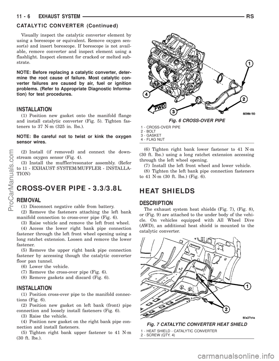
manifold connection to cross-over pipe (Fig. 6).
(3) Raise vehicle and remove the left front wheel.
(4) Access the lower right bank pipe connection
fastener through the left front wheel opening using a
long ratchet extension. Loosen and remove the lower
fastener.
(5) Remove the upper right bank pipe connection
fastener by accessing though the catalytic converter
floor pan tunnel.
(6) Lower the vehicle.
(7) Remove the cross-over pipe (Fig. 6).
(8) Remove gaskets and discard (Fig. 6).
INSTALLATION
(1) Position cross-over pipe to the manifold connec-
tions (Fig. 6).
(2) Position new gasket on left bank (front) pipe
connection and loosely install fasteners (Fig. 6).
(3) Raise the vehicle.
(4) Position new gasket on the right bank pipe con-
nection and install fasteners.
(5) Tighten right bank upper fastener to 41 N´m
(30 ft. lbs.).(6) Tighten right bank lower fastener to 41 N´m
(30 ft. lbs.) using a long ratchet extension accessing
through the left wheel opening.
(7) Install the left front wheel and lower vehicle.
(8) Tighten the left bank pipe connection fasteners
to 41 N´m (30 ft. lbs.) (Fig. 6).
HEAT SHIELDS
DESCRIPTION
The exhaust system heat shields (Fig. 7), (Fig. 8),
or (Fig. 9) are attached to the under body of the vehi-
cle. On vehicles equipped with All Wheel Dive
(AWD), an additional heat shield is mounted to the
catalytic converter.
Fig. 6 CROSS-OVER PIPE
1 - CROSS-OVER PIPE
2 - BOLT
3 - GASKET
4 - FLAG NUT
Fig. 7 CATALYTIC CONVERTER HEAT SHIELD
1 - HEAT SHIELD - CATALYTIC CONVERTER
2 - SCREW (QTY. 4)
11 - 6 EXHAUST SYSTEMRS
CATALYTIC CONVERTER (Continued)
ProCarManuals.com
Page 1362 of 2177
nect rubber fuel fill or vent hoses from tank at this
time.
(7) Place a transmission jack under center of fuel
tank. Apply a slight amount of pressure to fuel tank
with transmission jack.
(8) Remove fuel tank mounting strap nuts from
mounting strap studs.
(9)Lower the tank just enough so that the
filler tube fitting is the highest point of the fuel
tank.
(10) Remove filler tube from fuel tank. Tank will
be drained through this fitting.
WARNING: WRAP SHOP TOWELS AROUND HOSES
TO CATCH ANY GASOLINE SPILLAGE.(11) Drain fuel tank into holding tank or a prop-
erly labeledGasolinesafety container.
CAUTION: GASOLINE OR GASOLINE VAPORS ARE
HIGHLY FLAMMABLE. A FIRE COULD OCCUR IF AN
IGNITION SOURCE IS PRESENT. NEVER DRAIN OR
STORE GASOLINE OR DIESEL FUEL IN AN OPEN
CONTAINER, DUE TO THE POSSIBILITY OF FIRE
OR EXPLOSION.
(12) If fuel pump module removal is necessary,
refer to Fuel Pump Module Removal/Installation in
this section.
SPECIFICATIONS
FUEL SYSTEM PRESSURE
400 kpa 34 kpa (58 psi 5 psi)
TORQUE
DESCRIPTION N´m Ft. Lbs. In. Lbs.
Fuel Filler Neck Clamp 3.3 30
Fuel Rail 2.4L 22 200
Fuel Rail 3.3/3.8L 11.8 105
Fuel Tank Strap 54 40
Fuel Tank T Strap 28.2 250
Fuel Filter Bolt 4.5 40
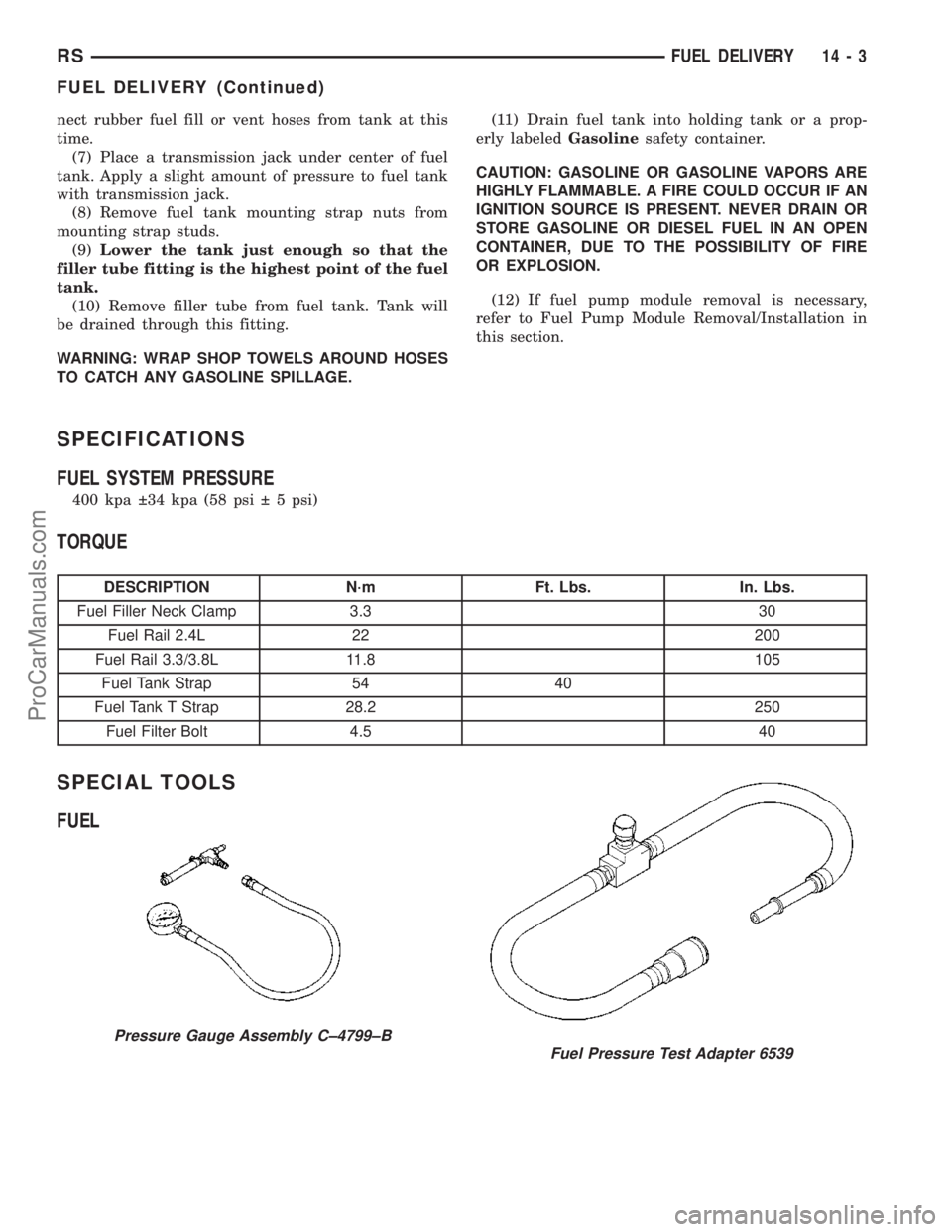
SPECIAL TOOLS
FUEL
Pressure Gauge Assembly C±4799±B
Fuel Pressure Test Adapter 6539
RSFUEL DELIVERY14-3
FUEL DELIVERY (Continued)
ProCarManuals.com
Page 1364 of 2177
OPERATION
Its resistance changes with the amount of fuel in
the tank. The float arm attached to the sensor moves
as the fuel level changes.
The fuel level input is used as an input for OBD II.
If the fuel level is below 15% or above 85% of total
tank capacity several monitors are disabled. There
are diagnostics for the level circuit open and shorted.
REMOVAL
Remove fuel pump module. Refer to Fuel Pump
Module in this section.
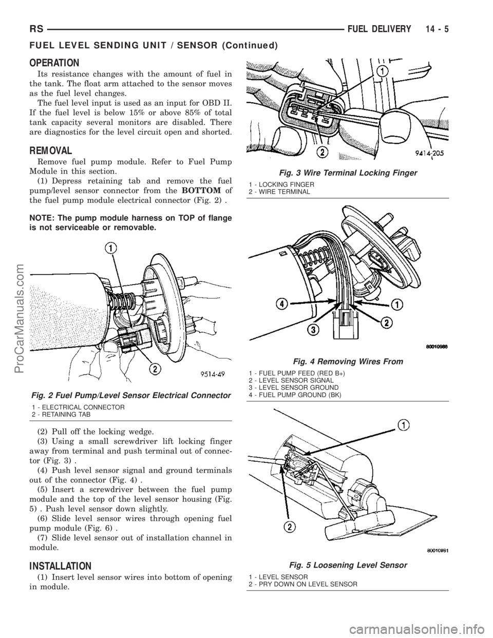
(1) Depress retaining tab and remove the fuel
pump/level sensor connector from theBOTTOMof
the fuel pump module electrical connector (Fig. 2) .
NOTE: The pump module harness on TOP of flange
is not serviceable or removable.
(2) Pull off the locking wedge.
(3) Using a small screwdriver lift locking finger
away from terminal and push terminal out of connec-
tor (Fig. 3) .
(4) Push level sensor signal and ground terminals
out of the connector (Fig. 4) .
(5) Insert a screwdriver between the fuel pump
module and the top of the level sensor housing (Fig.
5) . Push level sensor down slightly.
(6) Slide level sensor wires through opening fuel
pump module (Fig. 6) .
(7) Slide level sensor out of installation channel in
module.
INSTALLATION
(1) Insert level sensor wires into bottom of opening
in module.
Fig. 2 Fuel Pump/Level Sensor Electrical Connector
1 - ELECTRICAL CONNECTOR
2 - RETAINING TAB
Fig. 3 Wire Terminal Locking Finger
1 - LOCKING FINGER
2 - WIRE TERMINAL
Fig. 4 Removing Wires From
1 - FUEL PUMP FEED (RED B+)
2 - LEVEL SENSOR SIGNAL
3 - LEVEL SENSOR GROUND
4 - FUEL PUMP GROUND (BK)
Fig. 5 Loosening Level Sensor
1 - LEVEL SENSOR
2 - PRY DOWN ON LEVEL SENSOR
RSFUEL DELIVERY14-5
FUEL LEVEL SENDING UNIT / SENSOR (Continued)
ProCarManuals.com
Page 1366 of 2177
When installing hoses, ensure that they are routed
away from contact with other vehicle components
that could rub against them and cause failure. Avoid
contact with clamps or other components that cause
abrasions or scuffing. Ensure that rubber hoses are
properly routed and avoid heat sources.
The hose clamps have rolled edges to prevent the
clamp from cutting into the hose. Only use clamps
that are original equipment or equivalent. Other
types of clamps may cut into the hoses and cause
high pressure fuel leaks. Tighten hose clamps to 1
N´m (9 in. lbs.) torque.
Inspect all hose connections such as clamps, cou-
plings and fittings to make sure they are secure and
leaks are not present. The component should be
replaced immediately if there is any evidence of deg-
radation that could result in failure.
Never attempt to repair a plastic fuel line/tube.
Replace as necessary.
Avoid contact of any fuel tubes/hoses with other
vehicle components that could cause abrasions or
scuffing. Be sure that the plastic fuel lines/tubes are
properly routed to prevent pinching and to avoid heat
sources.
FUEL PRESSURE REGULATOR
OPERATION
The fuel system uses a nonadjustable pressure reg-
ulator that maintains fuel system pressure at
approximately 400 34 kPa (58 5 psi). The fuel
pressure regulator contains a diaphragm, calibrated
spring and a fuel return valve. The spring pushes
down on the diaphragm and closes off the fuel return
port. System fuel pressure reflects the amount of fuel
pressure required to open the return port.
The pressure regulator is a mechanical device that
is NOT controlled by the PCM or engine vacuum.
REMOVAL
The fuel pressure regulator is part of the fuel
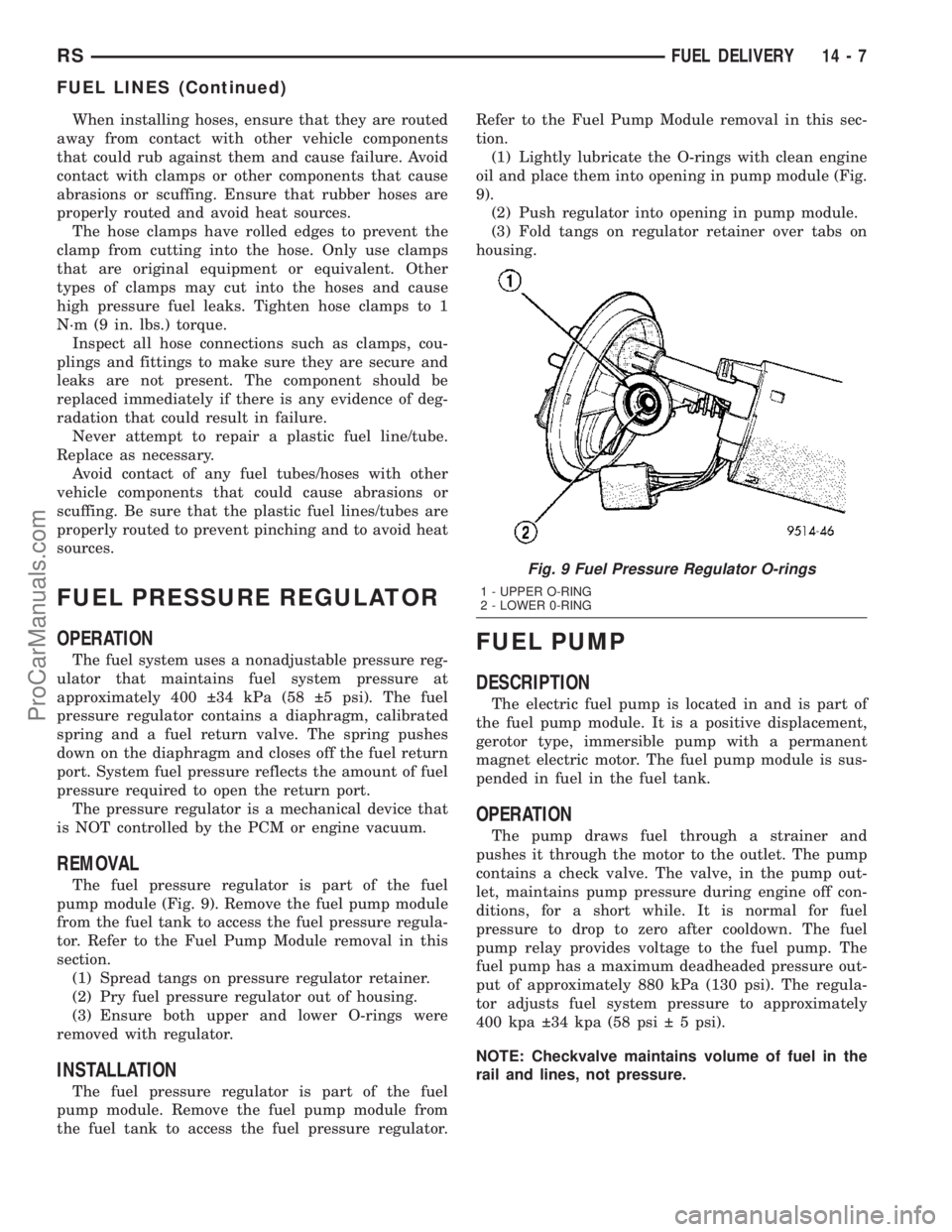
pump module (Fig. 9). Remove the fuel pump module
from the fuel tank to access the fuel pressure regula-
tor. Refer to the Fuel Pump Module removal in this
section.
(1) Spread tangs on pressure regulator retainer.
(2) Pry fuel pressure regulator out of housing.
(3) Ensure both upper and lower O-rings were
removed with regulator.
INSTALLATION
The fuel pressure regulator is part of the fuel
pump module. Remove the fuel pump module from
the fuel tank to access the fuel pressure regulator.Refer to the Fuel Pump Module removal in this sec-
tion.
(1) Lightly lubricate the O-rings with clean engine
oil and place them into opening in pump module (Fig.
9).
(2) Push regulator into opening in pump module.
(3) Fold tangs on regulator retainer over tabs on
housing.
FUEL PUMP
DESCRIPTION
The electric fuel pump is located in and is part of
the fuel pump module. It is a positive displacement,
gerotor type, immersible pump with a permanent
magnet electric motor. The fuel pump module is sus-
pended in fuel in the fuel tank.
OPERATION
The pump draws fuel through a strainer and
pushes it through the motor to the outlet. The pump
contains a check valve. The valve, in the pump out-
let, maintains pump pressure during engine off con-
ditions, for a short while. It is normal for fuel
pressure to drop to zero after cooldown. The fuel
pump relay provides voltage to the fuel pump. The
fuel pump has a maximum deadheaded pressure out-
put of approximately 880 kPa (130 psi). The regula-
tor adjusts fuel system pressure to approximately
400 kpa 34 kpa (58 psi 5 psi).
NOTE: Checkvalve maintains volume of fuel in the
rail and lines, not pressure.
Fig. 9 Fuel Pressure Regulator O-rings
1 - UPPER O-RING
2 - LOWER 0-RING
RSFUEL DELIVERY14-7
FUEL LINES (Continued)
ProCarManuals.com