2003 CHRYSLER CARAVAN seats
[x] Cancel search: seatsPage 1831 of 2177
BENCH SEATBACK PANEL
REMOVAL
(1) On third row seats remove plastic grocery bag
retainer. (Refer to 23 - BODY/SEATS/PLASTIC GRO-
CERY BAG RETAINER - REMOVAL)
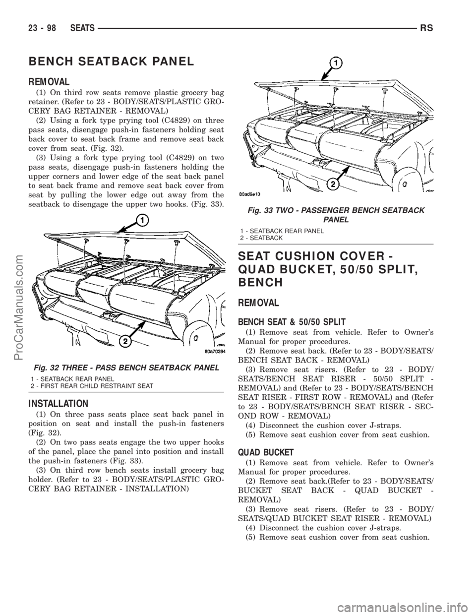
(2) Using a fork type prying tool (C4829) on three
pass seats, disengage push-in fasteners holding seat
back cover to seat back frame and remove seat back
cover from seat. (Fig. 32).
(3) Using a fork type prying tool (C4829) on two
pass seats, disengage push-in fasteners holding the
upper corners and lower edge of the seat back panel
to seat back frame and remove seat back cover from
seat by pulling the lower edge out away from the
seatback to disengage the upper two hooks. (Fig. 33).
INSTALLATION
(1) On three pass seats place seat back panel in
position on seat and install the push-in fasteners
(Fig. 32).
(2) On two pass seats engage the two upper hooks
of the panel, place the panel into position and install
the push-in fasteners (Fig. 33).
(3) On third row bench seats install grocery bag
holder. (Refer to 23 - BODY/SEATS/PLASTIC GRO-
CERY BAG RETAINER - INSTALLATION)
SEAT CUSHION COVER -
QUAD BUCKET, 50/50 SPLIT,
BENCH
REMOVAL
BENCH SEAT & 50/50 SPLIT
(1) Remove seat from vehicle. Refer to Owner's
Manual for proper procedures.
(2) Remove seat back. (Refer to 23 - BODY/SEATS/
BENCH SEAT BACK - REMOVAL)
(3) Remove seat risers. (Refer to 23 - BODY/
SEATS/BENCH SEAT RISER - 50/50 SPLIT -
REMOVAL) and (Refer to 23 - BODY/SEATS/BENCH
SEAT RISER - FIRST ROW - REMOVAL) and (Refer
to 23 - BODY/SEATS/BENCH SEAT RISER - SEC-
OND ROW - REMOVAL)
(4) Disconnect the cushion cover J-straps.
(5) Remove seat cushion cover from seat cushion.
QUAD BUCKET
(1) Remove seat from vehicle. Refer to Owner's
Manual for proper procedures.
(2) Remove seat back.(Refer to 23 - BODY/SEATS/
BUCKET SEAT BACK - QUAD BUCKET -
REMOVAL)
(3) Remove seat risers. (Refer to 23 - BODY/
SEATS/QUAD BUCKET SEAT RISER - REMOVAL)
(4) Disconnect the cushion cover J-straps.
(5) Remove seat cushion cover from seat cushion.
Fig. 32 THREE - PASS BENCH SEATBACK PANEL
1 - SEATBACK REAR PANEL
2 - FIRST REAR CHILD RESTRAINT SEAT
Fig. 33 TWO - PASSENGER BENCH SEATBACK
PANEL
1 - SEATBACK REAR PANEL
2 - SEATBACK
23 - 98 SEATSRS
ProCarManuals.com
Page 1832 of 2177
INSTALLATION
BENCH SEAT & 50/50 SPLIT
(1) Position the seat cushion cover on the cushion.
(2) Engage the J-strap retainers.
(3) Steam wrinkles from seat cushion, if necessary.
(4) Install seat risers. (Refer to 23 - BODY/SEATS/
BENCH SEAT RISER - 50/50 SPLIT - INSTALLA-
TION) and (Refer to 23 - BODY/SEATS/BENCH
SEAT RISER - SECOND ROW - INSTALLATION)
and (Refer to 23 - BODY/SEATS/BENCH SEAT
RISER - THIRD ROW - INSTALLATION)
(5) Install seat back. (Refer to 23 - BODY/SEATS/
BENCH SEAT BACK - INSTALLATION)
(6) Install seat into vehicle.
QUAD BUCKET
(1) Position the seat cushion cover on the cushion.
(2) Engage the J-strap retainers.
(3) Steam wrinkles from seat cushion, if necessary.
(4) Install seat risers. (Refer to 23 - BODY/SEATS/
QUAD BUCKET SEAT RISER - INSTALLATION)
(5) Install seat back. (Refer to 23 - BODY/SEATS/
BUCKET SEAT BACK - QUAD BUCKET - INSTAL-
LATION)
(6) Install seat into vehicle.
BENCH SEAT RISER - 50/50
SPLIT
REMOVAL
(1) Remove the seat from the vehicle. Refer to the
Owners Manual for proper procedures.
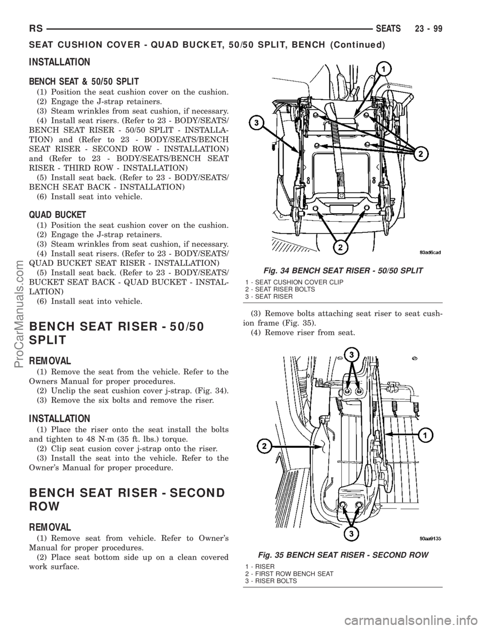
(2) Unclip the seat cushion cover j-strap. (Fig. 34).
(3) Remove the six bolts and remove the riser.
INSTALLATION
(1) Place the riser onto the seat install the bolts
and tighten to 48 N´m (35 ft. lbs.) torque.
(2) Clip seat cusion cover j-strap onto the riser.
(3) Install the seat into the vehicle. Refer to the
Owner's Manual for proper procedure.
BENCH SEAT RISER - SECOND
ROW
REMOVAL
(1) Remove seat from vehicle. Refer to Owner's
Manual for proper procedures.
(2) Place seat bottom side up on a clean covered
work surface.(3) Remove bolts attaching seat riser to seat cush-
ion frame (Fig. 35).
(4) Remove riser from seat.
Fig. 34 BENCH SEAT RISER - 50/50 SPLIT
1 - SEAT CUSHION COVER CLIP
2 - SEAT RISER BOLTS
3 - SEAT RISER
Fig. 35 BENCH SEAT RISER - SECOND ROW
1 - RISER
2 - FIRST ROW BENCH SEAT
3 - RISER BOLTS
RSSEATS23-99
SEAT CUSHION COVER - QUAD BUCKET, 50/50 SPLIT, BENCH (Continued)
ProCarManuals.com
Page 1833 of 2177
INSTALLATION
(1) Place riser in position on seat.
(2) Install bolts attaching seat riser to seat cush-
ion frame (Fig. 35). Tighten bolts to 48 N´m (35 ft.
lbs.) torque.
(3) Install seat into vehicle.
BENCH SEAT RISER - THIRD
ROW
REMOVAL
(1) Remove seat track. (Refer to 23 - BODY/
SEATS/BENCH SEAT TRACK - REMOVAL)
(2) Remove bolts attaching riser to seat cushion
frame and remove the riser. (Fig. 40).
INSTALLATION
(1) Place riser in position on seat.
(2) Install bolts attaching riser to seat cushion
frame (Fig. 40). Tighten nuts to 48 N´m (35 ft. lbs.)
torque.
(3) Install seat track. (Refer to 23 - BODY/SEATS/
BENCH SEAT TRACK - INSTALLATION)
SEAT BACK HINGE COVERS -
QUAD BUCKET, 50/50 SPLIT,
BENCH
REMOVAL
(1) Remove seat from vehicle. Refer to Owner's
Manual for proper procedures.
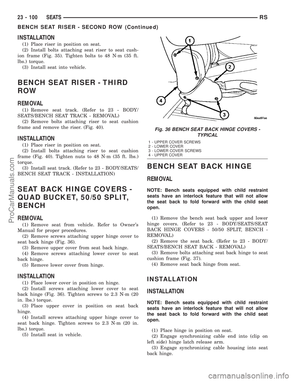
(2) Remove screws attaching upper hinge cover to
seat back hinge (Fig. 36).
(3) Remove upper cover from seat back hinge.
(4) Remove screws attaching lower cover to seat
back hinge.
(5) Remove lower cover from hinge.
INSTALLATION
(1) Place lower cover in position on hinge.
(2) Install screws attaching lower cover to seat
back hinge (Fig. 36). Tighten screws to 2.3 N´m (20
in. lbs.) torque.
(3) Place upper cover in position on seat back
hinge.
(4) Install screws attaching upper hinge cover to
seat back hinge. Tighten screws to 2.3 N´m (20 in.
lbs.) torque.
(5) Install seat in vehicle.
BENCH SEAT BACK HINGE
REMOVAL
NOTE: Bench seats equipped with child restraint
seats have an interlock feature that will not allow
the seat back to fold forward with the child seat
open.
(1) Remove the bench seat back upper and lower
hinge covers. (Refer to 23 - BODY/SEATS/SEAT
BACK HINGE COVERS - 50/50 SPLIT, BENCH -
REMOVAL)
(2) Remove the seat back. (Refer to 23 - BODY/
SEATS/BENCH SEAT BACK - REMOVAL)
(3) Remove bolts attaching seat back hinge to seat
cushion frame (Fig. 37).
(4) Remove seat back hinge from seat.
INSTALLATION
INSTALLATION
NOTE: Bench seats equipped with child restraint
seats have an interlock feature that will not allow
the seat back to fold forward with the child seat
open.
(1) Place hinge in position on seat.
(2) Engage synchronizing cable end into (clip on
left side) hinge latch release arm.
(3) Engage synchronizing cable housing into seat
back hinge.
Fig. 36 BENCH SEAT BACK HINGE COVERS -
TYPICAL
1 - UPPER COVER SCREWS
2 - LOWER COVER
3 - LOWER COVER SCREWS
4 - UPPER COVER
23 - 100 SEATSRS
BENCH SEAT RISER - SECOND ROW (Continued)
ProCarManuals.com
Page 1834 of 2177
(4) Place seat back hinge in position on seat.
(5) Install bolts attaching seat back hinge to seat
cushion frame. Tighten bolts to 48 N´m (35 ft. lbs.)
torque.
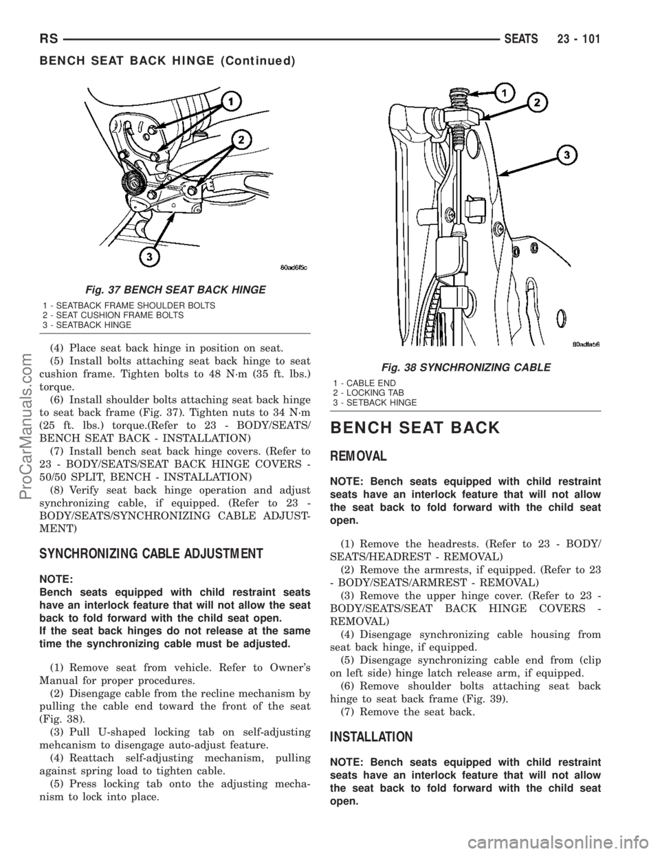
(6) Install shoulder bolts attaching seat back hinge
to seat back frame (Fig. 37). Tighten nuts to 34 N´m
(25 ft. lbs.) torque.(Refer to 23 - BODY/SEATS/
BENCH SEAT BACK - INSTALLATION)
(7) Install bench seat back hinge covers. (Refer to
23 - BODY/SEATS/SEAT BACK HINGE COVERS -
50/50 SPLIT, BENCH - INSTALLATION)
(8) Verify seat back hinge operation and adjust
synchronizing cable, if equipped. (Refer to 23 -
BODY/SEATS/SYNCHRONIZING CABLE ADJUST-
MENT)
SYNCHRONIZING CABLE ADJUSTMENT
NOTE:
Bench seats equipped with child restraint seats
have an interlock feature that will not allow the seat
back to fold forward with the child seat open.
If the seat back hinges do not release at the same
time the synchronizing cable must be adjusted.
(1) Remove seat from vehicle. Refer to Owner's
Manual for proper procedures.
(2) Disengage cable from the recline mechanism by
pulling the cable end toward the front of the seat
(Fig. 38).
(3) Pull U-shaped locking tab on self-adjusting
mehcanism to disengage auto-adjust feature.
(4) Reattach self-adjusting mechanism, pulling
against spring load to tighten cable.
(5) Press locking tab onto the adjusting mecha-
nism to lock into place.
BENCH SEAT BACK
REMOVAL
NOTE: Bench seats equipped with child restraint
seats have an interlock feature that will not allow
the seat back to fold forward with the child seat
open.
(1) Remove the headrests. (Refer to 23 - BODY/
SEATS/HEADREST - REMOVAL)
(2) Remove the armrests, if equipped. (Refer to 23
- BODY/SEATS/ARMREST - REMOVAL)
(3) Remove the upper hinge cover. (Refer to 23 -
BODY/SEATS/SEAT BACK HINGE COVERS -
REMOVAL)
(4) Disengage synchronizing cable housing from
seat back hinge, if equipped.
(5) Disengage synchronizing cable end from (clip
on left side) hinge latch release arm, if equipped.
(6) Remove shoulder bolts attaching seat back
hinge to seat back frame (Fig. 39).
(7) Remove the seat back.
INSTALLATION
NOTE: Bench seats equipped with child restraint
seats have an interlock feature that will not allow
the seat back to fold forward with the child seat
open.
Fig. 37 BENCH SEAT BACK HINGE
1 - SEATBACK FRAME SHOULDER BOLTS
2 - SEAT CUSHION FRAME BOLTS
3 - SEATBACK HINGE
Fig. 38 SYNCHRONIZING CABLE
1 - CABLE END
2 - LOCKING TAB
3 - SETBACK HINGE
RSSEATS23 - 101
BENCH SEAT BACK HINGE (Continued)
ProCarManuals.com
Page 1835 of 2177

(1) Install the seat back.
(2) Install the shoulder bolts attaching the seat
back hinge to the seat back frame and tighten to 34
N´m (25 ft. lbs.) torque.
(3) Connect the synchronizing cable end from (clip
on left side) hinge latch release arm, if equipped.
(4) Connect the synchronizing cable housing to the
seat back hinge, if equipped.
(5) Install the upper hinge cover. (Refer to 23 -
BODY/SEATS/SEAT BACK HINGE - INSTALLA-
TION)
(6) Install the armrests, if equipped. (Refer to 23 -
BODY/SEATS/ARMREST - INSTALLATION)
(7) Install the headrest sleeves. (Refer to 23 -
BODY/SEATS/HEADREST SLEEVE - INSTALLA-
TION)
(8) Adjust synchronizing cable, if equipped. (Refer
to 23 - BODY/SEATS/SYNCHRONIZING CABLE
ADJUSTMENT)
BENCH SEAT BACK COVER
REMOVAL
(1) Remove the bench seat back. (Refer to 23 -
BODY/SEATS/BENCH SEAT BACK - REMOVAL)
(2) Remove the bench seatback panel. (Refer to 23
- BODY/SEATS/BENCH SEATBACK PANEL -
REMOVAL)
(3) Disconnect the cover J-straps.
(4) Remove the seat back cover from the seat back
assembly.
INSTALLATION
(1) Install seat back cover onto the seat back
frame and cushion assembly.(2) Connect the J-straps.
(3) Install the bench seatback panel. (Refer to 23 -
BODY/SEATS/BENCH SEATBACK PANEL -
INSTALLATION)
(4) Install the seat back. (Refer to 23 - BODY/
SEATS/BENCH SEAT BACK - INSTALLATION)
BENCH SEAT TRACK
REMOVAL
(1) Remove second row seat from vehicle. Refer to
Owner's Manual for proper procedure.
(2) Place seat on clean covered work surface.
(3) Disengage seat track adjuster link wire from
track being removed.
(4) Remove nuts attaching track to seat riser (Fig.
40).
(5) Remove track from seat riser.
INSTALLATION
(1) Place track in position on seat riser.
(2) Install nuts attaching track to seat riser. (Fig.
40). Tighten nuts to 48 N´m (35 ft. lbs.) torque.
(3) Engage seat track adjuster link wire onto track
being installed.
(4) Install second row seat into vehicle.
Fig. 39 SEAT BACK HINGE - TYPICAL
1 - SEATBACK FRAME SHOULDER BOLTS
2 - SEAT CUSHION FRAME BOLTS
3 - SEATBACK HINGE
Fig. 40 BENCH SEAT TRACK
1 - SEAT TRACK ADJUSTER LINK
2 - RISER
3 - SEAT TRACK NUTS
4 - SEAT TRACK
5 - RISER BOLTS
23 - 102 SEATSRS
BENCH SEAT BACK (Continued)
ProCarManuals.com
Page 1836 of 2177
PLASTIC GROCERY BAG
RETAINER
REMOVAL
3-PASS BENCH SEAT
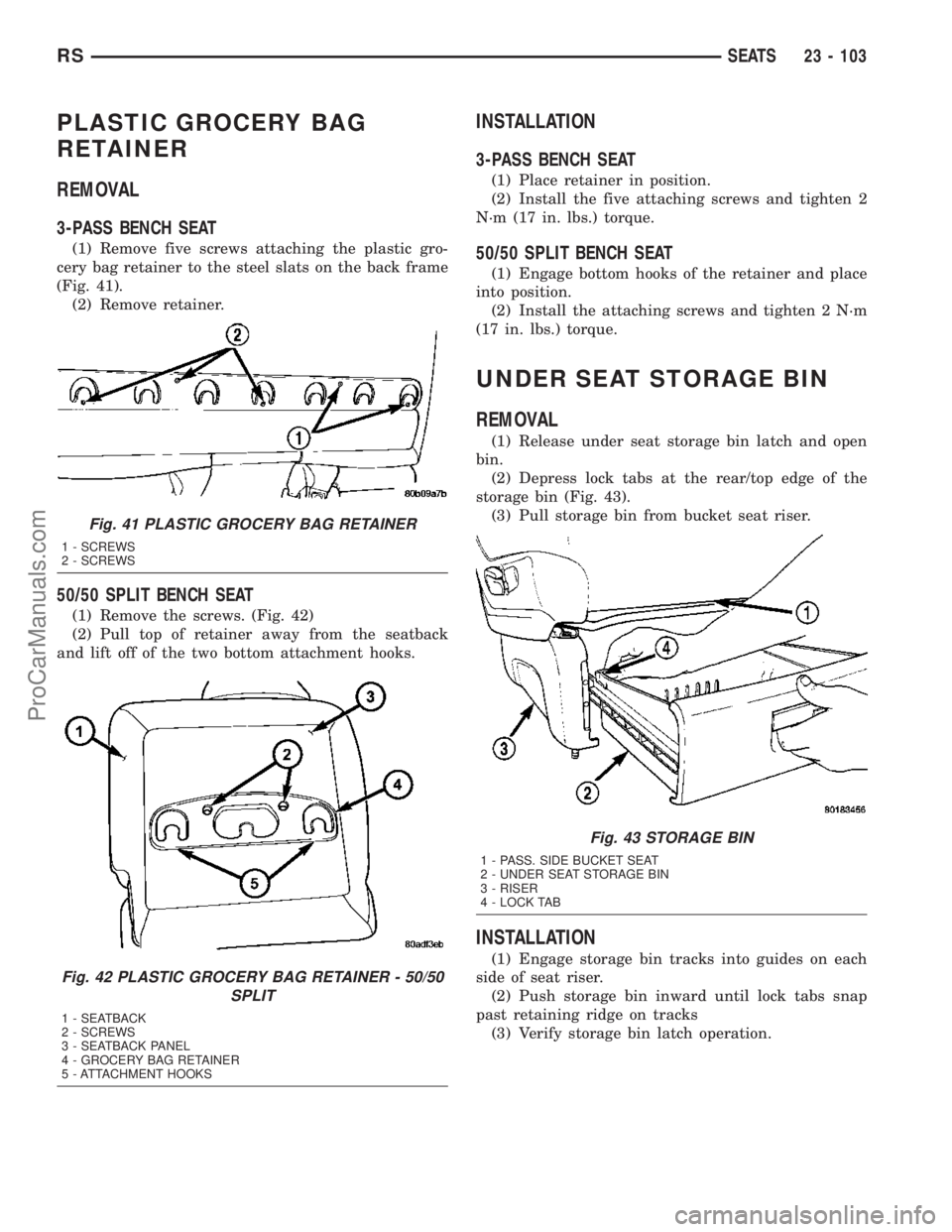
(1) Remove five screws attaching the plastic gro-
cery bag retainer to the steel slats on the back frame
(Fig. 41).
(2) Remove retainer.
50/50 SPLIT BENCH SEAT
(1) Remove the screws. (Fig. 42)
(2) Pull top of retainer away from the seatback
and lift off of the two bottom attachment hooks.
INSTALLATION
3-PASS BENCH SEAT
(1) Place retainer in position.
(2) Install the five attaching screws and tighten 2
N´m (17 in. lbs.) torque.
50/50 SPLIT BENCH SEAT
(1) Engage bottom hooks of the retainer and place
into position.
(2) Install the attaching screws and tighten 2 N´m
(17 in. lbs.) torque.
UNDER SEAT STORAGE BIN
REMOVAL
(1) Release under seat storage bin latch and open
bin.
(2) Depress lock tabs at the rear/top edge of the
storage bin (Fig. 43).
(3) Pull storage bin from bucket seat riser.
INSTALLATION
(1) Engage storage bin tracks into guides on each
side of seat riser.
(2) Push storage bin inward until lock tabs snap
past retaining ridge on tracks
(3) Verify storage bin latch operation.
Fig. 41 PLASTIC GROCERY BAG RETAINER
1 - SCREWS
2 - SCREWS
Fig. 42 PLASTIC GROCERY BAG RETAINER - 50/50
SPLIT
1 - SEATBACK
2 - SCREWS
3 - SEATBACK PANEL
4 - GROCERY BAG RETAINER
5 - ATTACHMENT HOOKS
Fig. 43 STORAGE BIN
1 - PASS. SIDE BUCKET SEAT
2 - UNDER SEAT STORAGE BIN
3 - RISER
4 - LOCK TAB
RSSEATS23 - 103
ProCarManuals.com
Page 1837 of 2177
UNDER SEAT STORAGE BIN
GUIDE
REMOVAL
(1) Remove under seat storage bin. (Refer to 23 -
BODY/SEATS/UNDER SEAT STORAGE BIN -
REMOVAL)
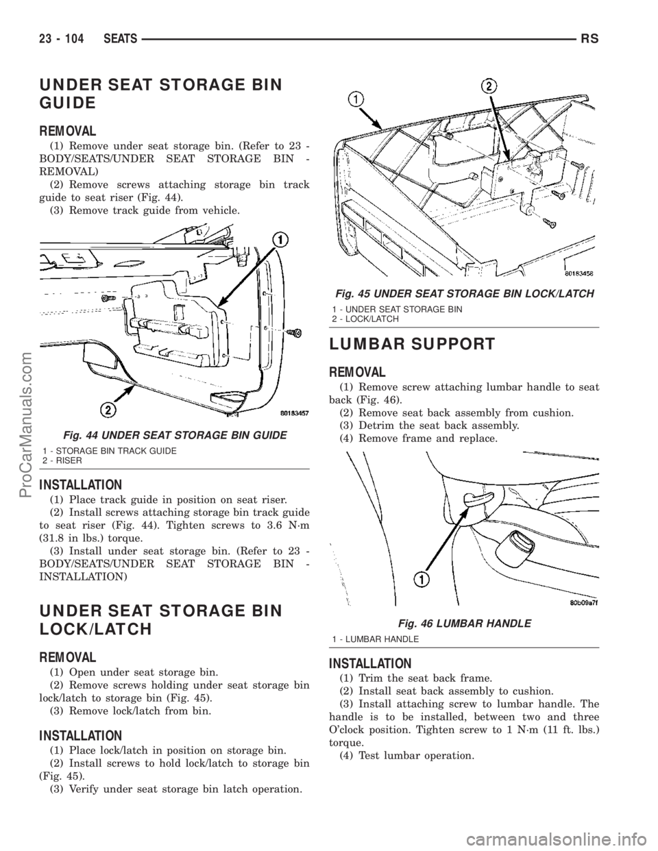
(2) Remove screws attaching storage bin track
guide to seat riser (Fig. 44).
(3) Remove track guide from vehicle.
INSTALLATION
(1) Place track guide in position on seat riser.
(2) Install screws attaching storage bin track guide
to seat riser (Fig. 44). Tighten screws to 3.6 N´m
(31.8 in lbs.) torque.
(3) Install under seat storage bin. (Refer to 23 -
BODY/SEATS/UNDER SEAT STORAGE BIN -
INSTALLATION)
UNDER SEAT STORAGE BIN
LOCK/LATCH
REMOVAL
(1) Open under seat storage bin.
(2) Remove screws holding under seat storage bin
lock/latch to storage bin (Fig. 45).
(3) Remove lock/latch from bin.
INSTALLATION
(1) Place lock/latch in position on storage bin.
(2) Install screws to hold lock/latch to storage bin
(Fig. 45).
(3) Verify under seat storage bin latch operation.
LUMBAR SUPPORT
REMOVAL
(1) Remove screw attaching lumbar handle to seat
back (Fig. 46).
(2) Remove seat back assembly from cushion.
(3) Detrim the seat back assembly.
(4) Remove frame and replace.
INSTALLATION
(1) Trim the seat back frame.
(2) Install seat back assembly to cushion.
(3) Install attaching screw to lumbar handle. The
handle is to be installed, between two and three
O'clock position. Tighten screw to 1 N´m (11 ft. lbs.)
torque.
(4) Test lumbar operation.
Fig. 44 UNDER SEAT STORAGE BIN GUIDE
1 - STORAGE BIN TRACK GUIDE
2 - RISER
Fig. 45 UNDER SEAT STORAGE BIN LOCK/LATCH
1 - UNDER SEAT STORAGE BIN
2 - LOCK/LATCH
Fig. 46 LUMBAR HANDLE
1 - LUMBAR HANDLE
23 - 104 SEATSRS
ProCarManuals.com
Page 1849 of 2177
SYMPTOM POSSIBLE CAUSE
Buzz, Squeak,Rattles from sunroof Loose or broken attaching hardware.
No lubracation in track.
Worn or broken mechanism.
Cables bunched or kinked
Sunshade will not function or does not
operate smoothlySunshade feet are missing, broken or loose.
No lubracation in track.
Track obstructions or interference.
Glass movement not consistant or glass does
not operate smoothlyGlass and Track timing.
Glass and Track alignment
Cables and Guide alignment
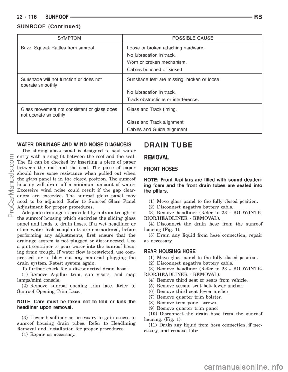
WATER DRAINAGE AND WIND NOISE DIAGNOSIS
The sliding glass panel is designed to seal water
entry with a snug fit between the roof and the seal.
The fit can be checked by inserting a piece of paper
between the roof and the seal. The piece of paper
should have some resistance when pulled out when
the glass panel is in the closed position. The sunroof
housing will drain off a minimum amount of water.
Excessive wind noise could result if the gap clear-
ances are exceeded. The sunroof glass panel may
need to be adjusted. Refer to Sunroof Glass Panel
Adjustment for proper procedures.
Adequate drainage is provided by a drain trough in
the sunroof housing which encircles the sliding glass
panel and leads to drain hoses. If a wet headliner or
other water leak complaints are encountered, before
performing any adjustments, first ensure that the
drainage system is not plugged or disconnected. Use
a pint container to pour water into the sunroof hous-
ing drain trough. If water flow is restricted, use com-
pressed air to blow out any material plugging the
drain system. Retest system again.
To further check for a disconnected drain hose:
(1) Remove A-pillar trim, sun visors, and map
lamps/mini console.
(2) Remove sunroof opening trim lace. Refer to
Sunroof Opening Trim Lace.
NOTE: Care must be taken not to fold or kink the
headliner upon removal.
(3) Lower headliner as necessary to gain access to
sunroof housing drain tubes. Refer to Headlining
Removal and Installation for proper procedures.
(4) Repair as necessary.
DRAIN TUBE
REMOVAL
FRONT HOSES
NOTE: Front A-pillars are filled with sound deaden-
ing foam and the front drain tubes are sealed into
the pillars.
(1) Move glass panel to the fully closed position.
(2) Disconnect negative battery cable.
(3) Remove headliner (Refer to 23 - BODY/INTE-
RIOR/HEADLINER - REMOVAL).
(4) Disconnect the drain hose from the sunroof
housing (Fig. 1).
(5) Drain any liquid from hose connection, repair
as necessary.
REAR HOUSING HOSE
(1) Move glass panel to the fully closed position.
(2) Disconnect negative battery cable.
(3) Remove headliner (Refer to 23 - BODY/INTE-
RIOR/HEADLINER - REMOVAL).
(4) Remove third seat or seats from vehicle.
(5) Remove second seat belt lower anchor.
(6) Remove third seat lower anchor.
(7) Remove quarter trim bolster.
(8) Remove trim panel screws.
(9) Remove quarter trim panel
(10) Disconnect the drain hose from the sunroof
housing. (Fig. 1).
(11) Drain any liquid from hose connection, if nec-
essary, and remove tube.
23 - 116 SUNROOFRS
SUNROOF (Continued)
ProCarManuals.com