2003 CHRYSLER CARAVAN ignition
[x] Cancel search: ignitionPage 2000 of 2177
²Air recirculation button. A Recirculation symbol
appears in the display when the button is pressed, or
when the system exceeds 80 percent circulated air
under automatic control due to high air conditioning
demand.
²Rear window defogger on/off switch. A graphic
symbol shows when the defroster is on.
²An air conditioning button that allows the com-
pressor to be turned off. A Snowflake symbol is illu-
minated when air conditioning is on, whether under
manual or automatic control.
²Rotary knob for front fan speed selection can
override the automatic controls. LEDs surrounding
the knob show the current setting.
²Rotary knob for control of the Rear system.
²A rotary knob for mode control can override the
automatic controls. LEDs surrounding the knob show
the current setting.
²Computer logic remembers the settings of the
controls when the ignition is turned off and retains
those settings after a restart. If the system is off
when the ignition is turned off it will be off when the
engine is restarted, etc.
²Computer logic provides variable air recircula-
tion under high temperature and humidity condi-
tions. Because recirculation is generally accompanied
by increased fan noise, the proportion of recirculated
to outside air gradually approaches full recirculation
over a broad temperature range.
²Computer logic enables additional heat for diesel
equipped vehicles via a supplemental diesel heater.
REAR CONTROL PANEL
A rear control panel centrally mounted on the
headliner includes a vacuum-flourescent digital dis-
play, a rocker control for temperature and rotary con-
trols for adjustment of mode and fan speed control of
the rear unit by intermediate seat passengers.
OPERATION
OPERATION - DUAL ZONE
²The mode control knob enables continously vari-
able proportioning of air flow between modes but has
detents adjacent to each icon.
²The blower control provides five separate speeds.
²When the fan is off, the HVAC computer closes
the recirculation door to prevent outside air from
entering the passenger compartment.
²Interior air may be recirculated to speed up
heating or cooling in all modes except defrost and
mix by pressing the Recirculate button on the control
panel.
²To reduce humidity for rapid defogging the A/C
compressor runs automatically in modes from ªmix'to full defrost when outside temperatures are above
freezing.
²Air conditioning is available in any mode by
pressing the snowflake, A/C on/off, button.
OPERATION - MANUAL THREE ZONE
FRONT CONTROL PANEL
²Primary control of the rear compartment unit is
on the instrument panel. This control allows the
driver to set the rear compartment fan speed, to turn
the rear unit off, or to give control to the intermedi-
ate seat occupants by switching to the REAR posi-
tion. When the rear unit is controlled from the
instrument panel, rear air temperature is based on
the driver-side temperature control position, and the
mode (floor or overhead air) is based on the front
control's mode position.
²The mode control knob enables continously vari-
able proportioning of air flow between modes but has
detents adjacent to each icon.
²The blower control provides five separate speeds
and Off. When the fan is off, the HVAC computer
closes the recirculation door to prevent outside air
from entering the passenger compartment.
²Interior air may be recirculated to speed up
heating or cooling in all modes exccept defrost and
mix by pressing the Recirculate button on the control
panel.
²To reduce humidity for rapid defogging the A/C
compressor runs automatically in modes from ªmix'
to full defrost when outside temperatures are above
freezing.
²Air conditioning is available in any mode by
pressing the snowflake, A/C on/off, button.
REAR CONTROL PANEL
With the rear control active, temperature selection
dictates indirectly the mode (floor or overhead air) of
the rear unit: a low temperature setting directs flow
to the overhead outlets and a high temperature set-
ting to the floor.
OPERATION - THREE ZONE ATC
Comfort temperature or perceived temperature is
affected by air flow, sun impinging on exposed skin,
etc. The air temperature may be higher or lower than
the comfort temperature. Two infrared sensors, in the
instrument panel center stack i measure the temper-
ature of the occupants to determine their comfort
level relative to the selected comfort temperature.
The HVAC computer in the control module adjusts
the air flow rate and temperature to maintain the
customer-perceived comfort temperature. The air
temperature in the passenger compartment at any
time may be slightly higher or lower than the com-
RSHEATING & AIR CONDITIONING24-3
HEATING & AIR CONDITIONING (Continued)
ProCarManuals.com
Page 2001 of 2177
fort temperature. For instance, on sunny summer
days the air flow will probably be cooler than the
comfort temperature; on cold or cloudy days and at
night it will probably be slightly warmer. Infrared
Three-Zone Temperature Control provides side-to-
side and front-to-rear variation in comfort tempera-
ture settings. The Infrared Three-Zone Automatic
Temperature Control fan provides a continuously
variable air flow rate to meet occupant comfort
requirements.
FRONT CONTROL PANEL
²AUTO HI/LO± This system features two sets of
automatic control logic that allow either a rapid cool-
down rate or a somewhat slower cool-down rate with
less fan noise. HI-AUTO controls the system to reach
its assigned temperature quickly with a higher fan
speed. LO-AUTO controls the system to reach its
assigned temperature somewhat slower with less fan
noise. Both modes will automatically engage auto
recirculation.
²DE-FROST± The de-frost function is active
when the rear window defogger function is active or
when the defog/defrost mode is selected.
²RECIRC± The RECIRC button will close the
air inlet door. If the system is in auto recirc (indica-
tor being displayed automatically), pressing the man-
ual recirc button will disable the auto recirc function
until one of the auto keys are pressed or the ignition
is cycled. If Auto HI/LO is pressed while manual
recirc is active, manual recirc will be deactivated.
²REAR WINDOW DEFOGGER± Pushing the
button sends a PCI bus message to the Intelligent
Power Module which controls the Rear Window
Defogger and side view mirror (if equipped) circuitry.
The defogger function will be active for 10 minutes
and can be turned off by a switch press. The defogger
will function while the control is in the ON mode.
²FAN/MODE± The Fan and Mode knobs have
17 manual selectable positions. Manually changing
either of the rotary knobs for mode or fan speed set-
tings makes control of that function alone manual for
as long as the ignition is on. If only one is changed
manually, the other remains under automatic control.
Pressing the HI-AUTO/LO-AUTO rocker switch
restores full automatic control.
²REAR CONTROL± When the Rear System
control knob is moved to the OFF position, there will
be a delay of approximately 1 second before the sys-
tem actually turns off. This delay is to prevent an
undesired blower dropout if the knob is moved
through OFF to the other selections.
²BLOWER DELAY TIMER± The word DELAY
is displayed at start-up to signify that the system is
waiting so that cold air will not be blowing. This tells
the operator that it is unnecessary to turn the sys-tem off, raise the temperature setting or turn the fan
speed setting down to prevent cold air from blowing.
A countdown in minutes and seconds until the engine
is warm enough to begin delivering heat to the pas-
sengers alternates with the DELAY message at 25
second intervals. This countdown is based on actual
measurement of the rate of engine coolant tempera-
ture change. During the delay time, Defrost mode is
selected and the fan operates at a low speed to keep
the windshield fog free.
REAR CONTROL PANEL
Primary control of the rear compartment unit is in
the instrument panel center stack. The rear unit con-
trol knob there allows the driver to turn the rear
unit off, allow control by the intermediate seat occu-
pants by switching to the REAR position, or provide
fully automatic control based on the temperature set-
ting shown on the front control display.
²REAR CONTROL± Selecting automatic control
of the rear unit at the instrument panel, illuminates
a Locked Padlock in the rear control panel display.
Selecting REAR activates the rear control panel and
the Padlock then appears unlocked.
²FAN KNOB± The rear fan control has Off and
AUTO positions and a range of manual speed set-
tings that override the AUTO setting.
²MODE KNOB± The mode control allows inter-
mediate seat occupants to manually override the
automatic mode and select any balance of air flow
between overhead and floor outlets from full over-
head to full floor.
²SET TEMP± The rear set temp control will
operate identical to the front controls. If the front
control rear set temp button is pressed simulta-
neously with the rear control head, then the front
control head press events shall have priority, i.e. if
the front user presses Rear Set Temp down and the
rear user presses Set Temp up, then the rear set
temp will decrease.
DIAGNOSIS AND TESTING
DIAGNOSIS AND TESTING - A/C COOL DOWN
TEST
The heater-A/C control module can perform an A/C
cool down test, which is a test performed during the
manufacturing process to confirm that the air condi-
tioning system is performing satisfactorily. This test
can also provide a quick confirmation of air condi-
tioning system performance to the service technician.
If the test is completed satisfactorily, no further ser-
vice is required. If the test is failed, proceed to the
A/C Performance Test to confirm the a/c system is
operating properly, or use a DRBIIItscan tool to
24 - 4 HEATING & AIR CONDITIONINGRS
HEATING & AIR CONDITIONING (Continued)
ProCarManuals.com
Page 2002 of 2177
diagnose the A/C system control and distribution sys-
tems. Refer to the appropriate diagnostic informa-
tion.
MANUAL TEMPERATURE CONTROL
The front blower speed and rear blower speed (if
equipped with rear HVAC) must be set to High and
the evaporator temperature sensor must be greater
than 55É F or the test will fail immediately. The test
is activated by depressing the A/C and PWR buttons
simultaneously and holding them depressed for no
less than five seconds. The PWR and A/C LEDs will
blink on and off until the test is complete. If the
LEDs stop blinking before two minutes, then the cool
down test has been completed successfully. If the two
minutes expire without the expansion valve temper-
ature reaching 20É F less than the outside air tem-
perature, then the cool down test has been failed and
further A/C system diagnosis is required. If the test
is failed, the LEDs will continue to blink until the
vehicle has been driven for greater than (8 miles).
AUTOMATIC TEMPERATURE CONTROL
The ambient air temperature in the room where
the vehicle will be tested must be a minimum of 21É
C (70ÉF) for this test. The test is activated by
depressing the A/C and PWR buttons simultaneously
and holding them depressed for no less than four sec-
onds. The snowflake icon and the DELAY text in the
ATC display will blink on and off alternately until
the test is complete. If the snowflake icon and the
DELAY text stop blinking before two minutes, then
the cool down test has been completed successfully. If
the two minutes expire without the evaporator tem-
perature reaching 20É F less than the evaporator ini-
tial temperature, then the cool down test has been
failed and further A/C system diagnosis is required.
If the test is failed, the snowflake icon and the
DELAY text will continue to blink across ignition
cycles until the vehicle has been driven for greater
than (8 miles).
DIAGNOSIS AND TESTING - A/C
PERFORMANCE TEST
An air conditioning performance test is the best
way to determine whether the system is performing
up to standard. This test also provides valuable clues
as to the possible cause of trouble with the air con-
ditioning system. The ambient air temperature in the
location where the vehicle will be tested must be a
minimum of 21É C (70ÉF) for this test.
WARNING: REFER TO THE APPLICABLE WARN-
INGS AND CAUTIONS FOR THIS SYSTEM BEFOREPERFORMING THE FOLLOWING OPERATION.
(Refer to 24 - HEATING & AIR CONDITIONING/
PLUMBING - FRONT - WARNING - A/C PLUMBING)
and (Refer to 24 - HEATING & AIR CONDITIONING/
PLUMBING - FRONT - CAUTION - A/C PLUMBING).
NOTE: When connecting the service equipment
coupling to the line fitting, verify that the valve of
the coupling is fully closed. This will reduce the
amount of effort required to make the connection.
(1) Connect a tachometer to monitor the engine
speed.
(2) Remove the caps from the refrigerant system
service ports and attach a manifold gauge set to
monitor the refrigerant system pressures.
(3) Set the heater-air conditioner controls so that
the compressor is engaged, the air within the vehicle
is being recirculated, the output air is directed
through the panel outlets, the temperature control is
in the full cool position, and the blower motor is oper-
ating at its highest speed.
(4) Start the engine and allow the engine to oper-
ate for about five minutes or until it reaches normal
operating temperature. Then hold the engine speed
at 1000 rpm with the compressor clutch engaged. If
the compressor clutch does not engage, proceed with
diagnosis of the compressor clutch coil. (Refer to 24 -
HEATING & AIR CONDITIONING/CONTROLS -
FRONT/COMPRESSOR CLUTCH COIL - DIAGNO-
SIS AND TESTING).
(5) Close all the vehicle windows and doors.
(6) Insert a thermometer in the left center panel
outlet and operate the engine for five minutes.
(7) With the compressor clutch engaged, record the
left center panel outlet discharge air temperature,
the discharge pressure (high side service port), and
the suction pressure (low side service port). The com-
pressor clutch may cycle, depending upon the ambi-
ent temperature and humidity. If the clutch cycles,
use the readings obtained before the clutch disen-
gaged.
(8) Compare the discharge air temperature read-
ing to the Performance Temperature and Pressure
chart. If the temperature reading is high, check the
refrigerant system for leaks and proper refrigerant
charge level. (Refer to 24 - HEATING & AIR CONDI-
TIONING/PLUMBING - FRONT/REFRIGERANT -
DIAGNOSIS AND TESTING - REFRIGERANT SYS-
TEM LEAKS) and (Refer to 24 - HEATING & AIR
CONDITIONING/PLUMBING - FRONT/REFRIGER-
ANT - DIAGNOSIS AND TESTING - REFRIGER-
ANT SYSTEM CHARGE LEVEL).
RSHEATING & AIR CONDITIONING24-5
HEATING & AIR CONDITIONING (Continued)
ProCarManuals.com
Page 2005 of 2177
CONTROLS - FRONT
TABLE OF CONTENTS
page page
A/C HEATER CONTROL
STANDARD PROCEDURE - HEATER-A/C
CONTROL CALIBRATION................8
REMOVAL.............................9
INSTALLATION..........................9
A/C PRESSURE TRANSDUCER
DESCRIPTION - A/C PRESSURE
TRANSDUCER.......................10
OPERATION...........................10
DIAGNOSIS AND TESTING - A/C PRESSURE
TRANSDUCER.......................10
REMOVAL.............................10
INSTALLATION.........................11
BLEND DOOR ACTUATOR
DESCRIPTION.........................11
OPERATION...........................11
REMOVAL.............................12
INSTALLATION.........................12
BLOWER MOTOR RELAY
DESCRIPTION.........................13
OPERATION...........................13
DIAGNOSIS AND TESTING - BLOWER
MOTOR RELAY.......................14
REMOVAL.............................14
INSTALLATION.........................14
BLOWER MOTOR RESISTOR
DESCRIPTION.........................14
OPERATION...........................15
DIAGNOSIS AND TESTING - BLOWER
MOTOR RESISTOR....................15
REMOVAL.............................16
INSTALLATION.........................16
COMPRESSOR CLUTCH
DESCRIPTION.........................16
OPERATION...........................17
STANDARD PROCEDURE
STANDARD PROCEDURE - COMPRESSOR
CLUTCH AIR GAP.....................17STANDARD PROCEDURE - COMPRESSOR
CLUTCH BREAK-IN....................17
REMOVAL.............................17
INSPECTION - COMPRESSOR CLUTCH/COIL . 18
INSTALLATION.........................19
COMPRESSOR CLUTCH COIL
DIAGNOSIS AND TESTING - COMPRESSOR
CLUTCH COIL........................20
COMPRESSOR CLUTCH RELAY
DESCRIPTION.........................21
OPERATION...........................21
DIAGNOSIS AND TESTING - COMPRESSOR
CLUTCH RELAY......................22
REMOVAL.............................22
INSTALLATION.........................22
EVAPORATOR TEMPERATURE SENSOR
DESCRIPTION.........................22
OPERATION...........................23
REMOVAL.............................23
INSTALLATION.........................23
INFRARED TEMPERATURE SENSOR
DESCRIPTION.........................23
OPERATION...........................24
MODE DOOR ACTUATOR
DESCRIPTION.........................24
OPERATION...........................24
REMOVAL.............................25
INSTALLATION.........................25
POWER MODULE
DESCRIPTION.........................25
OPERATION...........................26
REMOVAL.............................26
INSTALLATION.........................26
RECIRCULATION DOOR ACTUATOR
DESCRIPTION.........................27
OPERATION...........................27
REMOVAL.............................27
INSTALLATION.........................28
A/C HEATER CONTROL
STANDARD PROCEDURE - HEATER-A/C
CONTROL CALIBRATION
The heater-A/C control module must be recali-
brated each time an actuator motor or the control
module is replaced. If the vehicle is so equipped, the
calibration procedure also includes rear HVAC posi-
tions for each actuator motor.(1) Turn the ignition switch to the On position.
(2) Simultaneously depress and hold the Power
and Recirculation buttons on the heater-A/C control
for at least five seconds. The manual heater-A/C con-
trol power Light Emitting Diode (LED) and Recircu-
lation LED, or the Automatic Temperature Control
24 - 8 CONTROLS - FRONTRS
ProCarManuals.com
Page 2018 of 2177
DRBIIItscan tool to perform further diagnosis. Refer
to the appropriate diagnostic information.
TESTS
(1) Verify the battery state of charge. (Refer to 8 -
ELECTRICAL/BATTERY SYSTEM/BATTERY -
DIAGNOSIS AND TESTING).
(2) Connect an ammeter (0 to 10 ampere scale
selected) in series with the clutch coil feed terminal.
Connect a voltmeter (0 to 20 volt scale selected) to
measure voltage across the battery and the clutch
coil.
(3) With the heater-A/C control in the A/C mode
and the blower at low speed, start the engine and
allow it to run at a normal idle speed.
(4) The compressor clutch should engage immedi-
ately, and the clutch coil voltage should be within
two volts of the battery voltage. If the coil voltage is
not within two volts of battery voltage, test the
clutch coil feed circuit for excessive voltage drop. If
the compressor clutch does not engage, use a
DRBIIItscan tool to perform further diagnosis. Refer
to the appropriate diagnostic information.
(5) With the ambient temperature at 21É C (70É F),
the compressor clutch coil is acceptable if the current
draw is 2.0 to 3.7 amperes at 11.5 to 12.5 volts at the
clutch coil. If the voltage is more than 12.5 volts, add
electrical loads by turning on electrical accessories
until the voltage reads below 12.5 volts.
(a) If the compressor clutch coil current reading
is zero, the coil is open and must be replaced.
(b) If the compressor clutch coil current reading
is four amperes or more, the coil is shorted and
must be replaced.
COMPRESSOR CLUTCH RELAY
DESCRIPTION
The compressor clutch relay (Fig. 17) is a Interna-
tional Standards Organization (ISO) micro-relay.
Relays conforming to the ISO specifications have
common physical dimensions, current capacities, ter-
minal patterns, and terminal functions. The ISO
micro-relay terminal functions are the same as a con-
ventional ISO relay. However, the ISO micro-relay
terminal pattern (or footprint) is different, the cur-
rent capacity is lower, and the physical dimensions
are smaller than those of the conventional ISO relay.
The compressor clutch relay is located in the Intelli-
gent Power Module (IPM), which is in the engine
compartment near the battery. See the fuse and relay
layout map molded into the inner surface of the IPM
cover for compressor clutch relay identification and
location.The black, molded plastic case is the most visible
component of the compressor clutch relay. Five male
spade-type terminals extend from the bottom of the
base to connect the relay to the vehicle electrical sys-
tem, and the ISO designation for each terminal is
molded into the base adjacent to each terminal.
OPERATION
The compressor clutch relay is an electromechani-
cal switch that uses a low current input from the
Powertrain Control Module (PCM) to control the high
current output to the compressor clutch electromag-
netic coil. The movable common feed contact point is
held against the fixed normally closed contact point
by spring pressure. When the relay coil is energized,
an electromagnetic field is produced by the coil wind-
ings. This electromagnetic field draws the movable
relay contact point away from the fixed normally
closed contact point, and holds it against the fixed
normally open contact point. When the relay coil is
de-energized, spring pressure returns the movable
contact point back against the fixed normally closed
contact point. The resistor or diode is connected in
parallel with the relay coil in the relay, and helps to
dissipate voltage spikes and electromagnetic interfer-
ence that can be generated as the electromagnetic
field of the relay coil collapses.
The compressor clutch relay terminals are con-
nected to the vehicle electrical system through a
receptacle in the Intelligent Power Module (IPM).
The inputs and outputs of the compressor clutch
relay include:
²The common feed terminal (30) receives a bat-
tery current input from a fuse in the IPM through a
fused B(+) circuit at all times.
²The coil ground terminal (85) receives a ground
input from the PCM through the compressor clutch
relay control circuit only when the PCM electroni-
cally pulls the control circuit to ground.
²The coil battery terminal (86) receives a battery
current input from the PCM through a fused ignition
switch output (run-start) circuit only when the igni-
tion switch is in the On or Start positions.
²The normally open terminal (87) provides a bat-
tery current output to the compressor clutch coil
through the compressor clutch relay output circuit
only when the compressor clutch relay coil is ener-
gized.
²The normally closed terminal (87A) is not con-
nected to any circuit in this application, but provides
a battery current output only when the compressor
clutch relay coil is de-energized.
Refer to the appropriate wiring information. The
wiring information includes wiring diagrams, proper
wire and connector repair procedures, further details
on wire harness routing and retention, as well as
RSCONTROLS - FRONT24-21
COMPRESSOR CLUTCH COIL (Continued)
ProCarManuals.com
Page 2040 of 2177
BLOWER MOTOR
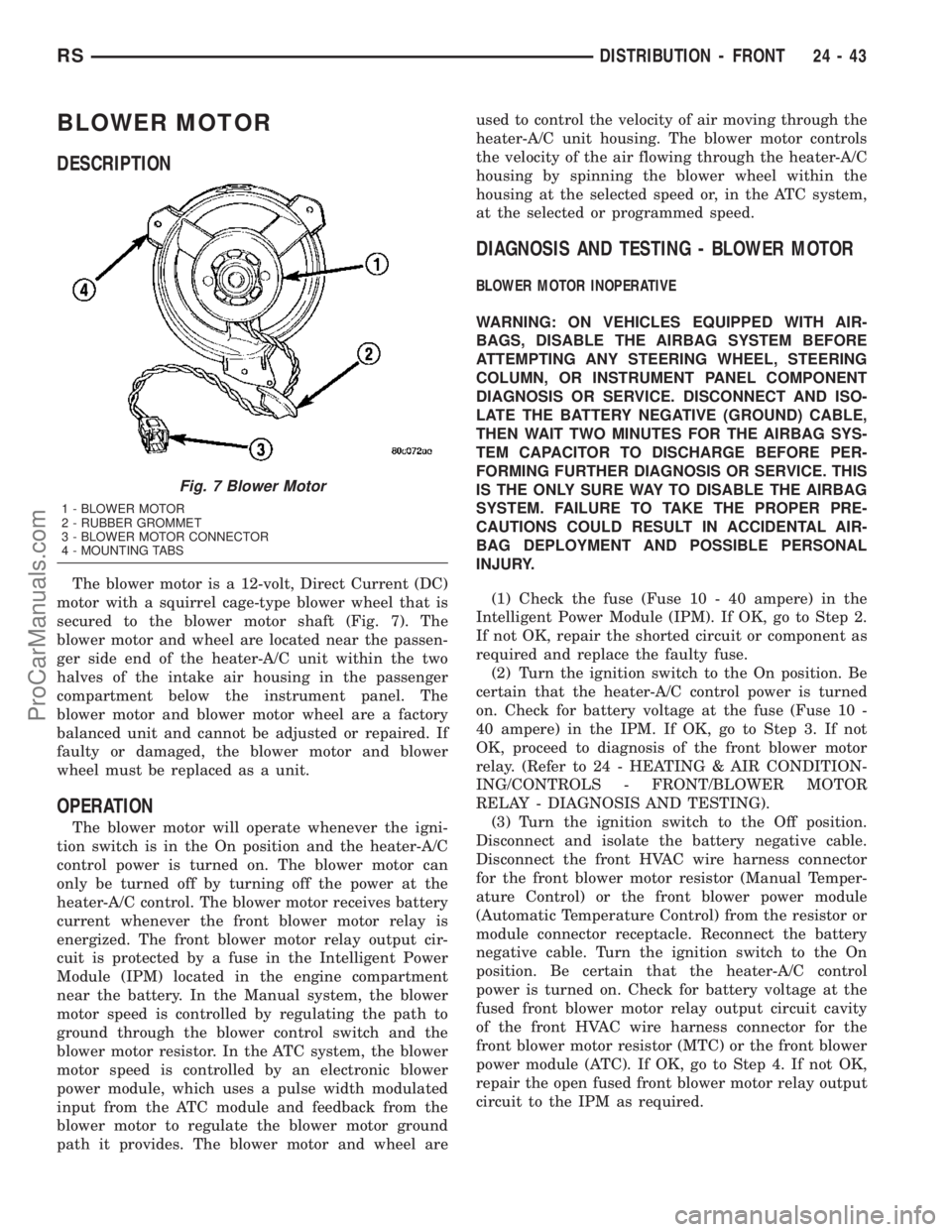
DESCRIPTION
The blower motor is a 12-volt, Direct Current (DC)
motor with a squirrel cage-type blower wheel that is
secured to the blower motor shaft (Fig. 7). The
blower motor and wheel are located near the passen-
ger side end of the heater-A/C unit within the two
halves of the intake air housing in the passenger
compartment below the instrument panel. The
blower motor and blower motor wheel are a factory
balanced unit and cannot be adjusted or repaired. If
faulty or damaged, the blower motor and blower
wheel must be replaced as a unit.
OPERATION
The blower motor will operate whenever the igni-
tion switch is in the On position and the heater-A/C
control power is turned on. The blower motor can
only be turned off by turning off the power at the
heater-A/C control. The blower motor receives battery
current whenever the front blower motor relay is
energized. The front blower motor relay output cir-
cuit is protected by a fuse in the Intelligent Power
Module (IPM) located in the engine compartment
near the battery. In the Manual system, the blower
motor speed is controlled by regulating the path to
ground through the blower control switch and the
blower motor resistor. In the ATC system, the blower
motor speed is controlled by an electronic blower
power module, which uses a pulse width modulated
input from the ATC module and feedback from the
blower motor to regulate the blower motor ground
path it provides. The blower motor and wheel areused to control the velocity of air moving through the
heater-A/C unit housing. The blower motor controls
the velocity of the air flowing through the heater-A/C
housing by spinning the blower wheel within the
housing at the selected speed or, in the ATC system,
at the selected or programmed speed.
DIAGNOSIS AND TESTING - BLOWER MOTOR
BLOWER MOTOR INOPERATIVE
WARNING: ON VEHICLES EQUIPPED WITH AIR-
BAGS, DISABLE THE AIRBAG SYSTEM BEFORE
ATTEMPTING ANY STEERING WHEEL, STEERING
COLUMN, OR INSTRUMENT PANEL COMPONENT
DIAGNOSIS OR SERVICE. DISCONNECT AND ISO-
LATE THE BATTERY NEGATIVE (GROUND) CABLE,
THEN WAIT TWO MINUTES FOR THE AIRBAG SYS-
TEM CAPACITOR TO DISCHARGE BEFORE PER-
FORMING FURTHER DIAGNOSIS OR SERVICE. THIS
IS THE ONLY SURE WAY TO DISABLE THE AIRBAG
SYSTEM. FAILURE TO TAKE THE PROPER PRE-
CAUTIONS COULD RESULT IN ACCIDENTAL AIR-
BAG DEPLOYMENT AND POSSIBLE PERSONAL
INJURY.
(1) Check the fuse (Fuse 10 - 40 ampere) in the
Intelligent Power Module (IPM). If OK, go to Step 2.
If not OK, repair the shorted circuit or component as
required and replace the faulty fuse.
(2) Turn the ignition switch to the On position. Be
certain that the heater-A/C control power is turned
on. Check for battery voltage at the fuse (Fuse 10 -
40 ampere) in the IPM. If OK, go to Step 3. If not
OK, proceed to diagnosis of the front blower motor
relay. (Refer to 24 - HEATING & AIR CONDITION-
ING/CONTROLS - FRONT/BLOWER MOTOR
RELAY - DIAGNOSIS AND TESTING).
(3) Turn the ignition switch to the Off position.
Disconnect and isolate the battery negative cable.
Disconnect the front HVAC wire harness connector
for the front blower motor resistor (Manual Temper-
ature Control) or the front blower power module
(Automatic Temperature Control) from the resistor or
module connector receptacle. Reconnect the battery
negative cable. Turn the ignition switch to the On
position. Be certain that the heater-A/C control
power is turned on. Check for battery voltage at the
fused front blower motor relay output circuit cavity
of the front HVAC wire harness connector for the
front blower motor resistor (MTC) or the front blower
power module (ATC). If OK, go to Step 4. If not OK,
repair the open fused front blower motor relay output
circuit to the IPM as required.
Fig. 7 Blower Motor
1 - BLOWER MOTOR
2 - RUBBER GROMMET
3 - BLOWER MOTOR CONNECTOR
4 - MOUNTING TABS
RSDISTRIBUTION - FRONT24-43
ProCarManuals.com
Page 2041 of 2177
(4) Turn the ignition switch to the Off position.
Disconnect and isolate the battery negative cable.
Disconnect the front blower motor pigtail wire con-
nector from the connector receptacle of the front
blower motor resistor (MTC) or the front blower
power module (ATC). Use jumper wires to connect a
battery and ground feeds to the blower motor pigtail
wire connector. The blower motor should operate. If
OK with MTC, proceed to diagnosis of the front
blower motor resistor. (Refer to 24 - HEATING & AIRCONDITIONING/CONTROLS - FRONT/BLOWER
MOTOR RESISTOR - DIAGNOSIS AND TESTING).
If OK with ATC, use a DRBIII scan tool to diagnose
the front blower power module. Refer to the appropri-
ate diagnostic information. If not OK with MTC or
ATC, replace the faulty front blower motor.
BLOWER MOTOR NOISE OR VIBRATION
Refer to the Blower Motor Noise/Vibration Diagno-
sis chart (Fig. 8).
24 - 44 DISTRIBUTION - FRONTRS
BLOWER MOTOR (Continued)
ProCarManuals.com
Page 2051 of 2177
OPERATION
The rear blower motor will operate whenever the
ignition switch is in the On position, the heater-A/C
control power is turned on, and the rear heater-A/C
system control switch on the front heater-A/C control
is not in the Off position. The blower motor can only
be turned off by turning off the rear system at the
front heater-A/C control. The blower motor receives
battery current whenever the rear blower motor
relay is energized. The rear blower motor relay out-
put circuit is protected by a fuse in the Intelligent
Power Module (IPM) located in the engine compart-
ment near the battery. In the MTC system, the
blower motor speed is controlled by regulating the
path to ground through the blower control switch and
the blower motor resistor. In the ATC system, the
blower motor speed is controlled by an electronic
blower power module, which uses a pulse width mod-
ulated input from the ATC module and feedback from
the blower motor to regulate the blower motor
ground path it provides. The blower motor and wheel
are used to control the velocity of air moving through
the rear heater-A/C unit housing. The blower motor
controls the velocity of the air flowing through the
rear heater-A/C housing by spinning the blower
wheel within the housing at the selected speed or, in
the ATC system, at the selected or programmed
speed.
DIAGNOSIS AND TESTING - BLOWER MOTOR
BLOWER MOTOR INOPERATIVE
(1) Check the fuse (Fuse 12 - 25 ampere) in the
Intelligent Power Module (IPM). If OK, go to Step 2.
If not OK, repair the shorted circuit or component as
required and replace the faulty fuse.
(2) Turn the ignition switch to the On position. Be
certain that the rear heater-A/C control power is
turned on. Check for battery voltage at the fuse
(Fuse 12 - 25 ampere) in the IPM. If OK, go to Step
3. If not OK, proceed to diagnosis of the rear blower
motor relay. (Refer to 24 - HEATING & AIR CONDI-
TIONING/CONTROLS - REAR/BLOWER MOTOR
RELAY - DIAGNOSIS AND TESTING).(3) Turn the ignition switch to the Off position.
Disconnect and isolate the battery negative cable.
Disconnect the rear HVAC wire harness connector for
the rear blower motor resistor (Manual Temperature
Control) or the rear blower power module (Automatic
Temperature Control) from the resistor or module
connector receptacle. Reconnect the battery negative
cable. Turn the ignition switch to the On position. Be
certain that the rear heater-A/C control power is
turned on. Check for battery voltage at the fused
rear blower motor relay output circuit cavity of the
rear HVAC wire harness connector for the rear
blower motor resistor (MTC) or the rear blower
power module (ATC). If OK, go to Step 4. If not OK,
repair the open fused front blower motor relay output
circuit to the IPM as required.
(4) Turn the ignition switch to the Off position.
Disconnect and isolate the battery negative cable.
Disconnect the rear blower motor pigtail wire connec-
tor from the take out and connector of the rear
HVAC wire harness (MTC) or the connector recepta-
cle of the rear blower power module (ATC). Use
jumper wires to connect a battery and ground feeds
to the blower motor pigtail wire connector. The
blower motor should operate. If OK with MTC, pro-
ceed to diagnosis of the rear blower motor resistor.
(Refer to 24 - HEATING & AIR CONDITIONING/
CONTROLS - REAR/BLOWER MOTOR RESISTOR -
DIAGNOSIS AND TESTING). If OK with ATC, use a
DRBIII scan tool to diagnose the rear blower power
module. Refer to the appropriate diagnostic informa-
tion. If not OK with MTC or ATC, replace the faulty
rear blower motor.
BLOWER MOTOR NOISE OR VIBRATION
Refer to the Blower Motor Noise/Vibration Diagno-
sis chart (Fig. 4).
24 - 54 DISTRIBUTION - REARRS
BLOWER MOTOR (Continued)
ProCarManuals.com