2003 CHRYSLER CARAVAN ignition
[x] Cancel search: ignitionPage 2103 of 2177
DIESEL SUPPLEMENTAL HEATER - DCHA - EXPORT
TABLE OF CONTENTS
page page
DIESEL SUPPLEMENTAL HEATER - DCHA -
EXPORT
DESCRIPTION........................106
OPERATION
OPERATION........................106
OPERATION - TWO ZONE ATC..........106
DIAGNOSIS AND TESTING - DIESEL
SUPPLEMENTAL HEATER - DCHA.......107
EXHAUST TUBE
REMOVAL............................107
INSTALLATION........................107
FUEL DOSING PUMP
DESCRIPTION........................108
OPERATION..........................108
REMOVAL............................108INSTALLATION........................108
FUEL LINE
STANDARD PROCEDURE - CLEANING.....109
REMOVAL............................109
INSTALLATION........................110
HEATER UNIT
REMOVAL............................111
INSTALLATION........................111
SUPPLEMENTAL DIESEL HEATER WIRING
REMOVAL............................112
INSTALLATION........................112
AIR INTAKE PIPE
REMOVAL............................112
INSTALLATION........................113
DIESEL SUPPLEMENTAL
HEATER - DCHA - EXPORT
DESCRIPTION
Vehicles equipped with the optional diesel engine
are also equipped with a supplemental heater unit.
This unit is mounted under the vehicle and operates
similar to an oil fired furnace. The heater burns
small amounts of fuel to provide additional heat to
the coolant. Coolant is routed from the engine, to the
supplemental heater, and then to the front heater
core. This provides additional heat to the passenger
compartment. The system is interfaced to the vehi-
cles on-board computer systems and DRB-III diag-
nostics.
The supplemental heater unit has a electronic con-
trol unit that monitors the heat output of the heater.
The heater operates at full load (5 kW), half load or
idle mode (no additional heat) depending on collant
temperature.
OPERATION
OPERATION
The supplemental heater unit is activated via the
temperature slide control or knob on the vehicle
HVAC control unit. If the control slide or knob is
moved to or above the upper set point the heater is
activated. The unit can operate in a full or partial
load range as well as an idle mode all dependent on
the engine coolant temperature. The heater unit willalso turn off if the HVAC temperature control is low-
ered to less than the lower set point. The heater unit
can take up to three minutes to completely shut
down when either the heater temperature is set
below the lower set point or the vehicle ignition is
shut down.
The supplemental heater only operates when the
engine is running, the mileage exceeds 8 kilometer (5
mph) and the fuel tank volume exceeds 1/8 of a tank.
The heater should start if the collant temperature is
below 40 degrees celsius (104 degrees F).
NOTE: Do not apply a strong vacuum directly on
the supplemtal heater exhaust line. Place the vac-
uum within 75 mm (3 inches) of the exhaust port.
Too strong of a vacuum can prevent the heater from
starting. The heater ECU monitors the supplemental
blower speed and combustion during its start-up.
OPERATION - TWO ZONE ATC
The Two Zone ATC control head will activate the
Supplemental Heater based on engine coolant tem-
perature and interior component settings. The unit
can operate in a full or partial load range as well as
an idle mode all dependent on the engine coolant
temperature. The unit will also turn off if the HVAC
temperature control setting is lowered to less than
the lower set point. The unit can take up to three
minutes to completely shut down when either the
heater temperature is set below the lower set point of
the vehicle ignition is shut down.
24 - 106 DIESEL SUPPLEMENTAL HEATER - DCHA - EXPORTRS
ProCarManuals.com
Page 2107 of 2177
INSTALLATION
WARNING: DO NOT OPERATE THE DCHA IN AN
ENCLOSED AREA SUCH AS A GARAGE THAT
DOES NOT HAVE EXHAUST VENTILATION FACILI-
TIES. ALWAYS VENT THE DCHA'S EXHAUST WHEN
OPERATING THE DCHA. FAILURE TO FOLLOW
THESE INSTRUCTIONS MAY RESULT IN PERSONAL
INJURY OR DEATH.
WARNING: ALLOW THE DCHA ASSEMBLY TO
COOL BEFORE PERFORMING A COMPONENT
INSPECTION/REPAIR/REPLACEMENT. FAILURE TO
FOLLOW THESE INSTRUCTIONS MAY RESULT IN
PERSONAL INJURY.
WARNING: VERIFY THAT ALL DCHA FUEL LINES
ARE SECURELY FASTENED TO THEIR RESPECTIVE
COMPONENTS BEFORE PERFORMING THIS PRO-
CEDURE.
NOTE: Verify that there is more than 1/8 of a tank of
fuel in the vehicle's fuel tank before performing this
procedure. Add fuel, if necessary.(1) Install heater fuel supply line to vehicle and
install in fuel line retainers
(2) Install fuel line connection at fuel tank and
tighten connection.
(3) Install fuel line at Dosing Pump and tighten
connection.
(4) Lower vehicle from lift.
NOTE: Failure to prime the Dosing Pump after
draining the DCHA fuel line will prevent DCHA
heater activation during the first attempt to start the
heater. This will also set a Diagnostic Trouble Code
(DCT) in the DCHA Control's memory. Do not per-
form the Dosing Pump Priming procedure if an
attempt was made to start the DCHA without prim-
ing the Dosing Pump first. This will put excess fuel
in the DCHA Heater Module and cause smoke to
emit from the DCHA exhaust pipe when heater acti-
vation occurs.
(5) Connect the DRBIIItto the Diagnostic Link
Connector.
(6) Turn the ignition to the on position.
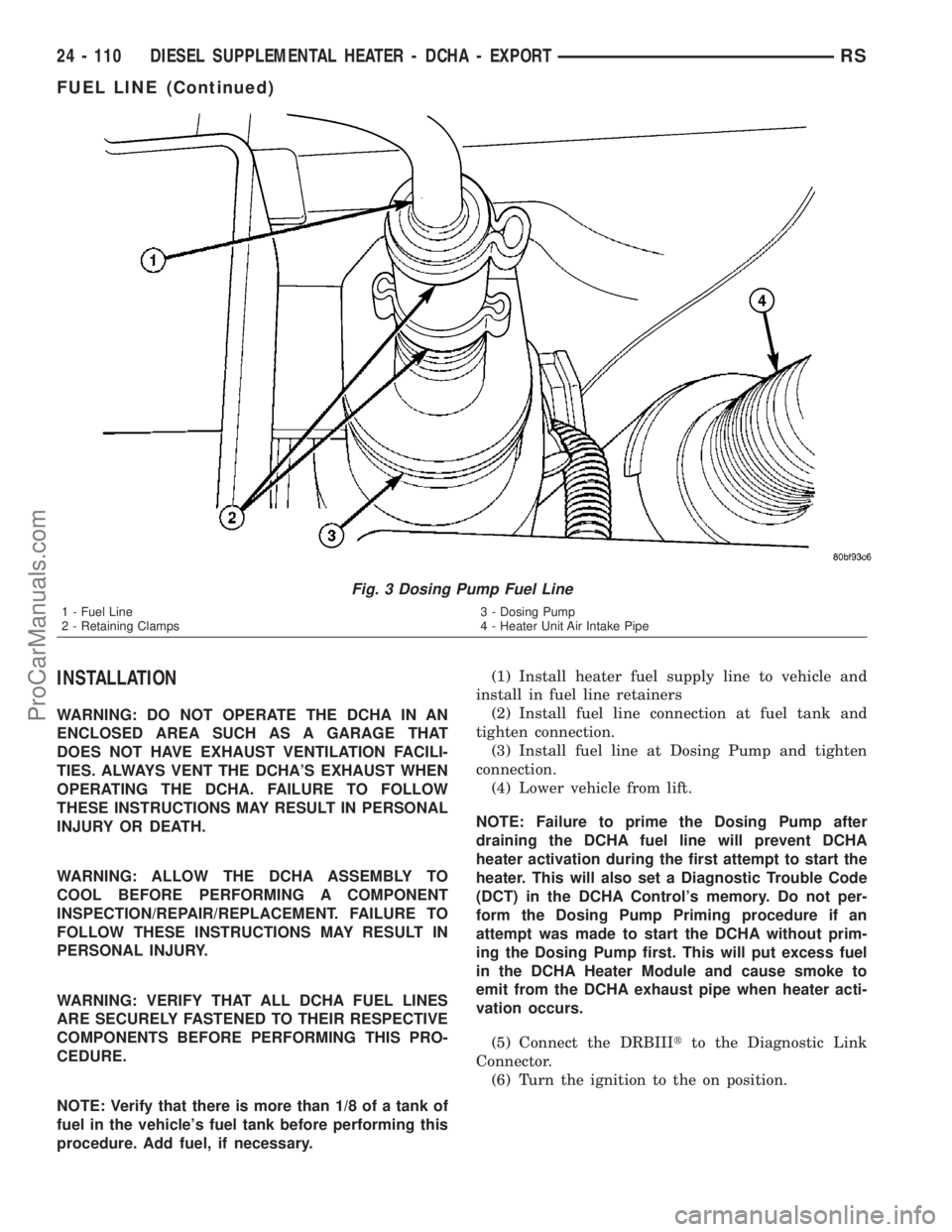
Fig. 3 Dosing Pump Fuel Line
1 - Fuel Line
2 - Retaining Clamps3 - Dosing Pump
4 - Heater Unit Air Intake Pipe
24 - 110 DIESEL SUPPLEMENTAL HEATER - DCHA - EXPORTRS
FUEL LINE (Continued)
ProCarManuals.com
Page 2113 of 2177
The following is a list of the monitored compo-
nents:
²Comprehensive Components
²Oxygen Sensor Monitor
²Oxygen Sensor Heater Monitor
²Catalyst Monitor
COMPREHENSIVE COMPONENTS
Along with the major monitors, OBD II requires
that the diagnostic system monitor any component
that could affect emissions levels. In many cases,
these components were being tested under OBD I.
The OBD I requirements focused mainly on testing
emissions-related components for electrical opens and
shorts.
However, OBD II also requires that inputs from
powertrain components to the PCM be tested for
rationality, and that outputs to powertrain compo-
nents from the PCM be tested forfunctionality.
Methods for monitoring the various Comprehensive
Component monitoring include:
(1) Circuit Continuity
²Open
²Shorted high
²Shorted to ground
(2) Rationality or Proper Functioning
²Inputs tested for rationality
²Outputs tested for functionality
NOTE: Comprehensive component monitors are
continuous. Therefore, enabling conditions do not
apply.
Input RationalityÐWhile input signals to the
PCM are constantly being monitored for electrical
opens and shorts, they are also tested for rationality.
This means that the input signal is compared against
other inputs and information to see if it makes sense
under the current conditions.
PCM sensor inputs that are checked for rationality
include:
²Manifold Absolute Pressure (MAP) Sensor
²Oxygen Sensor (O2S)
²Engine Coolant Temperature (ECT) Sensor
²Camshaft Position (CMP) Sensor
²Vehicle Speed Sensor
²Crankshaft Position (CKP) Sensor
²Intake/inlet Air Temperature (IAT) Sensor
²Throttle Position (TPS) Sensor
²Ambient Temperature Sensors
²Power Steering Switch
²Oxygen Sensor Heater
²Brake Switch
²Leak Detection Pump Switch or NVLD switch (if
equipped)
²P/N SwitchOutput FunctionalityÐPCM outputs are tested
for functionality in addition to testing for opens and
shorts. When the PCM provides a voltage to an out-
put component, it can verify that the command was
carried out by monitoring specific input signals for
expected changes. For example, when the PCM com-
mands the Idle Air Control (IAC) Motor to a specific
position under certain operating conditions, it expects
to see a specific (target) idle speed (RPM). If it does
not, it stores a DTC.
PCM outputs monitored for functionality include:
²Fuel Injectors
²Ignition Coils
²Idle Air Control
²Purge Solenoid
²EGR Solenoid (if equipped)
²LDP Solenoid or NVLD solenoid (if equipped)
²Radiator Fan Control
²Trans Controls
OXYGEN SENSOR (O2S) MONITOR
DESCRIPTIONÐEffective control of exhaust
emissions is achieved by an oxygen feedback system.
The most important element of the feedback system
is the O2S. The O2S is located in the exhaust path.
Once it reaches operating temperature 300É to 350ÉC
(572É to 662ÉF), the sensor generates a voltage that
is inversely proportional to the amount of oxygen in
the exhaust. When there is a large amount of oxygen
in the exhaust caused by a lean condition, the sensor
produces a low voltage, below 450 mV. When the oxy-
gen content is lower, caused by a rich condition, the
sensor produces a higher voltage, above 450mV (volt-
ages are offset by 2.5 volts on NGC vehicles).
The information obtained by the sensor is used to
calculate the fuel injector pulse width. The PCM is
programmed to maintain the optimum air/fuel ratio.
At this mixture ratio, the catalyst works best to
remove hydrocarbons (HC), carbon monoxide (CO)
and nitrous oxide (NOx) from the exhaust.
The O2S is also the main sensing element for the
EGR (if equipped), Catalyst and Fuel Monitors.
The O2S may fail in any or all of the following
manners:
²Slow response rate (Big Slope)
²Reduced output voltage (Half Cycle)
²Heater Performance
Slow Response Rate (Big Slope)ÐResponse rate
is the time required for the sensor to switch from
lean to rich signal output once it is exposed to a
richer than optimum A/F mixture or vice versa. As
the PCM adjusts the air/fuel ratio, the sensor must
be able to rapidly detect the change. As the sensor
ages, it could take longer to detect the changes in the
oxygen content of the exhaust gas. The rate of
change that an oxygen sensor experiences is called
25 - 2 EMISSIONS CONTROLRS
EMISSIONS CONTROL (Continued)
ProCarManuals.com
Page 2115 of 2177
OPERATIONÐThe Oxygen Sensor Heater Moni-
tor begins after the ignition has been turned OFF.
The PCM sends a 5 volt bias to the oxygen sensor
every 1.6 seconds. The PCM keeps it biased for 35
ms each time. As the sensor cools down, the resis-
tance increases and the PCM reads the increase in
voltage. Once voltage has increased to a predeter-
mined amount, higher than when the test started,
the oxygen sensor is cool enough to test heater oper-
ation.
When the oxygen sensor is cool enough, the PCM
energizes the ASD relay. Voltage to the O2 sensor
begins to increase the temperature. As the sensor
temperature increases, the internal resistance
decreases. The PCM continues biasing the 5 volt sig-
nal to the sensor. Each time the signal is biased, the
PCM reads a voltage decrease. When the PCM
detects a voltage decrease of a predetermined value
for several biased pulses, the test passes.
The heater elements are tested each time the
engine is turned OFF if all the enabling conditions
are met. If the monitor fails, the PCM stores a
maturing fault and a Freeze Frame is entered. If two
consecutive tests fail, a DTC is stored. Because the
ignition is OFF, the MIL is illuminated at the begin-
ning of the next key cycle.
Enabling ConditionsÐThe following conditions
must be met for the PCM to run the oxygen sensor
heater test:
²Engine run time of at least 3 minutes
²Engine run time at a predetermined speed
and throttle opening.
²Key OFF power down
²Battery voltage of at least 10 volts
²Sufficient Oxygen Sensor cool down
Pending ConditionsÐThere are not conditions or
situations that prompt conflict or suspension of test-
ing. The oxygen sensor heater test is not run pending
resolution of MIL illumination due to oxygen sensor
failure.
SuspendÐThere are no conditions which exist for
suspending the Heater Monitor.
CATALYST MONITOR
To comply with clean air regulations, vehicles are
equipped with catalytic converters. These converters
reduce the emission of hydrocarbons, oxides of nitro-
gen and carbon monoxide.
Normal vehicle miles or engine misfire can cause a
catalyst to decay. A meltdown of the ceramic core can
cause a reduction of the exhaust passage. This can
increase vehicle emissions and deteriorate engine
performance, driveability and fuel economy.
The catalyst monitor uses dual oxygen sensors
(O2S's) to monitor the efficiency of the converter. The
dual O2S strategy is based on the fact that as a cat-alyst deteriorates, its oxygen storage capacity and its
efficiency are both reduced. By monitoring the oxy-
gen storage capacity of a catalyst, its efficiency can
be indirectly calculated. The upstream O2S is used to
detect the amount of oxygen in the exhaust gas
before the gas enters the catalytic converter. The
PCM calculates the A/F mixture from the output of
the O2S. A low voltage indicates high oxygen content
(lean mixture). A high voltage indicates a low content
of oxygen (rich mixture).
When the upstream O2S detects a lean condition,
there is an abundance of oxygen in the exhaust gas.
A functioning converter would store this oxygen so it
can use it for the oxidation of HC and CO. As the
converter absorbs the oxygen, there will be a lack of
oxygen downstream of the converter. The output of
the downstream O2S will indicate limited activity in
this condition.
As the converter loses the ability to store oxygen,
the condition can be detected from the behavior of
the downstream O2S. When the efficiency drops, no
chemical reaction takes place. This means the con-
centration of oxygen will be the same downstream as
upstream. The output voltage of the downstream
O2S copies the voltage of the upstream sensor. The
only difference is a time lag (seen by the PCM)
between the switching of the O2S's.
To monitor the system, the number of lean-to-rich
switches of upstream and downstream O2S's is
counted. The ratio of downstream switches to
upstream switches is used to determine whether the
catalyst is operating properly. An effective catalyst
will have fewer downstream switches than it has
upstream switches i.e., a ratio closer to zero. For a
totally ineffective catalyst, this ratio will be one-to-
one, indicating that no oxidation occurs in the device.
The system must be monitored so that when cata-
lyst efficiency deteriorates and exhaust emissions
increase to over the legal limit, the MIL (check
engine lamp) will be illuminated.
Monitor OperationÐTo monitor catalyst effi-
ciency, the PCM expands the rich and lean switch
points of the heated oxygen sensor. With extended
switch points, the air/fuel mixture runs richer and
leaner to overburden the catalytic converter. Once
the test is started, the air/fuel mixture runs rich and
lean and the O2 switches are counted. A switch is
counted when an oxygen sensor signal goes from
below the lean threshold to above the rich threshold.
The number of Rear O2 sensor switches is divided by
the number of Front O2 sensor switches to determine
the switching ratio.
The test runs for 20 seconds. As catalyst efficiency
deteriorated over the life of the vehicle, the switch
rate at the downstream sensor approaches that of the
upstream sensor. If at any point during the test
25 - 4 EMISSIONS CONTROLRS
EMISSIONS CONTROL (Continued)
ProCarManuals.com
Page 2116 of 2177
period the switch ratio reaches a predetermined
value, a counter is incremented by one. The monitor
is enabled to run another test during that trip. When
the test fails 6 times, the counter increments to 3, a
malfunction is entered, and a Freeze Frame is stored,
the code is matured and the MIL is illuminated. If
the first test passes, no further testing is conducted
during that trip.
The MIL is extinguished after three consecutive
good trips. The good trip criteria for the catalyst
monitor is more stringent than the failure criteria. In
order to pass the test and increment one good trip,
the downstream sensor switch rate must be less than
45% of the upstream rate. The failure percentages
are 59% respectively.
Enabling ConditionsÐThe following conditions
must typically be met before the PCM runs the cat-
alyst monitor. Specific times for each parameter may
be different from engine to engine.
²Accumulated drive time
²Enable time
²Ambient air temperature
²Barometric pressure
²Catalyst warm-up counter
²Engine coolant temperature
²Vehicle speed
²MAP
²RPM
²Engine in closed loop
²Fuel level
Pending ConditionsÐ
²Misfire DTC
²Front Oxygen Sensor Response
²Front Oxygen Sensor Heater Monitor
²Front Oxygen Sensor Electrical
²Rear Oxygen Sensor Rationality (middle check)
²Rear Oxygen Sensor Heater Monitor
²Rear Oxygen Sensor Electrical
²Fuel System Monitor
²All TPS faults
²All MAP faults
²All ECT sensor faults
²Purge flow solenoid functionality
²Purge flow solenoid electrical
²All PCM self test faults
²All CMP and CKP sensor faults
²All injector and ignition electrical faults
²Idle Air Control (IAC) motor functionality
²Vehicle Speed Sensor
²Brake switch (auto trans only)
²Intake air temperature
ConflictÐThe catalyst monitor does not run if any
of the following are conditions are present:
²EGR Monitor in progress (if equipped)
²Fuel system rich intrusive test in progress
²EVAP Monitor in progress²Time since start is less than 60 seconds
²Low fuel level-less than 15 %
²Low ambient air temperature
²Ethanol content learn is taking place and the
ethanol used once flag is set
SuspendÐThe Task Manager does not mature a
catalyst fault if any of the following are present:
²Oxygen Sensor Monitor, Priority 1
²Oxygen Sensor Heater, Priority 1
²EGR Monitor, Priority 1 (if equipped)
²EVAP Monitor, Priority 1
²Fuel System Monitor, Priority 2
²Misfire Monitor, Priority 2
OPERATION - NON-MONITORED CIRCUITS
The PCM does not monitor all circuits, systems
and conditions that could have malfunctions causing
driveability problems. However, problems with these
systems may cause the PCM to store diagnostic trou-
ble codes for other systems or components. For exam-
ple, a fuel pressure problem will not register a fault
directly, but could cause a rich/lean condition or mis-
fire. This could cause the PCM to store an oxygen
sensor or misfire diagnostic trouble code.
The major non-monitored circuits are listed below
along with examples of failures modes that do not
directly cause the PCM to set a DTC, but for a sys-
tem that is monitored.
FUEL PRESSURE
The fuel pressure regulator controls fuel system
pressure. The PCM cannot detect a clogged fuel
pump inlet filter, clogged in-line fuel filter, or a
pinched fuel supply or return line. However, these
could result in a rich or lean condition causing the
PCM to store an oxygen sensor, fuel system, or mis-
fire diagnostic trouble code.
SECONDARY IGNITION CIRCUIT
The PCM cannot detect an inoperative ignition coil,
fouled or worn spark plugs, ignition cross firing, or
open spark plug cables. The misfire will however,
increase the oxygen content in the exhaust, deceiving
the PCM in to thinking the fuel system is too lean.
Also see misfire detection.
CYLINDER COMPRESSION
The PCM cannot detect uneven, low, or high engine
cylinder compression. Low compression lowers O2
content in the exhaust. Leading to fuel system, oxy-
gen sensor, or misfire detection fault.
EXHAUST SYSTEM
The PCM cannot detect a plugged, restricted or
leaking exhaust system. It may set a EGR (if
equipped) or Fuel system or O2S fault.
RSEMISSIONS CONTROL25-5
EMISSIONS CONTROL (Continued)
ProCarManuals.com
Page 2117 of 2177
FUEL INJECTOR MECHANICAL MALFUNCTIONS
The PCM cannot determine if a fuel injector is
clogged, the needle is sticking or if the wrong injector
is installed. However, these could result in a rich or
lean condition causing the PCM to store a diagnostic
trouble code for either misfire, an oxygen sensor, or
the fuel system.
EXCESSIVE OIL CONSUMPTION
Although the PCM monitors engine exhaust oxygen
content when the system is in closed loop, it cannot
determine excessive oil consumption.
THROTTLE BODY AIR FLOW
The PCM cannot detect a clogged or restricted air
cleaner inlet or filter element.
VACUUM ASSIST
The PCM cannot detect leaks or restrictions in the
vacuum circuits of vacuum assisted engine control
system devices. However, these could cause the PCM
to store a MAP sensor diagnostic trouble code and
cause a high idle condition.
PCM SYSTEM GROUND
The PCM cannot determine a poor system ground.
However, one or more diagnostic trouble codes may
be generated as a result of this condition. The mod-
ule should be mounted to the body at all times,
including when diagnostics are performed.
PCM CONNECTOR ENGAGEMENT
The PCM may not be able to determine spread or
damaged connector pins. However, it might store
diagnostic trouble codes as a result of spread connec-
tor pins.
DESCRIPTION - MONITORED SYSTEMS
There are new electronic circuit monitors that
check fuel, emission, engine and ignition perfor-
mance. These monitors use information from various
sensor circuits to indicate the overall operation of the
fuel, engine, ignition and emission systems and thus
the emissions performance of the vehicle.
The fuel, engine, ignition and emission systems
monitors do not indicate a specific component prob-
lem. They do indicate that there is an implied prob-
lem within one of the systems and that a specific
problem must be diagnosed.
If any of these monitors detect a problem affecting
vehicle emissions, the Malfunction Indicator (Check
Engine) Lamp will be illuminated. These monitors
generate Diagnostic Trouble Codes that can be dis-
played with the a DRBIIItscan tool.
The following is a list of the system monitors:
²EGR Monitor (if equipped)²Misfire Monitor
²Fuel System Monitor
²Oxygen Sensor Monitor
²Oxygen Sensor Heater Monitor
²Catalyst Monitor
²Evaporative System Leak Detection Monitor (if
equipped)
Following is a description of each system monitor,
and its DTC.
Refer to the appropriate Powertrain Diagnos-
tics Procedures manual for diagnostic proce-
dures.
OXYGEN SENSOR (O2S) MONITOR
Effective control of exhaust emissions is achieved
by an oxygen feedback system. The most important
element of the feedback system is the O2S. The O2S
is located in the exhaust path. Once it reaches oper-
ating temperatures of 300É to 350ÉC (572É to 662ÉF),
the sensor generates a voltage that is inversely pro-
portional to the amount of oxygen in the exhaust.
The information obtained by the sensor is used to
calculate the fuel injector pulse width. The PCM is
programmed to maintain the optimum air/fuel ratio.
At this mixture ratio, the catalyst works best to
remove hydrocarbons (HC), carbon monoxide (CO)
and nitrous oxide (NOx) from the exhaust.
The O2S is also the main sensing element for the
EGR (if equipped), Catalyst and Fuel Monitors.
The O2S may fail in any or all of the following
manners:
²Slow response rate
²Reduced output voltage
²Dynamic shift
²Shorted or open circuits
Response rate is the time required for the sensor to
switch from lean to rich once it is exposed to a richer
than optimum A/F mixture or vice versa. As the sen-
sor starts malfunctioning, it could take longer to
detect the changes in the oxygen content of the
exhaust gas.
The output voltage of the O2S ranges from 0 to 1
volt (voltages are offset by 2.5 volts on NGC vehi-
cles). A good sensor can easily generate any output
voltage in this range as it is exposed to different con-
centrations of oxygen. To detect a shift in the A/F
mixture (lean or rich), the output voltage has to
change beyond a threshold value. A malfunctioning
sensor could have difficulty changing beyond the
threshold value.
OXYGEN SENSOR HEATER MONITOR
If there is an oxygen sensor (O2S) DTC as well as
a O2S heater DTC, the O2S heater fault MUST be
repaired first. After the O2S fault is repaired, verify
that the heater circuit is operating correctly.
25 - 6 EMISSIONS CONTROLRS
EMISSIONS CONTROL (Continued)
ProCarManuals.com
Page 2120 of 2177
OPERATION
OPERATION - SYSTEM
The Powertrain Control Module (PCM) monitors
many different circuits in the fuel injection, ignition,
emission and engine systems. If the PCM senses a
problem with a monitored circuit often enough to
indicate an actual problem, it stores a Diagnostic
Trouble Code (DTC) in the PCM's memory. If the
code applies to a non-emissions related component or
system, and the problem is repaired or ceases to
exist, the PCM cancels the code after 40 warmup
cycles. Diagnostic trouble codes that affect vehicle
emissions illuminate the Malfunction Indicator Lamp
(MIL). Refer to Malfunction Indicator Lamp in this
section.
Certain criteria must be met before the PCM
stores a DTC in memory. The criteria may be a spe-
cific range of engine RPM, engine temperature,
and/or input voltage to the PCM.
The PCM might not store a DTC for a monitored
circuit even though a malfunction has occurred. This
may happen because one of the DTC criteria for the
circuit has not been met.For example, assume the
diagnostic trouble code criteria requires the PCM to
monitor the circuit only when the engine operates
between 750 and 2000 RPM. Suppose the sensor's
output circuit shorts to ground when engine operates
above 2400 RPM (resulting in 0 volt input to the
PCM). Because the condition happens at an engine
speed above the maximum threshold (2000 rpm), the
PCM will not store a DTC.
There are several operating conditions for which
the PCM monitors and sets DTC's. Refer to Moni-
tored Systems, Components, and Non-Monitored Cir-
cuits in this section.
NOTE: Various diagnostic procedures may actually
cause a diagnostic monitor to set a DTC. For
instance, pulling a spark plug wire to perform a
spark test may set the misfire code. When a repair
is completed and verified, use the DRBIIITscan tool
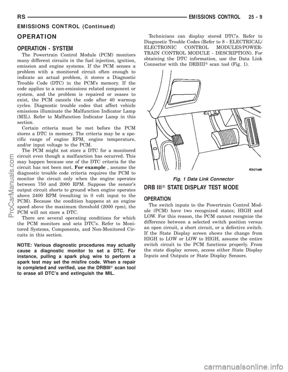
to erase all DTC's and extinguish the MIL.Technicians can display stored DTC's. Refer to
Diagnostic Trouble Codes (Refer to 8 - ELECTRICAL/
ELECTRONIC CONTROL MODULES/POWER-
TRAIN CONTROL MODULE - DESCRIPTION). For
obtaining the DTC information, use the Data Link
Connector with the DRBIIItscan tool (Fig. 1).
DRB IIITSTATE DISPLAY TEST MODE
OPERATION
The switch inputs to the Powertrain Control Mod-
ule (PCM) have two recognized states; HIGH and
LOW. For this reason, the PCM cannot recognize the
difference between a selected switch position versus
an open circuit, a short circuit, or a defective switch.
If the State Display screen shows the change from
HIGH to LOW or LOW to HIGH, assume the entire
switch circuit to the PCM functions properly. From
the state display screen, access either State Display
Inputs and Outputs or State Display Sensors.
Fig. 1 Data Link Connector
RSEMISSIONS CONTROL25-9
EMISSIONS CONTROL (Continued)
ProCarManuals.com
Page 2145 of 2177
CENTER - DESCRIPTION, ELECTRONIC
VEHICLE INFO.......................8M-6
CENTER - DIAGNOSIS AND TESTING,
ELECTRONIC VEHICLE INFORMATION.....8M-7
CENTER - INSTALLATION, ELECTRONIC
VEHICLE INFO.......................8M-9
CENTER - OPERATION, ELECTRONIC
VEHICLE INFO.......................8M-7
CENTER - REMOVAL, ELECTRONIC
VEHICLE INFO.......................8M-9
CENTER BEZEL - INSTALLATION,
INSTRUMENT PANEL..................23-67
CENTER BEZEL - REMOVAL,
INSTRUMENT PANEL..................23-67
CENTER BEZEL OUTLETS -
INSTALLATION.......................24-42
CENTER BEZEL OUTLETS - REMOVAL....24-40
CENTER CONSOLE LAMP SWITCH -
INSTALLATION.......................8L-26
CENTER CONSOLE LAMP SWITCH -
REMOVAL..........................8L-26
CENTER HIGH MOUNTED STOP LAMP -
INSTALLATION........................8L-6
CENTER HIGH MOUNTED STOP LAMP -
REMOVAL...........................8L-6
CENTER HIGH MOUNTED STOP LAMP
UNIT - INSTALLATION..................8L-7
CENTER HIGH MOUNTED STOP LAMP
UNIT - REMOVAL.....................8L-6
CENTER HINGE - INSTALLATION.........23-24
CENTER HINGE - REMOVAL............23-24
CENTER PROGRAMMING - STANDARD
PROCEDURE, ELECTRONIC VEHICLE
INFORMATION.......................8M-7
CENTER STRIKER - INSTALLATION.......23-27
CENTER STRIKER - REMOVAL..........23-27
CENTERING - STANDARD PROCEDURE,
CLOCK SPRING.......................8O-4
CERTIFICATION LABEL - DESCRIPTION,
VEHICLE SAFETY..................Intro.-11
CHAIN AND CAMSHAFT SPROCKET -
INSTALLATION, TIMING................9-157
CHAIN AND CAMSHAFT SPROCKET -
REMOVAL, TIMING...................9-156
CHAIN COVER - INSTALLATION, TIMING . . 9-155
CHAIN COVER - REMOVAL, TIMING......9-153
CHAIN WEAR - STANDARD PROCEDURE,
MEASURING TIMING..................9-153
CHANGE - STANDARD PROCEDURE,
DIFFERENTIAL ASSEMBLY FLUID.........3-40
CHANGE - STANDARD PROCEDURE,
ENGINE OIL AND FILTER...........9-137,9-53
CHANGE - STANDARD PROCEDURE,
OVERRUNNING CLUTCH HOUSING
FLUID..............................3-41
CHANGE - STANDARD PROCEDURE, PTU
FLUID..............................21-5
CHANGER - DESCRIPTION, CD...........8A-7
CHANGER - INSTALLATION, CD..........8A-8
CHANGER - OPERATION, CD.............8A-7
CHANGER - REMOVAL, CD..............8A-8
CHANNEL - INSTALLATION, WATER.....23-118
CHANNEL - REMOVAL, WATER.........23-118
CHARGE - STANDARD PROCEDURE,
REFRIGERANT SYSTEM
...............24-88
CHARGE LEVEL - DIAGNOSIS AND
TESTING, REFRIGERANT SYSTEM
.......24-85
CHARGING - STANDARD PROCEDURE,
CONVENTIONAL BATTERY
..............8F-11
CHARGING - STANDARD PROCEDURE,
SPIRAL PLATE BATTERY
...............8F-10
CHARGING SYSTEM - DESCRIPTION
.....8F-20
CHARGING SYSTEM - OPERATION
.......8F-20
CHARTS - DIAGNOSIS AND TESTING,
STEERING SYSTEM DIAGNOSIS
..........19-3
CHARTS - SPECIFICATIONS, COLOR
CODE
..............................23-83
CHATTER COMPLAINTS - DIAGNOSIS
AND TESTING, CLUTCH
.................6-6
CHECK - DIAGNOSIS AND TESTING,
COOLING SYSTEM FLOW
................7-3
CHECK - DIAGNOSIS AND TESTING,
EXHAUST SYSTEM RESTRICTION
.........11-2
CHECK - STANDARD PROCEDURE,
COOLANT LEVEL
.......................7-5
CHECK - STANDARD PROCEDURE,
ENGINE OIL LEVEL
...................9-137CHECK - STANDARD PROCEDURE, FLUID
LEVEL.............................21-71
CHECK, STANDARD PROCEDURE -
ENGINE OIL LEVEL....................9-53
CHECK, STANDARD PROCEDURE - FLUID
LEVEL AND CONDITION..............21-201
CHECK STRAP - INSTALLATION.........23-15
CHECK STRAP - REMOVAL.............23-15
CHECKING - STANDARD PROCEDURE,
BRAKE FLUID LEVEL...................5-32
CHECKING - STANDARD PROCEDURE,
POWER STEERING FLUID LEVEL........19-44
CHECKING BATTERY ELECTROLYTE
LEVEL - STANDARD PROCEDURE........8F-14
CHECKING ENGINE OIL PRESSURE -
DIAGNOSIS AND TESTING..............9-52
CHECKING POWER STEERING BELT
TENSION - STANDARD PROCEDURE.......7-8
CHILD SEAT - INSTALLATION, QUAD.....23-88
CHILD SEAT - REMOVAL, QUAD.........23-88
CHILD SEAT MODULE, BENCH SEAT -
REMOVAL..........................23-86
CHIME SYSTEM - DIAGNOSIS AND
TESTING............................8B-1
CHIME/BUZZER - DESCRIPTION..........8B-1
CHIME/BUZZER - OPERATION............8B-1
CHIME/BUZZER - WARNING.............8B-1
CHIME/THERMISTOR - DESCRIPTION....8N-10
CHIME/THERMISTOR - INSTALLATION....8N-10
CHIME/THERMISTOR - OPERATION......8N-10
CHIME/THERMISTOR - REMOVAL.......8N-10
CHIRP PREFERENCE - STANDARD
PROCEDURE, HORN..................8N-42
CIRCUIT - DIAGNOSIS AND TESTING,
AMBIENT TEMPERATURE SENSOR......8M-12
CIRCUIT FUNCTIONS - DESCRIPTION . . 8W-01-6
CIRCUIT INFORMATION - DESCRIPTION . 8W-01-5
CIRCUIT RESISTANCE TEST -
DIAGNOSIS AND TESTING, FEED........8F-32
CIRCUIT TEST - DIAGNOSIS AND
TESTING, CONTROL..................8F-30
CIRCUIT TEST - DIAGNOSIS AND
TESTING, FEED......................8F-33
CIRCUITS - OPERATION, NON-
MONITORED.........................25-5
CIRCUITS AND VALVES - OPERATION,
HYDRAULIC..........................5-83
CLAMP - STANDARD PROCEDURE,
HOSES..............................14-6
CLAMPS - DESCRIPTION, FUEL
LINES/HOSES........................14-6
CLAMPS - DESCRIPTION, HOSE...........7-1
CLAMPS - OPERATION, HOSE.............7-2
CLEAN, CLEANING...................21-114
CLEARANCE - STANDARD PROCEDURE,
MEASURING CONNECTING ROD
BEARING...........................9-120
CLEARANCE USING PLASTIGAGE -
STANDARD PROCEDURE, MEASURING
BEARING........................9-12,9-84
CLOCK SPRING - DESCRIPTION..........8O-4
CLOCK SPRING - INSTALLATION.........8O-5
CLOCK SPRING - OPERATION...........8O-4
CLOCK SPRING - REMOVAL.............8O-4
CLOCK SPRING CENTERING -
STANDARD PROCEDURE...............8O-4
CLUSTER - DESCRIPTION, INSTRUMENT . . . 8J-1
CLUSTER - OPERATION, INSTRUMENT.....8J-1
CLUSTER BEZEL - INSTALLATION
........23-62
CLUSTER BEZEL - REMOVAL
...........23-62
CLUSTER DIAGNOSIS - DIAGNOSIS AND
TESTING
............................8J-2
CLUSTER ILLUMINATION LAMPS -
INSTALLATION
.......................8L-26
CLUSTER ILLUMINATION LAMPS -
REMOVAL
..........................8L-26
CLUSTER LENS - INSTALLATION
........8J-10
CLUSTER LENS - REMOVAL
............8J-10
CLUTCH - DESCRIPTION
.................6-1
CLUTCH - DESCRIPTION, BI-
DIRECTIONAL OVERRUNNING
...........3-34
CLUTCH - DESCRIPTION, COMPRESSOR
. . 24-16
CLUTCH - OPERATION, BI-DIRECTIONAL
OVERRUNNING
.......................3-36
CLUTCH - OPERATION, COMPRESSOR
....24-17
CLUTCH AIR GAP - STANDARD
PROCEDURE, COMPRESSOR
...........24-17CLUTCH AIR PRESSURE TESTS -
DIAGNOSIS AND TESTING............21-122
CLUTCH ASSEMBLY - ASSEMBLY, INPUT . 21-216
CLUTCH ASSEMBLY - DISASSEMBLY,
INPUT............................21-208
CLUTCH ASSY - 2.4L GAS -
INSTALLATION, MODULAR..............6-11
CLUTCH ASSY - 2.4L GAS - REMOVAL,
MODULAR...........................6-11
CLUTCH BREAK-IN - STANDARD
PROCEDURE, COMPRESSOR...........24-17
CLUTCH CHATTER COMPLAINTS -
DIAGNOSIS AND TESTING...............6-6
CLUTCH COIL - DIAGNOSIS AND
TESTING, COMPRESSOR...............24-20
CLUTCH COVER AND DISC RUNOUT -
DIAGNOSIS AND TESTING...............6-6
CLUTCH DISC AND PRESSURE PLATE -
2.5L TD - INSTALLATION...............6-12
CLUTCH DISC AND PRESSURE PLATE -
2.5L TD - REMOVAL...................6-11
CLUTCH HOUSING FLUID CHANGE -
STANDARD PROCEDURE,
OVERRUNNING.......................3-41
CLUTCH PEDAL INTERLOCK SWITCH -
INSTALLATION........................6-14
CLUTCH PEDAL INTERLOCK SWITCH -
REMOVAL...........................6-13
CLUTCH PEDAL UPSTOP SWITCH -
INSTALLATION........................6-16
CLUTCH PEDAL UPSTOP SWITCH -
REMOVAL...........................6-15
CLUTCH RELAY - DESCRIPTION,
COMPRESSOR........................24-21
CLUTCH RELAY - DIAGNOSIS AND
TESTING, COMPRESSOR...............24-22
CLUTCH RELAY - INSTALLATION,
COMPRESSOR.......................24-22
CLUTCH RELAY - OPERATION,
COMPRESSOR.......................24-21
CLUTCH RELAY - REMOVAL,
COMPRESSOR.......................24-22
CLUTCH RELEASE LEVER AND BEARING
- INSTALLATION.......................6-7
CLUTCH RELEASE LEVER AND BEARING
- REMOVAL...........................6-6
CLUTCH SYSTEM - DIAGNOSIS AND
TESTING.............................6-3
CLUTCH/COIL - INSPECTION,
COMPRESSOR.......................24-18
CLUTCHES - DESCRIPTION, DRIVING....21-190
CLUTCHES - DESCRIPTION, HOLDING . . . 21-207
CLUTCHES - OPERATION, DRIVING.....21-190
CLUTCHES - OPERATION, HOLDING.....21-207
COAT/CLEARCOAT FINISH -
DESCRIPTION, BASE..................23-84
CODE - DESCRIPTION, PAINT...........23-84
CODE CHARTS - SPECIFICATIONS,
COLOR.............................23-83
CODE PLATE - DESCRIPTION, BODY....Intro.-1
CODES - STANDARD PROCEDURE,
ERASING TRANSMITTER..............8M-11
CODES - STANDARD PROCEDURE,
OBTAINING DIAGNOSTIC TROUBLE......8E-15
CODES - STANDARD PROCEDURE,
SETTING TRANSMITTER..............8M-11
COIL - DESCRIPTION, IGNITION
..........8I-6
COIL - DIAGNOSIS AND TESTING,
COMPRESSOR CLUTCH
...............24-20
COIL - OPERATION, IGNITION
............8I-6
COLLAR - INSTALLATION, STRUCTURAL
. . . 9-48
COLLAR - REMOVAL, STRUCTURAL
.......9-47
COLOR CODE CHARTS -
SPECIFICATIONS
.....................23-83
COLUMN - DESCRIPTION, STEERING
.....19-10
COLUMN - DIAGNOSIS AND TESTING,
STEERING
..........................19-12
COLUMN COVER - INSTALLATION,
LOWER STEERING
...................23-69
COLUMN COVER - INSTALLATION, OVER
STEERING
..........................23-69
COLUMN COVER - REMOVAL, LOWER
STEERING
..........................23-69
COLUMN COVER - REMOVAL, OVER
STEERING
..........................23-69
COLUMN COVER BACKING PLATE -
INSTALLATION, STEERING
.............23-69
6 INDEXRS
Description Group-Page Description Group-Page Description Group-Page
ProCarManuals.com