2003 BMW Z4 2.5I traction control
[x] Cancel search: traction controlPage 14 of 106

Overview
14
Indicator and warning
lamps
Technology that monitors itself
Indicator and warning lamps that are iden-
tified by
+ are tested for proper functioning
whenever the ignition key is turned. They
each light up once for different periods of
time.
If a fault should occur in one of these sys-
tems, the corresponding lamp does not go
out after the engine is started or it lights up
again while the vehicle is moving. The indi-
cated pages provide information on what
measures to take.
Please fasten safety belts
+31
Airbags
+33
Battery charge current
+87
Engine oil pressure/Engine oil level/
Engine oil sensor
+79
Parking brake/Chassis control sys-
tem/Dynamic Brake Control/Brake
fluid
+39/ 51/ 52/ 81
Brake warning lamp for Canadian
models
Antilock Brake System ABS/Chas-
sis control system
+53/ 51
Antilock Brake System ABS/Chas-
sis control system for Canadian
modelsDynamic Stability Control DSC
+51
Dynamic Traction Control DTC
+51
Flat Tire Monitor
+53
Automatic transmission
+41
Brake pads
+66
Add coolant80
Check Gas Cap
+
Service engine soon +83
Service engine soon
+
warning lamp for Canadian
models.
Defective bulbs45
Turn signal indicators42
Fog lamps46
Headlamp flasher/
High beams42/ 46
Page 39 of 106
At a glance
Controls
Driving tips
Mobility
Reference
39
the ignition key immediately when the
engine starts.<
Extended starting attempts, charac-
terized by excessively frequent or
long periods with the starter engaged, can
damage the catalytic converter.<
If the engine fails to start on the first
attempt – if it is very hot or cold, for
instance:
>Press the accelerator pedal halfway
down.
Cold starts at very low temperatures –
starting at approx. +57 / –156
>Press the accelerator pedal halfway
down while engaging the starter
>On the first start attempt, engage the
starter for a longer period –
approx. 10 seconds.
Manual transmission
1.Engage the parking brake
2.Gearshift lever in idling position
3.Depress clutch pedal
4.Start the engine.
Automatic transmission
1.Depress footbrake
2.Place selector lever in position P or N
3.Start the engine.
Before leaving the vehicle with the
engine running, place the selector
lever in position P and pull the parking
brake.
Do not leave the vehicle unattended with
the engine running. An unattended vehicle
with a running engine poses a safety haz-
ard.<
Switching off the engine
Do not remove the ignition key while
the vehicle is still moving. If you did so,
the steering lock would engage when the
steering wheel is turned.
When you leave the vehicle, always remove
the ignition key and engage the steering lock.
Always engage the parking brake when park-
ing on downhill roads.<
Manual transmission
Turn the ignition key to position 1 or 0.
Automatic transmission
Place the selector lever in position P and
turn the ignition key to position 1 or 0.
Parking brake
The parking brake is designed primarily to
prevent the vehicle from rolling when
parked. It operates against the rear wheels.
The brake warning lamp lights up
when the parking brake is engaged;
if you start driving, an acoustic sig-
nal is heard as well.
Brake warning lamp for Canadian
models
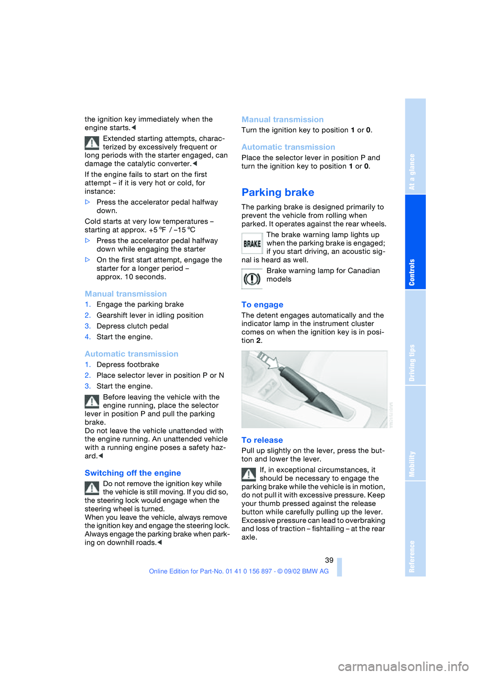
To engage
The detent engages automatically and the
indicator lamp in the instrument cluster
comes on when the ignition key is in posi-
tion 2.
To release
Pull up slightly on the lever, press the but-
ton and lower the lever.
If, in exceptional circumstances, it
should be necessary to engage the
parking brake while the vehicle is in motion,
do not pull it with excessive pressure. Keep
your thumb pressed against the release
button while carefully pulling up the lever.
Excessive pressure can lead to overbraking
and loss of traction – fishtailing – at the rear
axle.
Page 51 of 106
At a glance
Controls
Driving tips
Mobility
Reference
51
Technology for safety and driving
convenience
Dynamic Stability Control
DSC
The concept
DSC maintains vehicle stability, even in
critical driving situations.
The DSC is operational every time you start
the engine.
For additional details on the system
and the various functions, please
refer to the "Technology" brochure.<
Indicator lamps
The indicator lamps in the instrument clus-
ter go out shortly after you switch on the
ignition.
Dynamic Stability Control DSC indi-
cator lamp flashes:
The system is active and governs
drive torque and braking intervention.
The indicator lamp stays lit:
Dynamic Stability Control DSC and
Dynamic Traction Control DTC have been
switched off via the button.
Dynamic Traction Control DTC indi-
cator lamp lights up permanently:
DTC has been deactivated via the
DSC button.
Dynamic Stability Control DSC indi-
cator lamp flashes:
Dynamic Traction Control DTC indi-
cator lamp lights up permanently:
DTC is actively regulating drive
torque and braking intervention.
Interventions to increase stability are
being performed to a limited degree
only.
warning lamp for Dynamic Brake
Control DBC light up continuously:
Dynamic Stability Control DSC,
Dynamic Traction Control DTC and
Dynamic Brake Control DBC are malfunc-
tioning.
Have the system repaired at your BMW
center.
Indicator and warning lamps for
Canadian models.
The vehicle remains completely oper-
ational without the DSC, DTC and
DBC functions.<
In the event of a malfunction, please see
your BMW center.
If the brake warning lamp comes on
together with the yellow indicator
lamps for the Antilock Brake Sys-
tem ABS and the Dynamic Stability
Control DSC:
The entire ABS and DSC control
system has failed. Continue driving
cautiously and defensively. Avoid
hard brake applications. Please have the
system checked by your BMW center as
soon as possible.
ABS and DSC indicator and warn-
ing lamps for Canadian models.
Page 52 of 106
Technology for safety and driving convenience
52 For more information on the various
systems, refer to the "Technology"
brochure.<
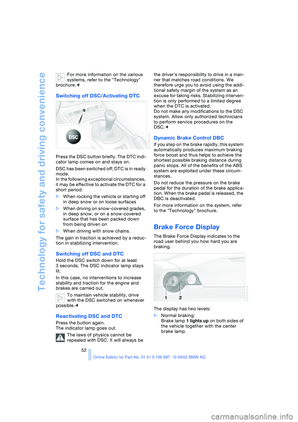
Switching off DSC/Activating DTC
Press the DSC button briefly. The DTC indi-
cator lamp comes on and stays on.
DSC has been switched off; DTC is in ready
mode.
In the following exceptional circumstances,
it may be effective to activate the DTC for a
short period:
>When rocking the vehicle or starting off
in deep snow or on loose surfaces
>When driving on snow-covered grades,
in deep snow, or on a snow-covered
surface that has been packed down
from being driven on
>When driving with snow chains.
The gain in traction is achieved by a reduc-
tion in stabilizing intervention.
Switching off DSC and DTC
Hold the DSC switch down for at least
3 seconds. The DSC indicator lamp stays
lit.
In this case, no interventions to increase
stability and traction for the engine and
brakes are carried out.
To maintain vehicle stability, drive
with the DSC switched on whenever
possible.<
Reactivating DSC and DTC
Press the button again.
The indicator lamp goes out.
The laws of physics cannot be
repealed with DSC. It will always be the driver's responsibility to drive in a man-
ner that matches road conditions. We
therefore urge you to avoid using the addi-
tional safety margin of the system as an
excuse for taking risks. Stabilizing interven-
tion is only performed to a limited degree
when the DTC is activated.
Do not make any modifications to the DSC
system. Allow only authorized technicians
to perform service procedures on the
DSC.<
Dynamic Brake Control DBC
If you step on the brake rapidly, this system
automatically produces maximum braking
force boost and thus helps to achieve the
shortest possible braking distance during
panic stops. All of the benefits of the ABS
system are exploited under these circum-
stances.
Do not reduce the pressure on the brake
pedal for the duration of the brake applica-
tion. When the brake pedal is released, the
DBC is deactivated.
For more information on the system, refer
to the "Technology" brochure.
Brake Force Display
The Brake Force Display indicates to the
road user behind you how hard you are
braking.
The display has two levels:
>Normal braking:
Brake lamp 1 lights up on both sides of
the vehicle together with the center
brake lamp.
Page 64 of 106
Special operating instructions
64
Special operating instructions
Break-in procedures
To ensure that your vehicle provides maxi-
mum economy throughout a long service
life, we request that you observe the fol-
lowing:
Engine and differential
Up to 1,250 miles / 2,000 km:
Drive at varying engine and road speeds,
but do not exceed the following engine or
road speed:
4,500/min or 100 mph / 160 km/h:
Obey your local and state maximum speed
limits.
Refrain from using full throttle and avoid
pressing the accelerator beyond the kick-
down point.
After you have driven 1,250 miles /
2,000 km, you can gradually increase the
engine or road speeds.
You should also comply with these break-in
procedures if the engine or differential is
replaced later in the course of the vehicle's
service life.
Tires
Due to technical factors associated with
their manufacture, tires do not achieve their
full traction potential until an initial break-in
period has elapsed. You should therefore
drive with extra caution during the first
200 miles / 300 km.
Obey your local and state maximum speed
limits.
When the vehicle is operated on wet
or slushy roads, a wedge of water
may form between the tire and the road
surface. This phenomenon is referred to as
hydroplaning and can lead to partial or
complete loss of traction, vehicle control
and braking effectiveness. Reduce your
speed on wet roads.<
Brake system
Approx. 300 miles / 500 km must elapse
before the brake pads and rotors achieve
their optimal surface and wear pattern.
To break in the separate parking brake
drums, apply the parking brake lightly when
coasting to a standstill – at a traffic signal,
for instance; use caution to avoid posing a
danger to other road users.
To avoid corrosion, repeat this procedure
from time to time.
The brake lamps do not come on when the
parking brake is set.
Vacuum for the brake system servo
unit on your BMW is available only
when the engine is running. When you
move the car with the engine off – e.g., by
towing – substantially higher levels of pedal
force will be required to brake the vehicle.<
Clutch
The clutch will achieve its optimal function-
ality after approx. 300 miles / 500 km. Shift
gears carefully during the break-in period.
Page 73 of 106
At a glance
Controls
Driving tips
Mobility
Reference
73
Tire condition
Tire tread – Tire damage
Inspect your tires frequently for tread wear,
signs of damage and for foreign objects
lodged in the tread. Check the tread depth.
Tread depth should not be allowed to go
below
1/8 in / 3 mm, even though in
Europe, for example, the legally specified
minimum tread depth is only
1/16 in /
1.6 mm.
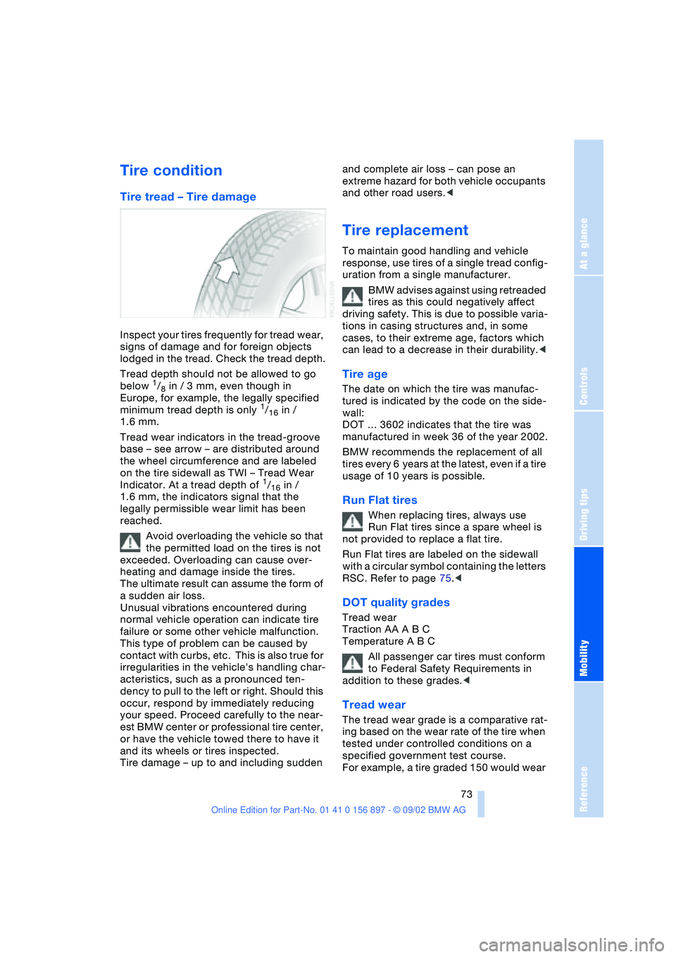
Tread wear indicators in the tread-groove
base – see arrow – are distributed around
the wheel circumference and are labeled
on the tire sidewall as TWI – Tread Wear
Indicator. At a tread depth of
1/16 in /
1.6 mm, the indicators signal that the
legally permissible wear limit has been
reached.
Avoid overloading the vehicle so that
the permitted load on the tires is not
exceeded. Overloading can cause over-
heating and damage inside the tires.
The ultimate result can assume the form of
a sudden air loss.
Unusual vibrations encountered during
normal vehicle operation can indicate tire
failure or some other vehicle malfunction.
This type of problem can be caused by
contact with curbs, etc. This is also true for
irregularities in the vehicle's handling char-
acteristics, such as a pronounced ten-
dency to pull to the left or right. Should this
occur, respond by immediately reducing
your speed. Proceed carefully to the near-
est BMW center or professional tire center,
or have the vehicle towed there to have it
and its wheels or tires inspected.
Tire damage – up to and including sudden and complete air loss – can pose an
extreme hazard for both vehicle occupants
and other road users.<
Tire replacement
To maintain good handling and vehicle
response, use tires of a single tread config-
uration from a single manufacturer.
BMW advises against using retreaded
tires as this could negatively affect
driving safety. This is due to possible varia-
tions in casing structures and, in some
cases, to their extreme age, factors which
can lead to a decrease in their durability.<
Tire age
The date on which the tire was manufac-
tured is indicated by the code on the side-
wall:
DOT … 3602 indicates that the tire was
manufactured in week 36 of the year 2002.
BMW recommends the replacement of all
tires every 6 years at the latest, even if a tire
usage of 10 years is possible.
Run Flat tires
When replacing tires, always use
Run Flat tires since a spare wheel is
not provided to replace a flat tire.
Run Flat tires are labeled on the sidewall
with a circular symbol containing the letters
RSC. Refer to page 75.<
DOT quality grades
Tread wear
Traction AA A B C
Temperature A B C
All passenger car tires must conform
to Federal Safety Requirements in
addition to these grades.<
Tread wear
The tread wear grade is a comparative rat-
ing based on the wear rate of the tire when
tested under controlled conditions on a
specified government test course.
For example, a tire graded 150 would wear
Page 74 of 106
Wheels and tires
74 one and one-half (1 γ) times as well on the
government course as a tire graded 100.
The relative performance of tires depends
upon the actual conditions of their use,
however, and may depart significantly from
the norm due to variations in driving habits,
service practices and differences in road
characteristics and climate.
Traction
The traction grades, from highest to lowest,
are AA, A, B and C.
Those grades represent the tire's ability to
stop on wet pavement as measured under
controlled conditions on specified govern-
ment test surfaces of asphalt and concrete.
A tire marked C may have poor traction
performance.
The traction grade assigned to this
tire is based on straight-ahead brak-
ing traction tests, and does not include
acceleration, cornering, hydroplaning, or
peak traction characteristics.<
Temperature
The temperature grades are A – the
highest – B, and C, representing the tire's
resistance to the generation of heat and its
ability to dissipate heat when tested under
controlled conditions on a specified indoor
laboratory test wheel.
Sustained high temperature can cause the
material of the tire to degenerate and
reduce tire life, and excessive temperature
can lead to sudden tire failure. The grade C
corresponds to a level of performance
which all passenger car tires must meet
under the Federal Motor Vehicle Safety
Standard No. 109. Grades B and A repre-
sent higher levels of performance on the
laboratory test wheel than the minimum
required by law.
The temperature grade for this tire is
established for a tire that is properly
inflated and not overloaded. Excessive
speed, under-inflation, or excessive load-
ing, either separately or in combination,
can cause heat buildup and possible tire
failure.<
Uniform Tire Quality Grading
Quality grades can be found where appli-
cable on the tire sidewall between tread
shoulder and maximum section width. For
example:
Tread wear 200 Traction AA
Temperature A
Wheel and tire combina-
tions
The right choice
Use wheels and tires approved by
BMW for your particular vehicle. Vari-
ations in factors such as manufacturing tol-
erances mean that even wheels and tires
with identical official size ratings could
actually have dimensions different from the
approved units. These differences could
lead to body contact, and with it the risk of
severe accidents. If non-approved wheels
and tires are used, BMW cannot evaluate
their suitability, and therefore cannot be
held liable for driving safety.<
BMW tests certain tire brands for each tire
size, classifies them as road-safe and
approves them. Consult your BMW center
for more information. Observe any country-
specific regulations, e.g. on making a cor-
responding entry in the vehicle documents.
The correct wheel and tire combina-
tion affects different systems such as
ABS, DSC, DTC and DBC. The function of
these systems is impaired if improper
wheel and tire combinations are used.
For this reason, use tires of the same brand
and tread configuration. In the event of a
flat tire, for example, remount the approved
wheel and tire combination as soon as pos-
sible.<
Page 99 of 106

At a glance
Controls
Driving tips
Mobility
Reference
99
Driving lamps
– indicator lamp, defective
bulb 14
Driving notes 65
DSC Dynamic Stability
Control 51
– indicator lamp 14
DTC Dynamic Traction
Control 51
– indicator lamp 14
Dynamic Brake Control
DBC 52
– indicator lamp 14
Dynamic Stability Control
DSC 51
– indicator lamp 14
Dynamic Traction Control
DTC 51
– indicator lamp 14
E
Electric Power Steering
EPS 42
– indicator lamp 15
Electric power windows 22
Electrical convertible
top 25
Electrical fault
– convertible top 25
– door lock 20
– fuel filler door 70
– storage compartment 60
Emergency operation
– convertible top 25
– doors 20
– fuel filler door 70
– storage compartment 60
Emergency release
– from inside luggage
compartment 22
Engine 38
– break-in procedures 64
– starting 38
– switching off 39
Engine compartment 78
Engine coolant 96
– refilling 81Engine oil 79
– capacity 96
– quality 80
– refilling 79
Engine oil consumption 79
Engine oil level 79
– checking 79
Engine oil pressure 79
– indicator lamp 14
Engine oil sensor 79
– indicator lamp 14
Engine oil types 80
Engine output 94
Engine speed 94
EPS Electric Power
Steering 42
ESP, refer to DSC 51
Exhaust system, refer to
High temperatures 65
Exterior mirrors 32
– automatic dimming
feature 33
Eyelet for tow-starting and
towing 90
F
False alarm 28
Fault
– storage compartment 60
First-aid kit 89
Flat tire 73, 75
Flat Tire Monitor 53
– indicator lamp 14, 53
Fog lamps 46
– indicator lamp 14
Footbrake, refer to Driving
notes 65
Front airbags 33
Fuel consumption 50
– display 47
Fuel filler door 70
– unlocking in case of elec-
trical fault 70
Fuel gas cap 70
Fuel gauge 47
Fuel specifications 70, 94
Fuel tank capacity 96
Fuses 88
G
Gasoline gauge, refer to
Fuel gauge 47
Gasoline specifications,
refer to Fuel
specifications 70
Glove compartment 60
Gross vehicle weight,
approved 94
Guide Booklet, Warranty
and Service 82
H
Handbrake 39
Hands-free system 61
Hardtop preparation 67
Hardtop, refer to the sepa-
rate Owner's Manual
Hazard warning flashers 12
Hazard warning triangle 89
Head restraints 30
Headlamp flasher 42, 46
Headlamp washer
system 79, 96
Headlamps 84
– access 84
– high beam 42
Heated seats 31
Heavy loads 66
Height 95
High beams 42, 46
– bulb replacement 85
– indicator lamp 14
High temperatures 65
Hood 77
Hood release 77
Hydraulic brake assistant,
refer to DBC
Hydroplaning 65
I
Ignition lock 38
Imprint 4, 6
Indicator and warning
lamps 14