Page 9 of 92
111
7
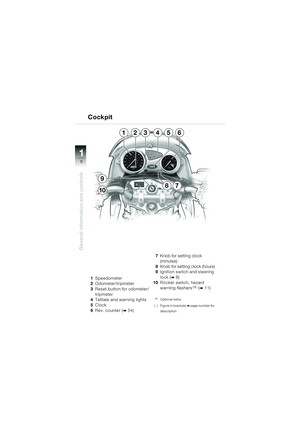
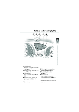
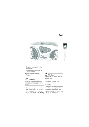
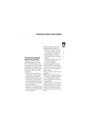
General information and controls1Telltale light,
flashing turn indicators left/
right green
Z
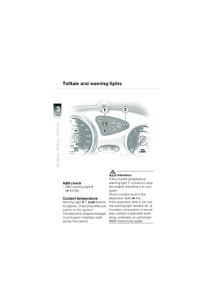
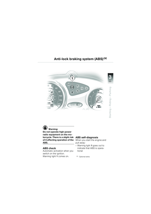
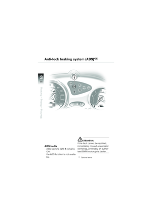
2Warning light, ABS checkOE
red
D (b65)
3 Telltale light,
high-beam headlight blue
q
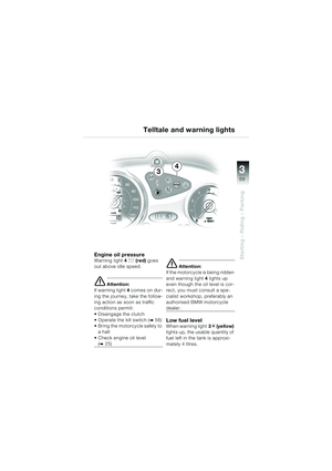
4Warning light, engine oil
pressure red
p (b59)
OEOptional extra
5Warning light, coolant tem-
perature red
j (b58)
6 Telltale light, neutral
green
k
7Warning light,
fuel level when approx.
4 litres left in tank yellow
m
( ) Figure in bracketsbpage number for
description
Telltale and warning lights
13542
76
10K14bkg2.book Seite 7 Montag, 15. September 2003 5:30 17
Page 10 of 92
11
8
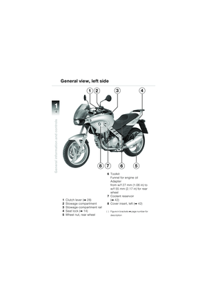
General information and controls
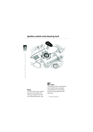
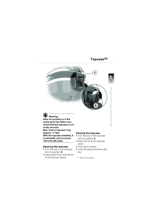
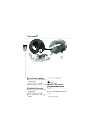
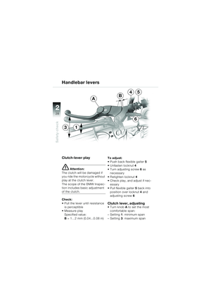
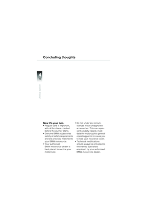
KeysYou will receive two master
keys and one spare key.
The key number is on the
accompanying plastic tag.
L Note:
The ignition switch and steering
lock, fuel filler cap, stowage
compartment
OA and the seat
lock are all operated with the
same key.
OAOptional accessory
Ignition switch and steering lock
10K14bkg2.book Seite 8 Montag, 15. September 2003 5:30 17
Page 11 of 92
111
9
General information and controls
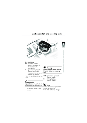
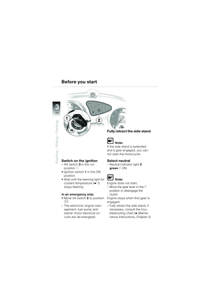
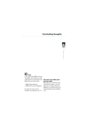
Key positionsONOperating position,
ignition, lights and all
electrical circuits
switched on
R Ignition and lights off,
steering not locked*
(handlebars can be turned
freely to left or right)
Turn the handlebars to full left lock.
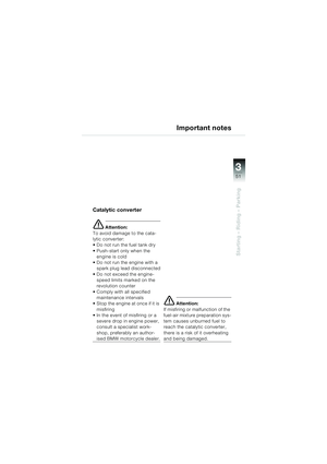
e Attention:
Engage the steering lock with the
handlebars in this position only.
* The key can be removed in these
positions
d Warning:
Never turn the key to OFF or
I while riding the motorcy-
cle!
OFF Ignition and lights off,
steering locked*
IParking light on,
steering locked*
L Note:
Switch the parking light on for
limited periods only.
Note state of battery charge.
Ignition switch and steering lock
10K14bkg2.book Seite 9 Montag, 15. September 2003 5:30 17
Page 12 of 92
11
10
General information and controls
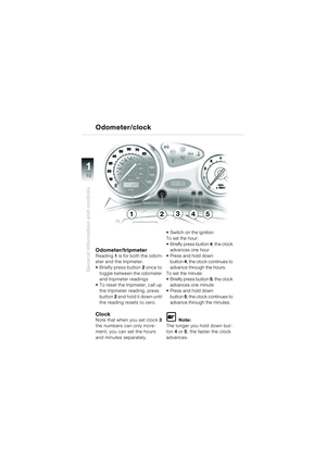
Odometer/tripmeterReading 1 is for both the odom-
eter and the tripmeter.
Briefly press button 2 once to
toggle between the odometer
and tripmeter readings
To reset the tripmeter, call up the tripmeter reading, press
button 2 and hold it down until
the reading resets to zero.
ClockNote that when you set clock 3
the numbers can only incre-
ment; you can set the hours
and minutes separately. Switch on the ignition
To set the hour:
Briefly press button
4; the clock
advances one hour
Press and hold down button 4; the clock continues to
advance through the hours.
To set the minute:
Briefly press button 5; the clock
advances one minute
Press and hold down
button 5; the clock continues to
advance through the minutes.L Note:
The longer you hold down but-
ton 4 or 5, the faster the clock
advances.
Odometer/clock
24513
10K14bkg2.book Seite 10 Montag, 15. September 2003 5:30 17
Page 13 of 92
111
11
General information and controls
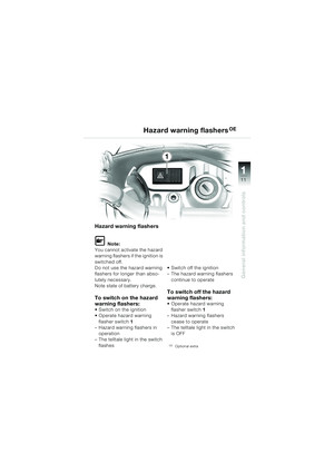
Hazard warning flashers
L Note:
You cannot activate the hazard
warning flashers if the ignition is
switched off.
Do not use the hazard warning
flashers for longer than abso-
lutely necessary.
Note state of battery charge.
To switch on the hazard
warning flashers:
Switch on the ignition
Operate hazard warning flasher switch 1
– Hazard warning flashers in
operation
– The telltale light in the switch
flashes Switch off the ignition
– The hazard warning flashers
continue to operate
To switch off the hazard
warning flashers:
Operate hazard warning flasher switch 1
– Hazard warning flashers
cease to operate
– The telltale light in the switch
is OFF
OEOptional extra
Hazard warning flashersOE
1
10K14bkg2.book Seite 11 Montag, 15. September 2003 5:30 17
Page 14 of 92
11
12
General information and controls
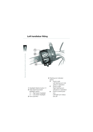
1Headlight-flasher button H
2High-beam/low-beam
headlight switch
FHigh-beam headlight
GLow-beam headlight
3 Horn push
z
4Flashing turn indicator
switch
YPush to left:
Left flashing turn indi-
cators in operation
WPush to right:
Right flashing turn
indicators in operation
▲Push to centre posi-
tion:
Left/right turn indica-
tors off
Left handlebar fitting
1
2
3
4
10K14bkg2.book Seite 12 Montag, 15. September 2003 5:30 17
Page 15 of 92
111
13
General information and controls
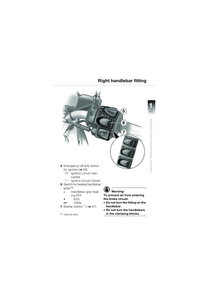
5Emergency off (kill) switch
for ignition (
b56)
VIgnition circuit inter-
rupted
UIgnition circuit closed
6 Switch for heated handlebar
grips
OE
οHandlebar-grip heat-
ing OFF
50%
100%
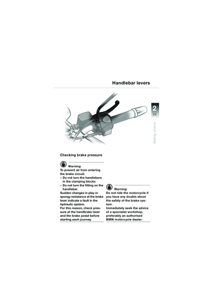
7 Starter button
y (b57)
OEOptional extra
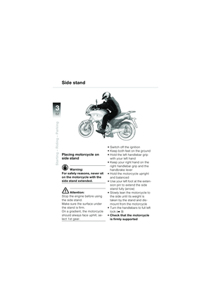
d Warning:
To prevent air from entering
the brake circuit:
Do not turn the fitting on the handlebar.
Do not turn the handlebars
in the clamping blocks.
Right handlebar fitting
5
7
6
10K14bkg2.book Seite 13 Montag, 15. September 2003 5:30 17
Page 16 of 92
11
14
General information and controls
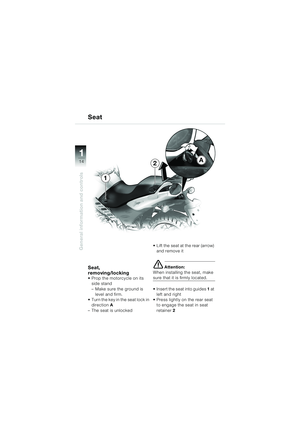
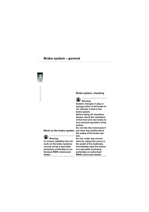
Seat
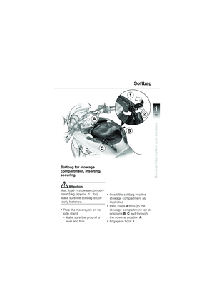
Seat,
removing/locking
Prop the motorcycle on its side stand
– Make sure the ground is level and firm.
Turn the key in the seat lock in direction A
– The seat is unlocked Lift the seat at the rear (arrow)
and remove it
e Attention:
When installing the seat, make
sure that it is firmly located.
Insert the seat into guides 1 at
left and right
Press lightly on the rear seat to engage the seat in seat
retainer 2
A
1
2
10K14bkg2.book Seite 14 Montag, 15. September 2003 5:30 17


 111
7
General information and controls1Telltale light,
flashing turn indicators left/
right green
Z
2Warning light, ABS checkOE
red
D (b65)
3 Telltale light,
high-beam headlight blue
q
4Warni")
 11
8
General information and controls
KeysYou will receive two master
keys and one spare key.
The key number is on the
accompanying plastic tag.
L Note:
The ignition switch and steering
lock, fuel")
 111
9
General information and controls
Key positionsONOperating position,
ignition, lights and all
electrical circuits
switched on
R Ignition and lights off,
steering not locked*
(handlebars can be")
 11
10
General information and controls
Odometer/tripmeterReading 1 is for both the odom-
eter and the tripmeter.
Briefly press button 2 once to
toggle between the odometer
and tripmeter readings")
 111
11
General information and controls
Hazard warning flashers
L Note:
You cannot activate the hazard
warning flashers if the ignition is
switched off.
Do not use the hazard warning
flashers for l")
 11
12
General information and controls
1Headlight-flasher button H
2High-beam/low-beam
headlight switch
FHigh-beam headlight
GLow-beam headlight
3 Horn push
z
4Flashing turn indicator
switch
YPush")
 111
13
General information and controls
5Emergency off (kill) switch
for ignition (
b56)
VIgnition circuit inter-
rupted
UIgnition circuit closed
6 Switch for heated handlebar
grips
OE
οHandlebar-g")
 11
14
General information and controls
Seat
Seat,
removing/locking
Prop the motorcycle on its side stand
– Make sure the ground is level and firm.
Turn the key in the seat lock in direction")