2003 BMW 760LI SEDAN trailer
[x] Cancel search: trailerPage 43 of 229

At a glance
Controls
Driving tips
Communications
Navigation
Entertainment
Mobility
Reference
41
Alarm system
The concept
The vehicle alarm system responds:
>When a door, the hood, or the luggage
compartment lid is opened
>To movement in the vehicle's interior Ð
interior motion sensor
>To changing the vehicle's tilt if someone
attempts to steal the wheels or tow the
vehicle
>To interruption of battery voltage.
The system responds to unauthorized
vehicle entry and attempted theft by simul-
taneously activating:
>An acoustic alarm, which lasts for a
period of approx. 30 seconds
>The hazard warning flashers for approx.
five minutes
>The high beams, which flash on and off
in the same rhythm.
Arming and disarming the alarm
system
When you lock or unlock the vehicle, either
with the remote control unit or at the door
lock, the alarm system is armed or dis-
armed at the same time.
The system indicates that it has been cor-
rectly armed by switching on the hazard
warning flashers for a single cycle and by
emitting an acoustic signal.
You can have different acknowledg-
ment signals set to confirm arming
and disarming.<
You can open the luggage compartment
lid even if the alarm is armed using
button 3of the remote control, refer
to page 36. It is armed once again when
the lid is closed.
Pressing the Panic mode button for a
longer period triggers the alarm, refer
to page 36.<
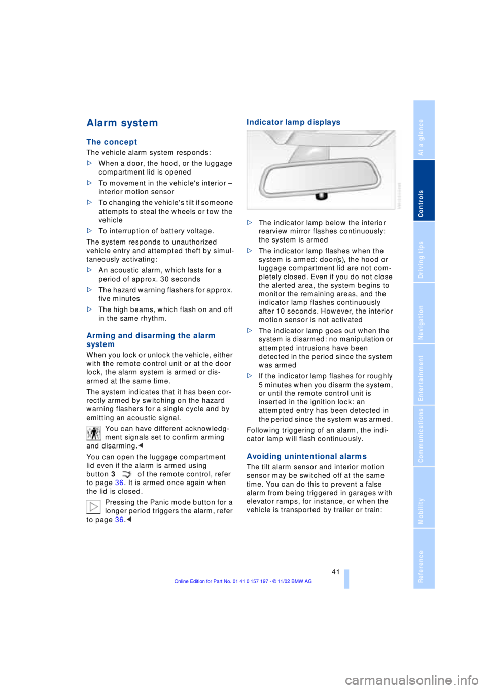
Indicator lamp displays
>The indicator lamp below the interior
rearview mirror flashes continuously:
the system is armed
>The indicator lamp flashes when the
system is armed: door(s), the hood or
luggage compartment lid are not com-
pletely closed. Even if you do not close
the alerted area, the system begins to
monitor the remaining areas, and the
indicator lamp flashes continuously
after 10 seconds. However, the interior
motion sensor is not activated
>The indicator lamp goes out when the
system is disarmed: no manipulation or
attempted intrusions have been
detected in the period since the system
was armed
>If the indicator lamp flashes for roughly
5 minutes when you disarm the system,
or until the remote control unit is
inserted in the ignition lock: an
attempted entry has been detected in
the period since the system was armed.
Following triggering of an alarm, the indi-
cator lamp will flash continuously.
Avoiding unintentional alarms
The tilt alarm sensor and interior motion
sensor may be switched off at the same
time. You can do this to prevent a false
alarm from being triggered in garages with
elevator ramps, for instance, or when the
vehicle is transported by trailer or train:
Page 73 of 229

At a glance
Controls
Driving tips
Communications
Navigation
Entertainment
Mobility
Reference
71
place Ð the transmission lockout is
released.
Re-engage the transmission lockout
after parking the vehicle at its destina-
tion. Otherwise there is a danger that the
vehicle could start to roll if parked on a
steep slope.<
Engaging again
1.Disengage the release lever by pressing
it together with the red detent lever,
arrow 1
2.Guide the release lever all the way back
into its original position Ð the transmis-
sion lockout is again engaged
3.Fold up and lock the cover panel. Now Ð
and not before Ð the key may be
removed.
Once the transmission lockout has
been re-engaged, the warning in the
Check Control should disappear, and the
symbol in the Info Display should change
from N to P. Should this fail to happen,
there is a danger that the vehicle could
start to roll.<
Information on jump-starting, tow-starting
and towing begins on page 202.
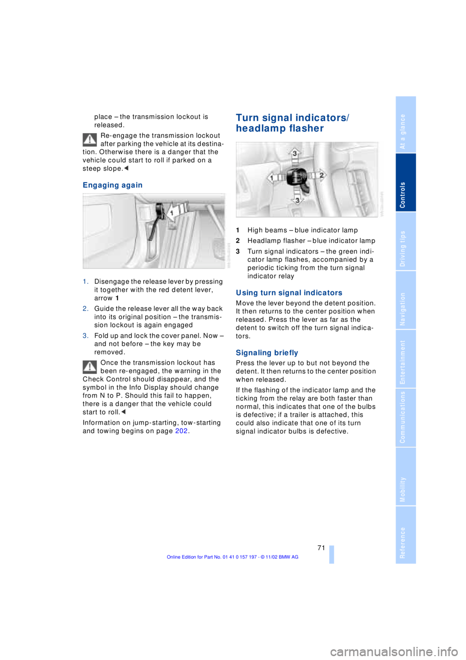
Turn signal indicators/
headlamp flasher
1High beams Ð blue indicator lamp
2Headlamp flasher Ð blue indicator lamp
3Turn signal indicators Ð the green indi-
cator lamp flashes, accompanied by a
periodic ticking from the turn signal
indicator relay
Using turn signal indicators
Move the lever beyond the detent position.
It then returns to the center position when
released. Press the lever as far as the
detent to switch off the turn signal indica-
tors.
Signaling briefly
Press the lever up to but not beyond the
detent. It then returns to the center position
when released.
If the flashing of the indicator lamp and the
ticking from the relay are both faster than
normal, this indicates that one of the bulbs
is defective; if a trailer is attached, this
could also indicate that one of its turn
signal indicator bulbs is defective.
Page 96 of 229

Technology for comfort, convenience and safety
94
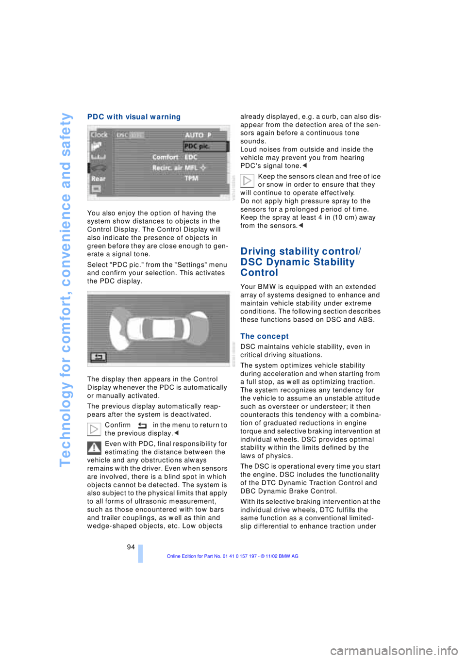
PDC with visual warning
You also enjoy the option of having the
system show distances to objects in the
Control Display. The Control Display will
also indicate the presence of objects in
green before they are close enough to gen-
erate a signal tone.
Select "PDC pic." from the "Settings" menu
and confirm your selection. This activates
the PDC display.
The display then appears in the Control
Display whenever the PDC is automatically
or manually activated.
The previous display automatically reap-
pears after the system is deactivated.
Confirm in the menu to return to
the previous display.<
Even with PDC, final responsibility for
estimating the distance between the
vehicle and any obstructions always
remains with the driver. Even when sensors
are involved, there is a blind spot in which
objects cannot be detected. The system is
also subject to the physical limits that apply
to all forms of ultrasonic measurement,
such as those encountered with tow bars
and trailer couplings, as well as thin and
wedge-shaped objects, etc. Low objects already displayed, e.g. a curb, can also dis-
appear from the detection area of the sen-
sors again before a continuous tone
sounds.
Loud noises from outside and inside the
vehicle may prevent you from hearing
PDC's signal tone.<
Keep the sensors clean and free of ice
or snow in order to ensure that they
will continue to operate effectively.
Do not apply high pressure spray to the
sensors for a prolonged period of time.
Keep the spray at least 4 in (10 cm) away
from the sensors.<
Driving stability control/
DSC Dynamic Stability
Control
Your BMW is equipped with an extended
array of systems designed to enhance and
maintain vehicle stability under extreme
conditions. The following section describes
these functions based on DSC and ABS.
The concept
DSC maintains vehicle stability, even in
critical driving situations.
The system optimizes vehicle stability
during acceleration and when starting from
a full stop, as well as optimizing traction.
The system recognizes any tendency for
the vehicle to assume an unstable attitude
such as oversteer or understeer; it then
counteracts this tendency with a combina-
tion of graduated reductions in engine
torque and selective braking intervention at
individual wheels. DSC provides optimal
stability within the limits defined by the
laws of physics.
The DSC is operational every time you start
the engine. DSC includes the functionality
of the DTC Dynamic Traction Control and
DBC Dynamic Brake Control.
With its selective braking intervention at the
individual drive wheels, DTC fulfills the
same function as a conventional limited-
slip differential to enhance traction under
Page 200 of 229

Replacing components
198 behind a guardrail.
If a warning triangle or portable hazard
warning lamp is required, set it up on the
roadside at an appropriate distance from
the rear of the vehicle. Comply with all
safety guidelines and regulations.
Change the wheel only on a level, firm sur-
face which is not slippery. The vehicle or
the jack could slip to the side if you attempt
to raise the vehicle on a soft or slippery sur-
face such as snow, ice, tiles, etc.
Position the jack on a firm support surface.
Do not use a wooden block or similar
object as a support base for the jack, as
this would prevent it from extending to its
full support height and reduce its load-
carrying capacity.
To avoid serious or fatal injury: never lie
under the vehicle, and never start the
engine while it is supported by the jack.<
What you will need
To avoid rattling noises, note the positions
of the tools before removing them, then
return them to their initial positions after
completing work.
>Lug wrench
Located beside the spare tire >Wheel chock
The chock is located next to the spare
tire, or behind the trim panel on the left
side of the luggage compartment on
vehicles equipped with a trailer cou-
pling.
Remove the floor mat and the cover
above the spare tire.
Unscrew the wingnut and remove the
wheel chock
>Vehicle jack
The jack is located behind the side trim
panel on the right side of the luggage
compartment.
Grasp the handle in the upper panel
and fold it down.
Undo the wingnut and remove the jack.
After use, screw the jack all the way
back down and snap the handle back
into place.
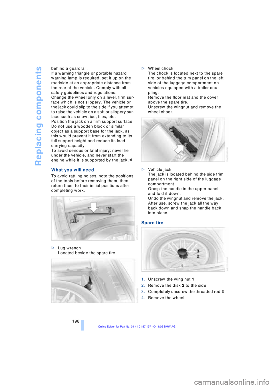
Spare tire
1.Unscrew the wing nut 1
2.Remove the disk 2 to the side
3.Completely unscrew the threaded rod 3
4.Remove the wheel.