Page 145 of 166

145
Run Flat tires*Run Flat tires are labeled on the side-
wall with a circular symbol containing
the letters RSC. Run Flat tires consist of
self-supporting tires and special rims.
The tire reinforcement ensures that the
tire retains some residual safety in the
event of pressure drop and driving
remains possible to a restricted degree.
The vehicle is equipped with a Tire
Pressure Monitor (TPM) or Flat Tire
Monitor, which indicate a flat tire.
Because the sides of Run Flat
tires are reinforced, a drop in infla-
tion pressure usually cannot be
detected from the outside.<
Flat tireIf there is a tire failure, the red warning
lamp symbol lights up. This visual alert
is accompanied by an acoustic warning
signal.
Additional information on the Tire Pres-
sure Monitor (TPM) or Flat Tire Monitor
is found beginning on page 85.
Reduce vehicle speed carefully to
under 50 mph / 80 km/h, avoiding hard
brake applications and steering maneu-
vers.
If the defective wheel is not immedi-
ately recognizable on the outside,
check the tire pressure at all four
wheels.
Have Run Flat tires replaced by
your BMW center. In the interest
of safety, Run Flat tires should not be
repaired. Your BMW center has the
information needed for working with
Run Flat tires and is equipped with the
necessary special tools.<
If appropriate, please consult your
BMW center to reequip your vehi-
cle from summer to winter tires – or vice
versa.<
Driving with a damaged tireRun Flat tires allow you to continue
driving to a restricted degree at a maxi-
mum speed of 50 mph / 80 km/h
depending on the cargo load and the
extent of tire damage. You can deter-
mine the distance you may continue
driving on the basis of the following val-
ues:
>Tire inflation pressure of
0 psi/0 kilopascal (kPa):
approx. 100 miles/150 km
>Tire inflation pressure of approx.
7-15 psi/50-100 kPa:
approx. 300 miles/500 km
>Tire inflation pressure greater than
15 psi/100 kPa:
approx. 600 miles/1,000 km.
Drive cautiously. Do not exceed a
speed of 50 mph / 80 km/h. Be
aware that vehicle handling will be
altered when there is a loss in inflation
pressure. Anticipate, e.g., reduced
tracking during braking, longer braking
distances and changed steering char-
acteristics.<
OverviewControlsMaintenanceRepairsDataIndex
handbook.book Page 145 Saturday, July 27, 2002 1:36 PM
Page 146 of 166

146
BatteryMaintenanceThe battery is absolutely maintenance-
free, that is, the original electrolyte will
normally last for the service life of the
battery under moderate climatic condi-
tions.
Please consult your BMW center
whenever you have any questions
concerning the battery. Since the bat-
tery is absolutely maintenance-free, the
following is for your information only.<
Never disconnect the battery
when the engine is running; the
ensuing voltage surge would seriously
damage the vehicle's onboard elec-
tronic systems.
cle, leave the engine off at all times.
Connect the charge cables to the termi-
nals in the engine compartment. For
terminal locations, refer to Jump-start-
ing on page 147.
Return used batteries to a recy-
cling point or your BMW center.
Maintain the battery in an upright posi-
tion for transport and storage. Secure
the battery against tilting during trans-
port.<
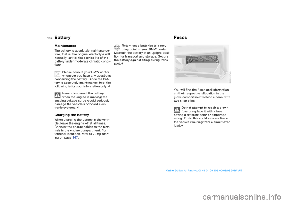
FusesYou will find the fuses and information
on their respective allocation in the
glove compartment behind a panel with
two snap clips.
Do not attempt to repair a blown
fuse or replace it with a fuse
having a different color or amperage
rating. To do this could cause a fire in
the vehicle resulting from a circuit over-
load.<
handbook.book Page 146 Saturday, July 27, 2002 1:36 PM
Page 147 of 166

147 Giving and receiving assistance
Jump-startingWhen your battery is discharged, you
can use two jumper cables to start your
vehicle with power from the battery in a
second vehicle. You can also use the
same method to help start another
vehicle. Only use jumper cables with
fully insulated handles on the terminal
clamps.
Do not touch high-voltage wiring
and cables on a running engine.
Contact with components carrying high
voltage can be harmful or fatal. Care-
fully observe the following instructions
to avoid personal injury and/or damage
to one or both vehicles.<
1. The battery in the support vehicle
must also be rated at 12 volts. This
information is provided on the battery
label
2. Stop the engine of the support vehi-
cle and switch off all electrical com-
ponents in both vehicles – except for
the hazard warning flashers of the
support vehicle
3. Make absolutely certain that there is
no contact between the bodywork of
the two vehicles – short circuit haz-
ard
4. The auxiliary jump-starting terminal
located in your BMW's engine com-
partment acts as the positive battery
terminal. The cover of this auxiliary
terminal is marked with a + sign.
Remove by pulling the tab – see
arrow 1.
Start by connecting the jumper cable
from the positive terminal of the dis-
charged battery to the positive termi-
nal of the support battery
5. Then connect the negative terminals
using the other jumper cable. First
connect one end to the negative bat-
tery terminal or to a suitable ground
on the support vehicle. Then connect
the other end to the negative battery
terminal or to a suitable ground on
the vehicle being started.
Your BMW is equipped with a special
nut for this purpose – see arrow 2
Always adhere to this sequence
when connecting jumper cables;
failure to observe this procedure can
lead to sparks at the battery terminals
and pose an injury hazard.<
6. Start the engine of the support vehi-
cle and let it run for several minutes
at a slightly elevated engine idle
speed
7. Start the engine of the other vehicle
as usual. If the first start attempt is
not successful, wait a few minutes
before another attempt in order to
allow the discharged battery to
recharge
8. Before disconnecting the jumper
cables, let the engines run for a few
minutes
9. Then disconnect the jumper cables
in reverse sequence.
Depending on the cause of the fault,
have the battery recharged by your
BMW center.
OverviewControlsMaintenanceRepairsDataIndex
handbook.book Page 147 Saturday, July 27, 2002 1:36 PM
Page 148 of 166
148
Do not use spray starter fluids to
start the engine.<
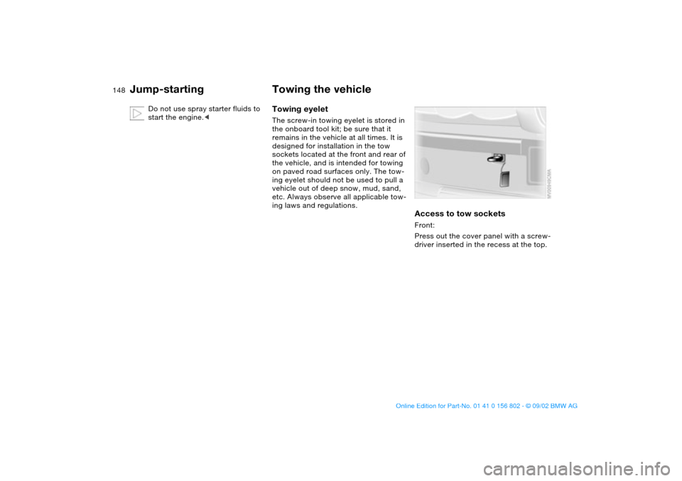
Towing the vehicleTowing eyeletThe screw-in towing eyelet is stored in
the onboard tool kit; be sure that it
remains in the vehicle at all times. It is
designed for installation in the tow
sockets located at the front and rear of
the vehicle, and is intended for towing
on paved road surfaces only. The tow-
ing eyelet should not be used to pull a
vehicle out of deep snow, mud, sand,
etc. Always observe all applicable tow-
ing laws and regulations.
Access to tow socketsFront:
Press out the cover panel with a screw-
driver inserted in the recess at the top.
Jump-starting
handbook.book Page 148 Saturday, July 27, 2002 1:36 PM
Page 149 of 166

149
Rear:
Press out the cover panel with a screw-
driver inserted in the recess at the top.
Make sure the towing eyelet is
firmly screwed all the way in, oth-
erwise the thread could be damaged.
Never attach tie-down hooks, chains,
straps, or tow hooks to tie rods, control
arms, or any other part of the vehicle
suspension, as severe damage to these
components will occur, possibly lead-
ing to accidents.<
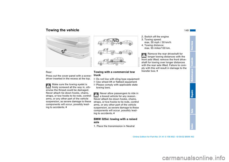
Towing with a commercial tow
truck>Do not tow with sling-type equipment
>Use wheel-lift or flatbed equipment
>Please comply with applicable state
towing laws.
Never allow passengers to ride in
a towed vehicle for any reason.
Never attach tie-down hooks, chains,
straps, or tow hooks to tie rods, control
arms, or any other part of the vehicle
suspension, as severe damage to these
components will occur, possibly lead-
ing to accidents.
axle1. Place the transmission in Neutral
2. Switch off the engine
3. Towing speed:
max. 30 mph / 50 km/h
4. Towing distance:
max. 95 miles/150 km.
Remove the rear driveshaft for
longer towing distances with the
front axle lifted; remove the front drive-
shaft for towing over longer distances
with the rear axle lifted. Failure to com-
ply with this will result in damage to the
transfer box.<
Towing the vehicle
OverviewControlsMaintenanceRepairsDataIndex
handbook.book Page 149 Saturday, July 27, 2002 1:36 PM
Page 150 of 166
150handbook.book Page 150 Saturday, July 27, 2002 1:36 PM
Page 151 of 166
151
Overview
Controls and features
Operation, maintenance
Owner service procedures
Technical data
Index
OverviewControlsMaintenanceRepairsDataIndex
handbook.book Page 151 Saturday, July 27, 2002 1:36 PM
Page 152 of 166
152
Engine data
BMW 325i, 325xi
Displacement
Number of cylinderscu in/cm
3
152.2/2,494
6
Maximum power output
at engine speedhp/kW
rpm184/135
6,000
Maximum torque
at engine speedlb ft/Nm
rpm175/237
3,500
Compression ratioε10.5
Stroke
Borein/mm
in/mm2.95/75
3.31/84
Fuel-injection system Digital electronic engine-management system (DME)
BMW 325xi: power can be tested only on a suitable dynamometer.
handbook.book Page 152 Saturday, July 27, 2002 1:36 PM