Page 86 of 96

Downloaded from www.Manualslib.com manuals search engine 86
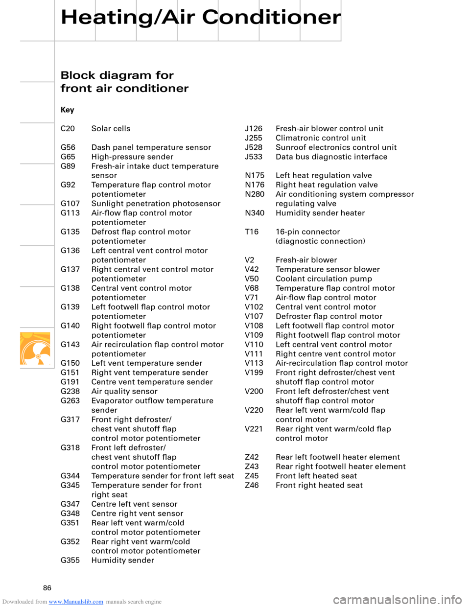
J126 Fresh-air blower control unit
J255 Climatronic control unit
J528 Sunroof electronics control unit
J533 Data bus diagnostic interface
N175 Left heat regulation valve
N176 Right heat regulation valve
N280 Air conditioning system compressor
regulating valve
N340 Humidity sender heater
T16 16-pin connector
(diagnostic connection)
V2 Fresh-air blower
V42 Temperature sensor blower
V50 Coolant circulation pump
V68 Temperature flap control motor
V71 Air-flow flap control motor
V102 Central vent control motor
V107 Defroster flap control motor
V108 Left footwell flap control motor
V109 Right footwell flap control motor
V110 Left central vent control motor
V111 Right centre vent control motor
V113 Air-recirculation flap control motor
V199 Front right defroster/chest vent
shutoff flap control motor
V200 Front left defroster/chest vent
shutoff flap control motor
V220 Rear left vent warm/cold flap
control motor
V221 Rear right vent warm/cold flap
control motor
Z42 Rear left footwell heater element
Z43 Rear right footwell heater element
Z45 Front left heated seat
Z46 Front right heated seat
Block diagram for
front air conditioner
Key
C20 Solar cells
G56 Dash panel temperature sensor
G65 High-pressure sender
G89 Fresh-air intake duct temperature
sensor
G92 Temperature flap control motor
potentiometer
G107 Sunlight penetration photosensor
G113 Air-flow flap control motor
potentiometer
G135 Defrost flap control motor
potentiometer
G136 Left central vent control motor
potentiometer
G137 Right central vent control motor
potentiometer
G138 Central vent control motor
potentiometer
G139 Left footwell flap control motor
potentiometer
G140 Right footwell flap control motor
potentiometer
G143 Air recirculation flap control motor
potentiometer
G150 Left vent temperature sender
G151 Right vent temperature sender
G191 Centre vent temperature sender
G238 Air quality sensor
G263 Evaporator outflow temperature
sender
G317 Front right defroster/
chest vent shutoff flap
control motor potentiometer
G318 Front left defroster/
chest vent shutoff flap
control motor potentiometer
G344 Temperature sender for front left seat
G345 Temperature sender for front
right seat
G347 Centre left vent sensor
G348 Centre right vent sensor
G351 Rear left vent warm/cold
control motor potentiometer
G352 Rear right vent warm/cold
control motor potentiometer
G355 Humidity sender
Heating/Air Conditioner
Page 87 of 96
Downloaded from www.Manualslib.com manuals search engine M
MMMMMMMMMMMMM
M
V50 N175 N176G238 G65 G107 G348 G347Z43 Z42
J126
V2Z45 G344 Z46
G345 3015
SS
15A5A
75
S
25A
75
S
25A
C20
S
20A
N340G355
J528J533
S
10A
30
G89
G150 G151 G263
V221
V111 V110 V220
V102 V68 V109 V108 V199 V200 V107 V71 V113J255 V42 G5658S
58S
G143G113 G135
G318G317G139
G140G92
G138G351G136
G137G35231
inout
2
31
4
G191
N280
M
T16
Colour code
= Input signal
= Output signal
= Positive supply
= Earth
= Convenience CAN High
= Convenience CAN Low
= LIN busAdditional signals
Climate control LIN bus for
– Heated windscreen
control unit J505
– Driver seat ventilation
control unit J672
– Front passenger seat ventilation
control unit J673
1Terminal 30/blower
Terminal 30/front seat heating
Input/rear roller blind switch E1492
3
4
SSP282_109
Page 89 of 96

Downloaded from www.Manualslib.com manuals search engine 89
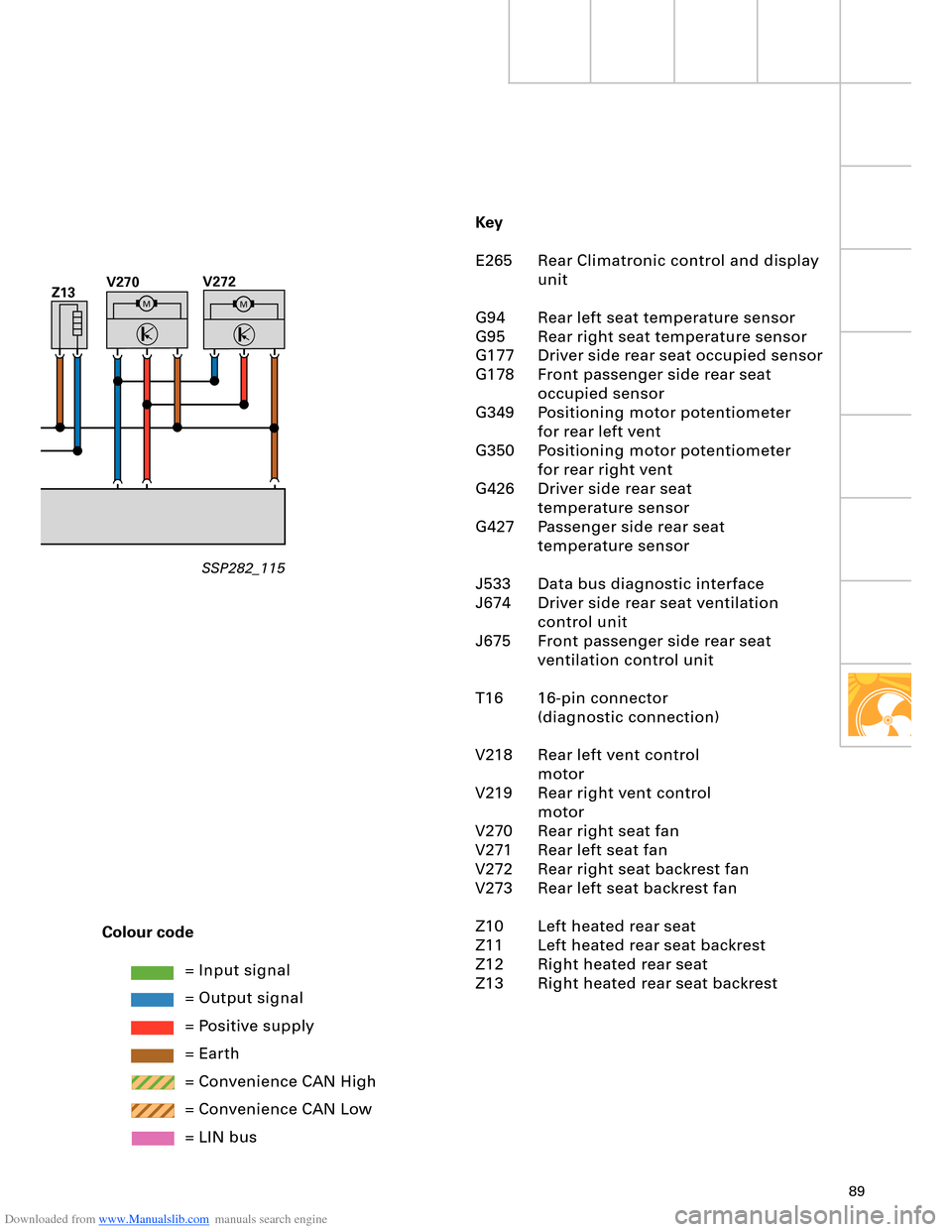
Key
E265 Rear Climatronic control and display
unit
G94 Rear left seat temperature sensor
G95 Rear right seat temperature sensor
G177 Driver side rear seat occupied sensor
G178 Front passenger side rear seat
occupied sensor
G349 Positioning motor potentiometer
for rear left vent
G350 Positioning motor potentiometer
for rear right vent
G426 Driver side rear seat
temperature sensor
G427 Passenger side rear seat
temperature sensor
J533 Data bus diagnostic interface
J674 Driver side rear seat ventilation
control unit
J675 Front passenger side rear seat
ventilation control unit
T16 16-pin connector
(diagnostic connection)
V218 Rear left vent control
motor
V219 Rear right vent control
motor
V270 Rear right seat fan
V271 Rear left seat fan
V272 Rear right seat backrest fan
V273 Rear left seat backrest fan
Z10 Left heated rear seat
Z11 Left heated rear seat backrest
Z12 Right heated rear seat
Z13 Right heated rear seat backrest Colour code
= Input signal
= Output signal
= Positive supply
= Earth
= Convenience CAN High
= Convenience CAN Low
= LIN bus
Z13V272MM
V270
SSP282_115
Page 90 of 96

Downloaded from www.Manualslib.com manuals search engine 90
Auxiliary heater/coolant additional heater
An auxiliary heater is available as an option
for all vehicle and engine versions. The
auxiliary heater with petrol engines and
additional heater with diesel engines are
integrated into the engine coolant circuit.
Vehicles with diesel engine are fitted with an
additional heater as standard. On diesel
engines with auxiliary heater, the activated
auxiliary heater is also used as engine
additional heater depending on temperature.
Heating/Air Conditioner
Design and operation are described in
SSP 240 – Audi A2 Technical Features.
Operation with cut-in by way of remote
control or timer
In the Audi A8 ´03, the auxiliary heater is
activated by the air conditioner. The heated
coolant is initially supplied to the passenger
compartment (primarily auxiliary heater
mode). On attaining pre-determined
temperature levels, engine pre-heating is
then switched in in line with a characteristic
curve.
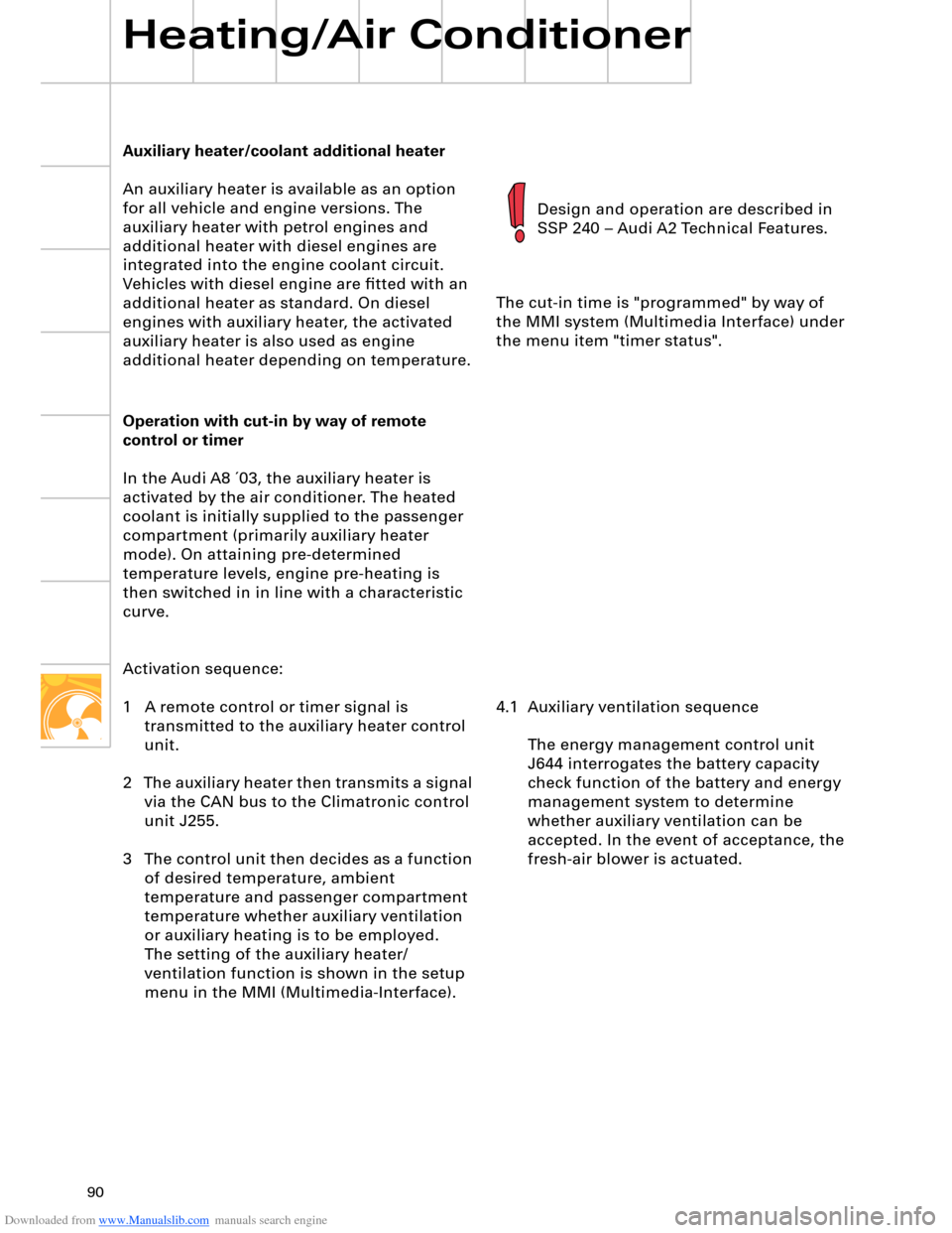
Activation sequence:
1 A remote control or timer signal is
transmitted to the auxiliary heater control
unit.
2 The auxiliary heater then transmits a signal
via the CAN bus to the Climatronic control
unit J255.
3 The control unit then decides as a function
of desired temperature, ambient
temperature and passenger compartment
temperature whether auxiliary ventilation
or auxiliary heating is to be employed.
The setting of the auxiliary heater/
ventilation function is shown in the setup
menu in the MMI (Multimedia-Interface).The cut-in time is "programmed" by way of
the MMI system (Multimedia Interface) under
the menu item "timer status".
4.1 Auxiliary ventilation sequence
The energy management control unit
J644 interrogates the battery capacity
check function of the battery and energy
management system to determine
whether auxiliary ventilation can be
accepted. In the event of acceptance, the
fresh-air blower is actuated.
Page:
< prev 1-8 9-16 17-24