2003 AUDI A8 bus
[x] Cancel search: busPage 60 of 96
Downloaded from www.Manualslib.com manuals search engine 60
LOCAL INTERCONNECT NETWORK
Electrical System
The familiar CAN bus (two-wire bus) is
supplemented by the following bus systems:
– LIN bus (single-wire data bus)
– MOST bus (optical data bus)
– Bluetooth
TM (wireless data bus)
LIN bus
LIN stands for Local Interconnect Network.
Local Interconnect means that all control
units are located within a limited structural
space (e.g. roof). This is also referred to as
"local sub-system".
Data are exchanged between the individual
LIN bus systems in a vehicle by one control
unit in each case using the CAN data bus.
The LIN bus system is a single-wire data bus.
The wire has a basic colour (violet) and a code
colour.
The wire cross-section is 0.35 mm
2. A screen is
not necessary.
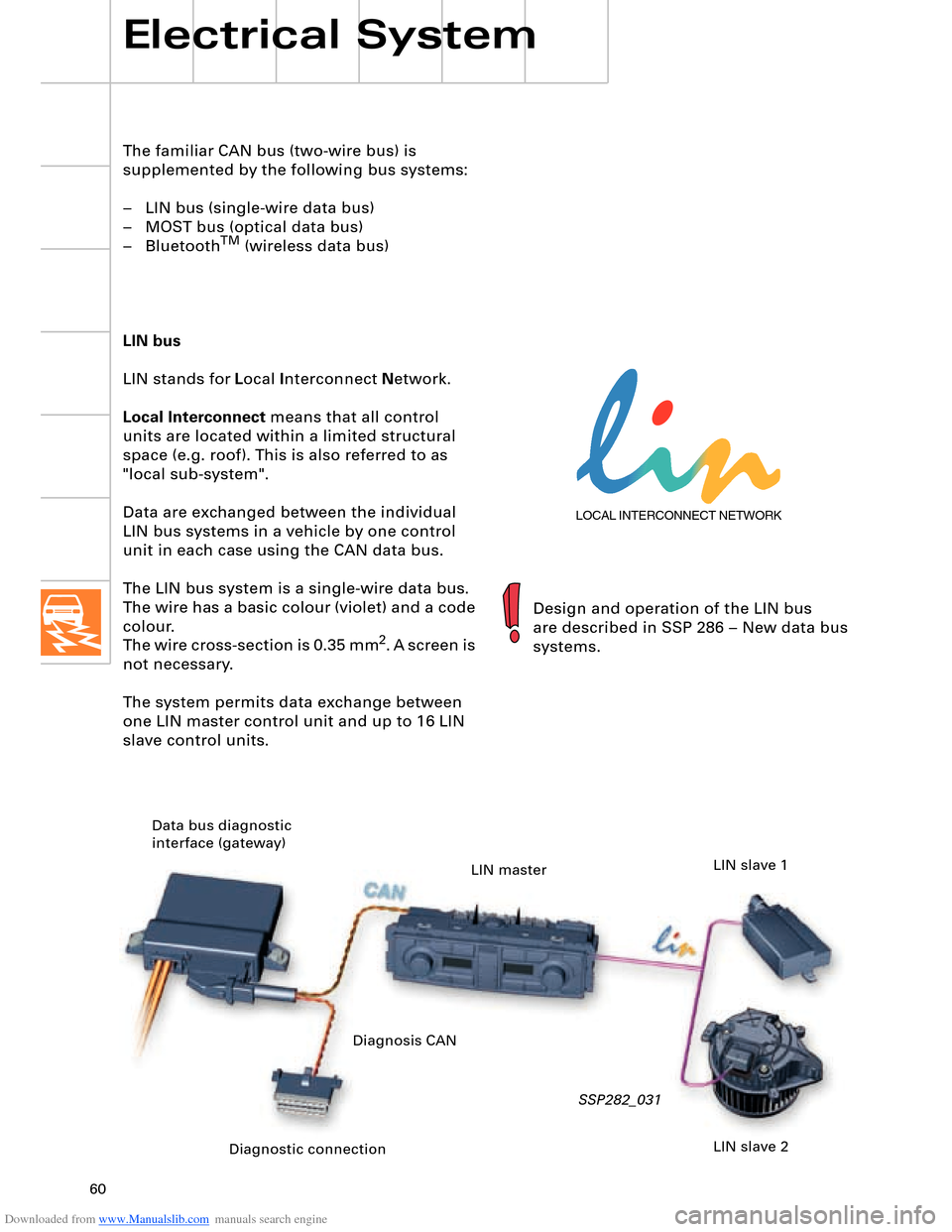
The system permits data exchange between
one LIN master control unit and up to 16 LIN
slave control units.
SSP282_031
Design and operation of the LIN bus
are described in SSP 286 – New data bus
systems.
Diagnostic connection Data bus diagnostic
interface (gateway)
LIN master
LIN slave 2 LIN slave 1
Diagnosis CAN
Page 61 of 96
Downloaded from www.Manualslib.com manuals search engine 61
Media Oriented Systems Transport
R
The name of this data bus system is derived
from "Media Oriented Systems Transport
(MOST) Cooperation". This is an association
formed by various motor vehicle
manufacturers, their suppliers and software
companies with a view to developing
a standard high-speed data transfer system. MOST bus
The term "Media Oriented Systems Transport"
signifies a network featuring media-oriented
data transport. This means that, in contrast to
the CAN data bus, address-oriented
messages are transmitted to a specific
receiver.
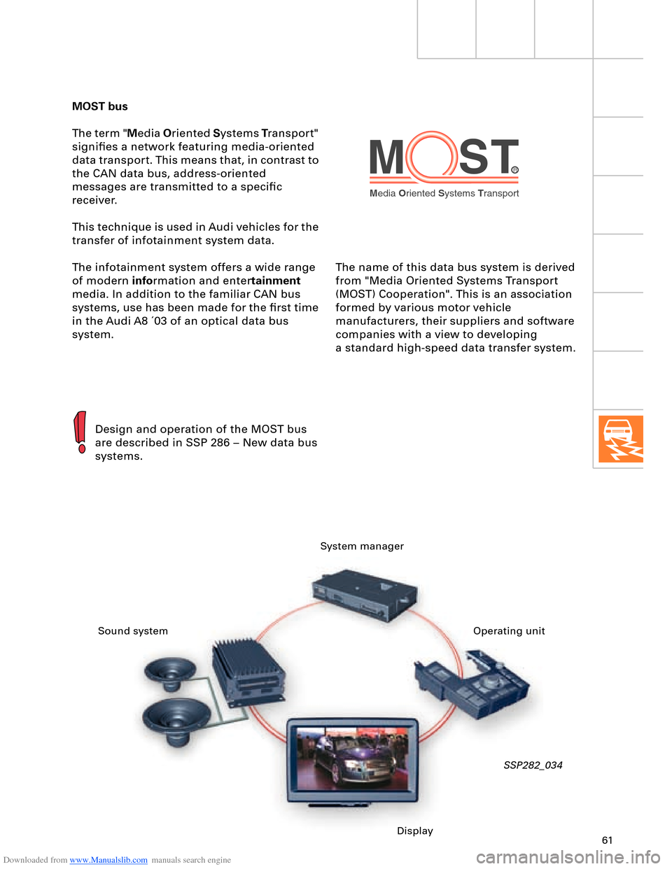
This technique is used in Audi vehicles for the
transfer of infotainment system data.
The infotainment system offers a wide range
of modern information and entertainment
media. In addition to the familiar CAN bus
systems, use has been made for the first time
in the Audi A8 ´03 of an optical data bus
system.
SSP282_034
Design and operation of the MOST bus
are described in SSP 286 – New data bus
systems.
System manager
Sound system
DisplayOperating unit
Page 62 of 96
Downloaded from www.Manualslib.com manuals search engine 62
Electrical System
BluetoothTM
BluetoothTM is an internationally standardised
remote control data interface.
It permits control or monitoring of even
minute units using radio waves.
The primary aim when developing this new
type of interface was to create a wireless
alternative to cable links, which used to be
susceptible to interference and inconvenient
and frequently featured incompatible
connectors.
More and more manufacturers are making use
of "Bluetooth
TM" radio wave technology for
example for wireless interconnection of
notebook and mobile phone accessories.
As initiator and main contributor to the
development of this new transmission
technology, the Swedish company Ericsson
chose the name "Bluetooth".
The name originates from the Viking king
Harald Blåtand II (Danish, literally meaning
"Blue Tooth"), who lived around 1000 years ago
in Denmark and Norway.
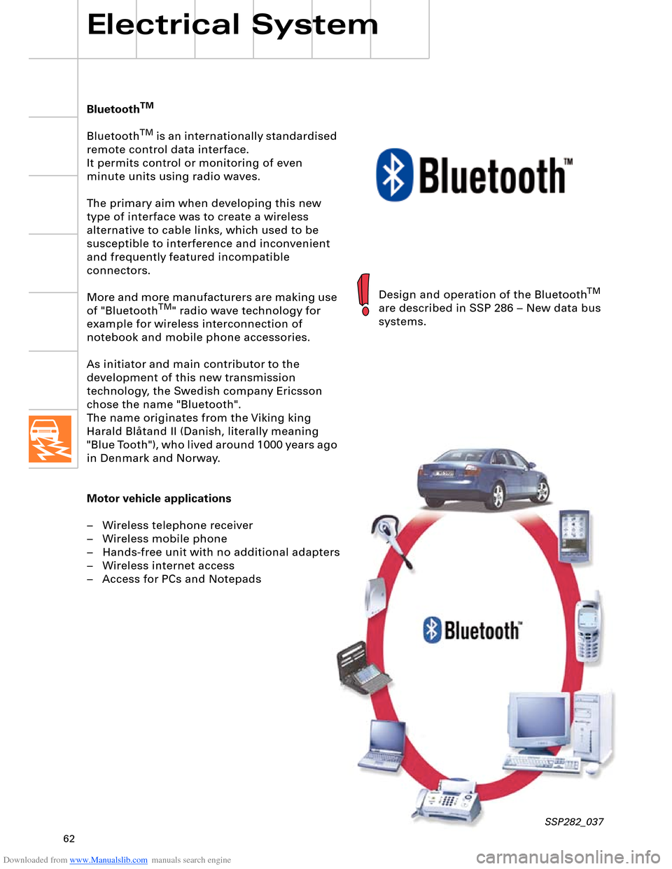
Motor vehicle applications
– Wireless telephone receiver
– Wireless mobile phone
– Hands-free unit with no additional adapters
– Wireless internet access
– Access for PCs and Notepads
SSP282_037
Design and operation of the BluetoothTM
are described in SSP 286 – New data bus
systems.
Page 63 of 96
Downloaded from www.Manualslib.com manuals search engine 63
Vehicle electrical system
A major factor in terms of vehicle reliability is
one which is never even seen: the electrical
system.
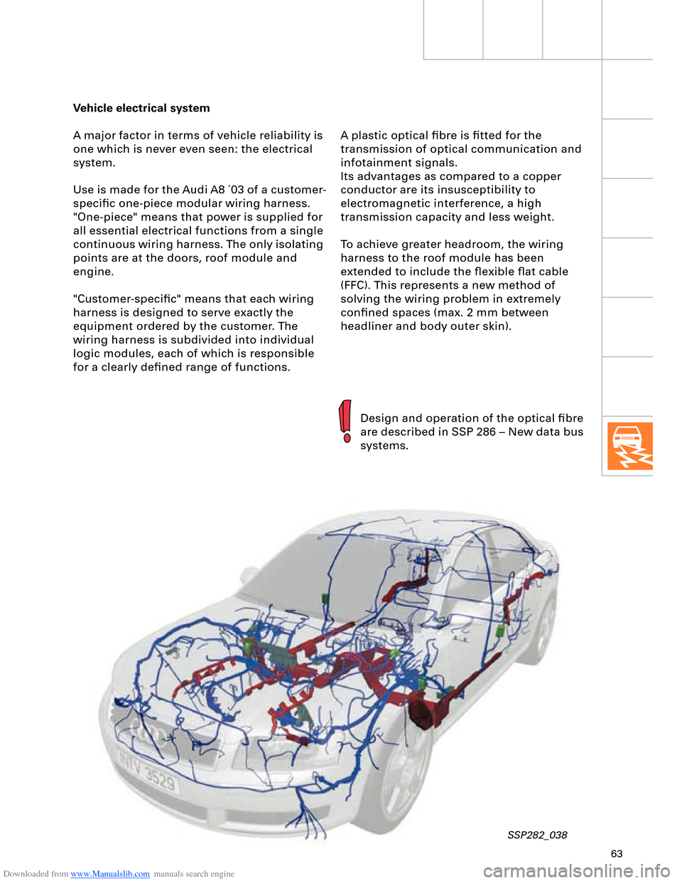
Use is made for the Audi A8 ´03 of a customer-
specific one-piece modular wiring harness.
"One-piece" means that power is supplied for
all essential electrical functions from a single
continuous wiring harness. The only isolating
points are at the doors, roof module and
engine.
"Customer-specific" means that each wiring
harness is designed to serve exactly the
equipment ordered by the customer. The
wiring harness is subdivided into individual
logic modules, each of which is responsible
for a clearly defined range of functions.
SSP282_038
Design and operation of the optical fibre
are described in SSP 286 – New data bus
systems. A plastic optical fibre is fitted for the
transmission of optical communication and
infotainment signals.
Its advantages as compared to a copper
conductor are its insusceptibility to
electromagnetic interference, a high
transmission capacity and less weight.
To achieve greater headroom, the wiring
harness to the roof module has been
extended to include the flexible flat cable
(FFC). This represents a new method of
solving the wiring problem in extremely
confined spaces (max. 2 mm between
headliner and body outer skin).
Page 66 of 96
Downloaded from www.Manualslib.com manuals search engine 66
Electrical System
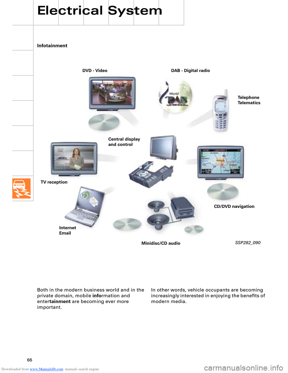
Both in the modern business world and in the
private domain, mobile information and
entertainment are becoming ever more
important. In other words, vehicle occupants are becoming
increasingly interested in enjoying the benefits of
modern media.
SSP282_090
Infotainment
DVD - Video
TV reception
Minidisc/CD audio Internet
EmailTelephone
Telematics DAB - Digital radio
CD/DVD navigation Central display
and control
Page 73 of 96
Downloaded from www.Manualslib.com manuals search engine 7374
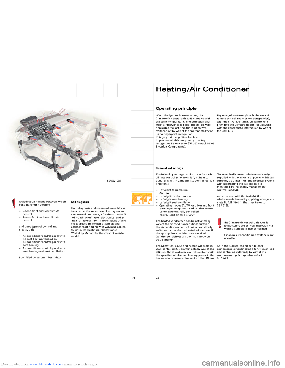
A distinction is made between two air
conditioner unit versions
– 2-zone front and rear climate
control
– 4-zone front and rear climate
control
and three types of control and
display unit
– Air conditioner control panel with
no seat heating/ventilation
– Air conditioner control panel with
seat heating
– Air conditioner control panel with
seat heating and seat ventilation
(identified by part number index).
SSP282_099
Self-diagnosis
Fault diagnosis and measured value blocks
for air conditioner and seat heating system
can be read out by way of address words 08
"Air conditioner/heater electronics" and 28
"Rear climate control". The functions of and
exact procedure for self-diagnosis and
assisted fault-finding with VAS 5051 can be
found in the Heating/Air Conditioner
Workshop Manual for the relevant vehicle
model.
Operating principle
When the ignition is switched on, the
Climatronic control unit J255 starts up with
the same temperature, air distribution and
fresh-air blower speed settings etc. as were
applicable the last time the ignition was
switched off by way of the appropriate key or
using fingerprint recognition.
If fingerprint recognition has been
implemented, this has priority over key
recognition (refer also to SSP 287 – Audi A8 ´03
Electrical Components).
Personalised settings
The following settings can be made for each
climate control zone (front left, right and,
optionally, with 4-zone climate control rear left
and right):
– Left/right temperature
– Air flow
– Left/right air distribution
– Left/right seat heating
– Left/right seat ventilation
– Operating modes (AUTO for driver and front
passenger, temperature-adjustable centre
vents, automatically controlled
recirculated-air mode, ECON)
The heated windscreen can be activated by
way of the air conditioner defrost button or
the air conditioner control unit automatically
switches on the electric heated windscreen if
the appropriate conditions are satisfied
(windscreen defrost or automatic mode on
cold starting).
The Climatronic J255 and heated windscreen
J505 control units communicate by way of the
LIN bus. The Climatronic control unit transmits
the specified windscreen heating power to the
heated windscreen control unit on the LIN bus.
Heating/Air Conditioner
Key recognition takes place in the case of
remote control (radio or key transponder),
with the driver identification control unit
providing the Climatronic control unit J255
with the appropriate information by way of
the CAN bus.
The electrically heated windscreen is only
supplied with the amount of power which can
currently be drawn from the electrical system
without draining the battery. This is
monitored by the energy management
control unit J644.
As is the case with the Audi A4, the
windscreen is heated by applying voltage to a
metallic foil fitted in the glass (refer to
SSP 213).
As in the Audi A4, the air conditioner
compressor is regulated as a function of load
and controlled externally by way of the
compressor regulating valve (refer to
SSP 240). The Climatronic control unit J255 is
connected to the convenience CAN, via
which diagnosis is also performed.
A manual air conditioning system is not
available.
Page 80 of 96
Downloaded from www.Manualslib.com manuals search engine 80
Heating/Air Conditioner
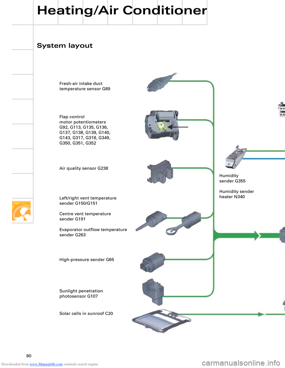
SSP282_103 Fresh-air intake duct
temperature sensor G89
Flap control
motor potentiometers
G92, G113, G135, G136,
G137, G138, G139, G140,
G143, G317, G318, G349,
G350, G351, G352
Air quality sensor G238
Left/right vent temperature
sender G150/G151
Centre vent temperature
sender G191
Evaporator outflow temperature
sender G263
High-pressure sender G65
Sunlight penetration
photosensor G107
Solar cells in sunroof C20
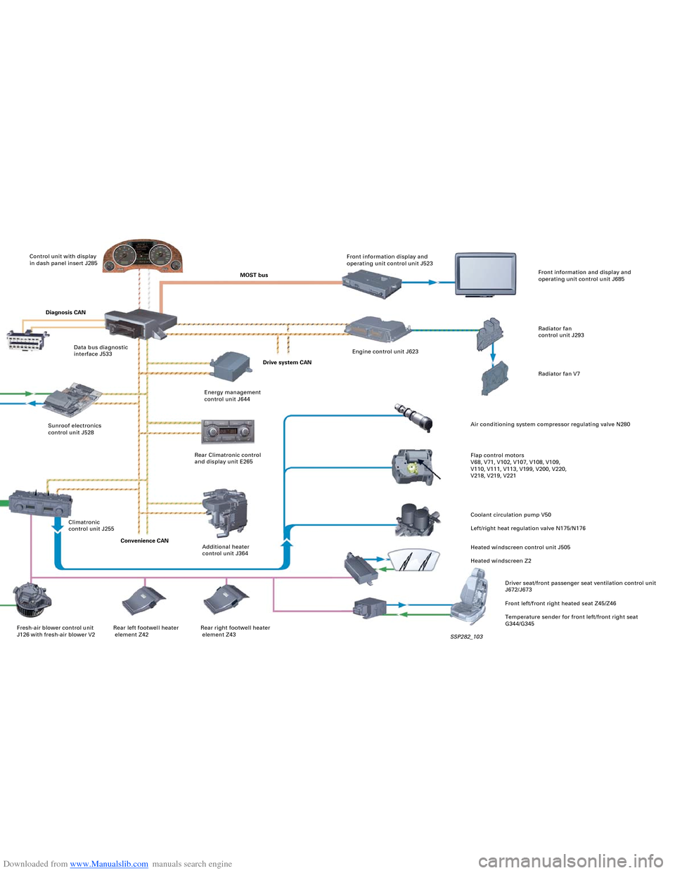
System layoutControl unit with display
in dash panel insert J285
MOST busFront information display and
operating unit control unit J523
Rear right footwell heater
element Z43 Rear left footwell heater
element Z42 Fresh-air blower control unit
J126 with fresh-air blower V2Diagnosis CAN
Data bus diagnostic
interface J533
Sunroof electronics
control unit J528 Humidity
sender G355
Humidity sender
heater N340
Climatronic
control unit J255
Convenience CAN
Additional heater
control unit J364 Rear Climatronic control
and display unit E265Energy management
control unit J644Drive system CANEngine control unit J623Front information and display and
operating unit control unit J685
Radiator fan
control unit J293
Radiator fan V7
Air conditioning system compressor regulating valve N280
Flap control motors
V68, V71, V102, V107, V108, V109,
V110, V111, V113, V199, V200, V220,
V218, V219, V221
Coolant circulation pump V50
Left/right heat regulation valve N175/N176
Heated windscreen control unit J505
Heated windscreen Z2
Driver seat/front passenger seat ventilation control unit
J672/J673
Front left/front right heated seat Z45/Z46
Temperature sender for front left/front right seat
G344/G345
Page 81 of 96
Downloaded from www.Manualslib.com manuals search engine 80
Heating/Air Conditioner
SSP282_103 Fresh-air intake duct
temperature sensor G89
Flap control
motor potentiometers
G92, G113, G135, G136,
G137, G138, G139, G140,
G143, G317, G318, G349,
G350, G351, G352
Air quality sensor G238
Left/right vent temperature
sender G150/G151
Centre vent temperature
sender G191
Evaporator outflow temperature
sender G263
High-pressure sender G65
Sunlight penetration
photosensor G107
Solar cells in sunroof C20
System layoutControl unit with display
in dash panel insert J285
MOST busFront information display and
operating unit control unit J523
Rear right footwell heater
element Z43 Rear left footwell heater
element Z42 Fresh-air blower control unit
J126 with fresh-air blower V2Diagnosis CAN
Data bus diagnostic
interface J533
Sunroof electronics
control unit J528 Humidity
sender G355
Humidity sender
heater N340
Climatronic
control unit J255
Convenience CAN
Additional heater
control unit J364 Rear Climatronic control
and display unit E265Energy management
control unit J644Drive system CANEngine control unit J623Front information and display and
operating unit control unit J685
Radiator fan
control unit J293
Radiator fan V7
Air conditioning system compressor regulating valve N280
Flap control motors
V68, V71, V102, V107, V108, V109,
V110, V111, V113, V199, V200, V220,
V218, V219, V221
Coolant circulation pump V50
Left/right heat regulation valve N175/N176
Heated windscreen control unit J505
Heated windscreen Z2
Driver seat/front passenger seat ventilation control unit
J672/J673
Front left/front right heated seat Z45/Z46
Temperature sender for front left/front right seat
G344/G345