Page 256 of 694
3 - 44
INSP
ADJ
STEERING HEAD INSPECTION AND ADJUSTMENT
2. Inspect:
�Bearing free play
Exist play → Replace.
STEERING HEAD INSPECTION AND
ADJUSTMENT
1. Elevate the front wheel by placing a suit-
able stand under the engine.
2. Check:
�Steering stem
Grasp the bottom of the forks and gen-
tly rock the fork assembly back and
forth.
Free play → Adjust steering head.
3. Check:
�Steering smooth action
Turn the handlebar lock to lock.
Unsmooth action → Adjust steering ring
nut.
4. Adjust:
�Steering ring nut
Steering ring nut adjustment steps:
�Remove the headlight.
�Remove the handlebar and upper bracket.
�Loosen the steering ring nut 1 using the
steering nut wrench 2.
Steering nut wrench:
YU-33975/90890-01403
Page 262 of 694
3 - 47
INSP
ADJ
ELECTRICAL/SPARK PLUG INSPECTION
EC370000
ELECTRICAL
EC371001
SPARK PLUG INSPECTION
1. Remove:
�Spark plug
2. Inspect:
�Electrode 1
Wear/damage → Replace.
�Insulator color 2
Normal condition is a medium to light
tan color.
Distinctly different color → Check the
engine condition.
NOTE:
When the engine runs for many hours at low
speeds, the spark plug insulator will become
sooty, even if the engine and carburetor are in
good operating condition.
3. Measure:
�Plug gap a
Use a wire gauge or thickness gauge.
Out of specification → Regap.
4. Clean the plug with a spark plug cleaner
if necessary.
Spark plug gap:
0.7 ~ 0.8 mm (0.028 ~ 0.031 in)
5. Tighten:
�Spark plug
NOTE:
�Before installing a spark plug, clean the gas-
ket surface and plug surface.
�Finger-tighten a the spark plug before
torquing to specification b.
T R..13 Nm (1.3 m · kg, 9.4 ft · lb)
Page 264 of 694
3 - 48
INSP
ADJ
IGNITION TIMING CHECK
IGNITION TIMING CHECK
1. Remove:
�Timing mark accessing screw 1
2. Attach:
�Timing light
�Inductive tachometer
To the spark plug lead.
3. Check:
�Ignition timing
Timing light:
YM-33277-A/90890-03141
Inductive tachometer:
YU-8036-B
Engine tachometer:
90890-03113
Checking steps:
�Start the engine and let it warm up. Let the
engine run at the specified speed.
Engine speed:
1,800 ~ 2,100 r/min
�Visually check the stationary pointer a is
within the firing range b on the rotor.
Incorrect firing range → Check rotor and
pickup assembly.
4. Install:
�Timing mark accessing screw
Page 450 of 694

4 - 91
ENGCRANKCASE AND CRANKSHAFT
REMOVAL POINTS
Crankcase
1. Separate:
�Right crankcase
�Left crankcase
Separation steps:
�Remove the crankcase bolts 1, hose
guide 2 and clutch cable holder 3.
NOTE:
Loosen each bolt 1/4 of a turn at a time and
after all the bolts are loosened, remove
them.
�Remove the right crankcase 4.
NOTE:
�Place the crankcase with its left side
downward and split it by inserting a screw-
driver tip into the splitting slit a in the
crankcase.
�Lift the right crankcase horizontally while
lightly patting the case splitting slit and
engine mounting boss using a soft ham-
mer, and leave the crankshaft and trans-
mission with the left crankcase.
CAUTION:
Use soft hammer to tap on the case half.
Tap only on reinforced portions of case.
Do not tap on gasket mating surface.
Work slowly and carefully. Make sure the
case halves separate evenly. If one end
“hangs up”, take pressure off the push
screw, realign, and start over. If the
cases do not separate, check for a
remaining case screw or fitting. Do not
force.
�Remove the dowel pins and O-ring.
a
4
Page 460 of 694
4 - 96
ENGCRANKCASE AND CRANKSHAFT
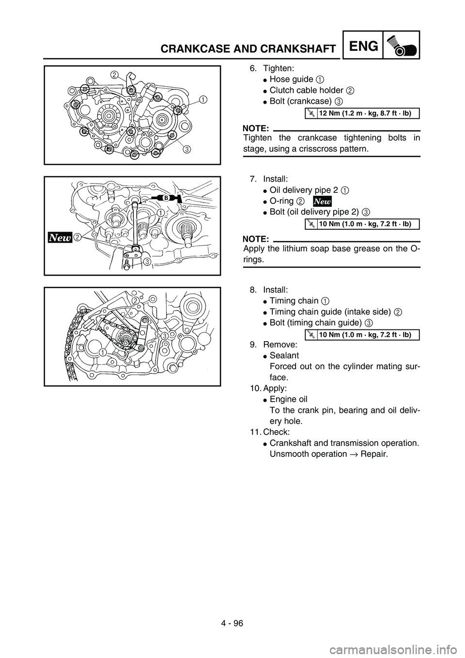
6. Tighten:
�Hose guide 1
�Clutch cable holder 2
�Bolt (crankcase) 3
NOTE:
Tighten the crankcase tightening bolts in
stage, using a crisscross pattern.
T R..12 Nm (1.2 m · kg, 8.7 ft · lb)
7. Install:
�Oil delivery pipe 2 1
�O-ring 2
�Bolt (oil delivery pipe 2) 3
NOTE:
Apply the lithium soap base grease on the O-
rings.
T R..10 Nm (1.0 m · kg, 7.2 ft · lb)
8. Install:
�Timing chain 1
�Timing chain guide (intake side) 2
�Bolt (timing chain guide) 3
9. Remove:
�Sealant
Forced out on the cylinder mating sur-
face.
10. Apply:
�Engine oil
To the crank pin, bearing and oil deliv-
ery hole.
11. Check:
�Crankshaft and transmission operation.
Unsmooth operation → Repair.
T R..10 Nm (1.0 m · kg, 7.2 ft · lb)
Page 470 of 694
4 - 101
ENGTRANSMISSION, SHIFT CAM AND SHIFT FORK
5. Install:
�Shift fork 1 (L) 1
�Shift fork 2 (C) 2
�Shift fork 3 (R) 3
�Shift cam 4
To main axle and drive axle.
NOTE:
�Apply the molybdenum disulfide oil on the
shift fork grooves.
�Mesh the shift fork #1 (L) with the 4th wheel
gear 5 and #3 (R) with the 5th wheel gear
7 on the drive axle.
�Mesh the shift fork #2 (C) with the 3rd pinion
gear 6 on the main axle.
6. Install:
�Transmission assembly 1
To left crankcase 2.
NOTE:
Apply the engine oil on the bearings and guide
bars.
7. Check:
�Shifter operation
�Transmission operation
Unsmooth operation → Repair.
Page 612 of 694
–+ELEC
6 - 3
IGNITION SYSTEM
EC620000
IGNITION SYSTEM
INSPECTION STEPS
Use the following steps for checking the possibility of the malfunctioning engine being attributable to
ignition system failure and for checking the spark plug which will not spark.
*marked: Only when the ignition checker is used.
NOTE:
�
Remove the following parts before inspection.
1) Seat
2) Fuel tank
�
Use the following special tools in this inspection.
Dynamic spark tester:
YM-34487
Ignition checker:
90890-06754
Pocket tester:
YU-3112-C/90890-03112
Spark gap test*Clean or replace
spark plug.
Check entire ignition
system for connection.Repair or replace.
Check engine stop switch. Replace.
Check ignition coil. Primary coil Replace.
Secondary coil Replace.
Check CDI magneto. Pickup coil Replace.
Charging coil Replace.
Check neutral switch. Repair or replace.
Replace CDI unit.
No spark
OK
OK
OK
OK
OK
Spark
No good
No good
No good
No good
No good
No good
No good
Page 616 of 694
6 - 4
–+ELEC
IGNITION SYSTEM
SPARK GAP TEST
1. Disconnect the spark plug cap from spark
plug.
2. Connect the dynamic spark tester
1
(ignition checker
2
) as shown.
�
Spark plug cap
3
�
Spark plug
4
Å
For USA and CDN
ı
Except for USA and CDN
3. Kick the kickstarter crank.
4. Check the ignition spark gap.
5. Start engine, and increase spark gap until
misfire occurs. (for USA and CDN only)
Minimum spark gap:
6.0 mm (0.24 in)
Å
ı
EC624000
COUPLERS AND LEADS CONNECTION
INSPECTION
1. Check:
�
Couplers and leads connection
Rust/dust/looseness/short-circuit
→
Repair or replace.
ENGINE STOP SWITCH INSPECTION
1. Inspect:
�
Engine stop switch conduct
No continuous while being pushed
→
Replace.
Continuous while being freed
→
Replace.
Tester (+) lead
→
Black/White lead
1
Tester (–) lead
→
Black lead
2
B/W
1
B
2
Tester selec-
tor position
PUSH IN
Ω
×
1
FREE