Page 81 of 694
SPEC
2 - 6
MAINTENANCE SPECIFICATIONS
Stem runout limit ---- 0.01 mm
(0.0004 in)
Valve seat width IN 0.9 ~ 1.1 mm
(0.0354 ~ 0.0433 in)1.6 mm
(0.0630 in)
EX 0.9 ~ 1.1 mm
(0.0354 ~ 0.0433 in)1.6 mm
(0.0630 in)
Valve spring:
Free length IN 37.81 mm (1.49 in) 35.9 mm
(1.41 in)
EX 37.54 mm (1.48 in) 35.7 mm
(1.41 in)
Set length (valve closed) IN 29.13 mm (1.15 in) ----
EX 29.30 mm (1.15 in) ----
Compressed pressure
(installed) IN 99 ~ 114 N
(10.1 ~ 11.6 kg, 22.27 ~ 25.57 lb)----
EX 126 ~ 144 N
(12.9 ~ 14.7 kg, 28.44 ~ 32.41 lb)----
Tilt limit IN ---- 2.5˚/ 1.7 mm
(2.5˚/0.067 in)
EX ---- 2.5˚/1.6 mm
(2.5˚/0.063 in)
Direction of winding
(top view) IN Clockwise ----
EX Clockwise ----
Piston:
Piston to cylinder clearance 0.040 ~ 0.065 mm
(0.0016 ~ 0.0026 in)0.1 mm
(0.004 in)
Piston size “D”76.955 ~ 76.970 mm
(3.0297 ~ 3.0303 in)----
Measuring point “H”8 mm (0.31 in) ----
Piston off-set 0.5 mm (0.020 in)/IN-side ----Item Standard Limit
*
H
D
Page 176 of 694

3 - 5
INSP
ADJ
EC350000
ENGINE
EC351011
COOLANT LEVEL INSPECTION
WARNING
Do not remove the radiator cap 1, drain
bolt and hoses when the engine and radia-
tor are hot. Scalding hot fluid and steam
may be blown out under pressure, which
could cause serious injury.
When the engine has cooled, place a thick
towel over the radiator cap, slowly rotate
the cap counterclockwise to the detent.
This procedure allows any residual pres-
sure to escape. When the hissing sound
has stopped, press down on the cap while
turning counterclockwise and remove it.
CAUTION:
Hard water or salt water is harmful to the
engine parts. You may use distilled water, if
you can’t get soft water.
1. Place the machine on a level place, and
hold it in an upright position.
2. Inspect:
�Coolant level
Coolant level should be between the
maximum a and minimum b marks.
Coolant level is below the “LOW” level
line → Add soft water (tap water) up to
the proper level.
3. Start the engine and let it warm up for
several minutes.
4. Turn off the engine and check the coolant
level again.
NOTE:
Before checking the coolant level, wait a few
minutes until the coolant settles.
LOWFULLCOOLANT
a
b
COOLANT REPLACEMENT
WARNING
Do not remove the radiator cap when the
engine is hot.
ENGINE/COOLANT LEVEL INSPECTION/
COOLANT REPLACEMENT
Page 188 of 694
3 - 11
INSP
ADJTHROTTLE LUBRICATION/
DECOMPRESSION ADJUSTMENT
THROTTLE LUBRICATION
1. Remove:
�Cover (throttle cable cap) 1
�Cover (grip cap) 2
�Throttle grip cap 3
2. Apply:
�Lithium soap base grease
On the throttle cable end a.
3. Install:
�Throttle grip cap
�Screw (throttle grip cap)
�Cover (grip cap)
�Cover (throttle cable cap)
T R..4 Nm (0.4 m · kg, 2.9 ft · lb)
DECOMPRESSION ADJUSTMENT
1. Check:
�Decompression lever free play a
Out of specification → Adjust.
Checking steps:
�Remove the timing mark accessing screw
1 and crankshaft end accessing screw
2.
�Turn the crankshaft counterclockwise with
a wrench.
NOTE:
Squeezing the decompression lever allows
the crankshaft to be turned easily.
�Align the T.D.C. mark b on the rotor with
the align mark c on the crankcase cover
when piston is at T.D.C. on compression
stroke.
�Check the free play.
Free play a:
5 ~ 9 mm (0.20 ~ 0.35 in)
Page 208 of 694
3 - 21
INSP
ADJ
VALVE CLEARANCE INSPECTION AND ADJUSTMENT
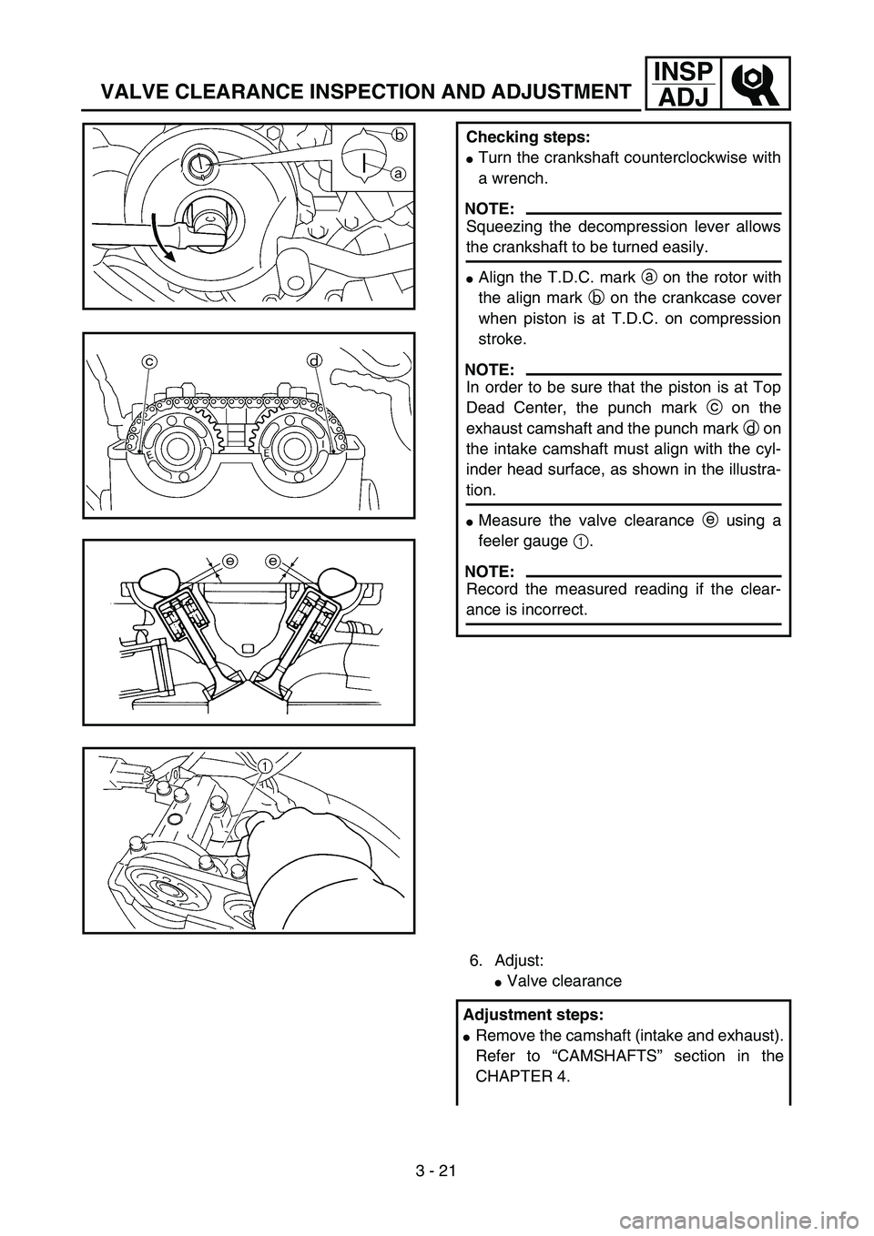
Checking steps:
�Turn the crankshaft counterclockwise with
a wrench.
NOTE:
Squeezing the decompression lever allows
the crankshaft to be turned easily.
�Align the T.D.C. mark a on the rotor with
the align mark b on the crankcase cover
when piston is at T.D.C. on compression
stroke.
NOTE:
In order to be sure that the piston is at Top
Dead Center, the punch mark c on the
exhaust camshaft and the punch mark d on
the intake camshaft must align with the cyl-
inder head surface, as shown in the illustra-
tion.
�Measure the valve clearance e using a
feeler gauge 1.
NOTE:
Record the measured reading if the clear-
ance is incorrect.
6. Adjust:
�Valve clearance
Adjustment steps:
�Remove the camshaft (intake and exhaust).
Refer to “CAMSHAFTS” section in the
CHAPTER 4.
Page 238 of 694

3 - 35
INSP
ADJ
DRIVE CHAIN SLACK ADJUSTMENT
EC36A060
DRIVE CHAIN SLACK ADJUSTMENT
1. Elevate the rear wheel by placing the
suitable stand under the engine.
2. Check:
�Drive chain slack a
Above the seal guard installation bolt.
Out of specification → Adjust.
NOTE:
Before checking and/or adjusting, rotate the
rear wheel through several revolutions and
check the slack several times to find the tight-
est point. Check and/or adjust the drive chain
slack with the rear wheel in this “tight chain”
position.
Drive chain slack:
40 ~ 50 mm (1.6 ~ 2.0 in)
3. Adjust:
�Drive chain slack
Drive chain slack adjustment steps:
�Loosen the axle nut 1 and locknuts 2.
�Adjust the drive chain slack by turning the
adjusters 3.
To tighten → Turn the adjuster 3 coun-
terclockwise.
To loosen → Turn the adjuster 3 clock-
wise and push wheel forward.
�Turn each adjuster exactly the same
amount to maintain correct axle alignment.
(There are marks a on each side of the
drive chain puller alignment.)
NOTE:
Turn the adjuster so that the drive chain is in
line with the sprocket, as viewed from the rear.
CAUTION:
Too small drive chain slack will overload
the engine and other vital parts; keep the
slack within the specified limits.
�Tighten the axle nut while pushing down
the drive chain.
T R..
Axle nut:
125 Nm (12.5 m • kg, 90 ft • lb)
�Tighten the locknuts.
Page 278 of 694

4 - 5
ENG
RADIATOR
EC456000
HANDLING NOTE
WARNING
Do not remove the radiator cap when the
engine and radiator are hot. Scalding hot
fluid and steam may be blown out under
pressure, which could cause serious
injury.
When the engine has cooled, open the radi-
ator cap by the following procedure:
Place a thick rag, like a towel, over the radi-
ator cap, slowly rotate the cap counter-
clockwise to the detent. This procedure
allows any residual pressure to escape.
When the hissing sound has stopped,
press down on the cap while turning coun-
terclockwise and remove it.
EC454000
INSPECTION
EC444100
Radiator
1. Inspect:
�
Radiator core
1
Obstruction
→
Blow out with com-
pressed air through rear of the radiator.
Bent fin
→
Repair/replace.
EC455000
ASSEMBLY AND INSTALLATION
Radiator
1. Install:
�
O-ring
1
�
Radiator pipe
2
�
Bolt (radiator pipe)
3
NOTE:
Apply the lithium soap base grease on the O-
ring.
2. Install:
�
Radiator hose 4 (longer)
1
�
Radiator hose 2 (shorter)
2
To right radiator 3.
T R..10 Nm (1.0 m · kg, 7.2 ft · lb)
Page 314 of 694

4 - 23
ENGCAMSHAFTS
REMOVAL POINTS
Camshaft
1. Remove:
�Timing mark accessing screw 1
�Crankshaft end accessing screw 2
2. Align:
�T.D.C. mark
With align mark.
Checking steps:
�Turn the crankshaft counterclockwise with
a wrench.
NOTE:
Squeezing the decompression lever allows
the crankshaft to be turned easily.
�Align the T.D.C. mark a on the rotor with
the align mark b on the crankcase cover
when piston is at T.D.C. on compression
stroke.
NOTE:
In order to be sure that the piston is at Top
Dead Center, the punch mark c on the
exhaust camshaft and the punch mark d on
the intake camshaft must align with the cyl-
inder head surface, as shown in the illustra-
tion.
3. Remove:
�Timing chain tensioner cap bolt 1
�Timing chain tensioner 2
�Gasket
4. Remove:
�Bolt (camshaft cap) 1
�Camshaft cap 2
�Clip
NOTE:
Remove the bolts (camshaft cap) in a criss-
cross pattern, working from the outside in.
CAUTION:
The bolts (camshaft cap) must be removed
evenly to prevent damage to the cylinder
head, camshafts or camshaft caps.
Page 320 of 694

4 - 26
ENGCAMSHAFTS
Timing chain tensioner
1. Check:
�While pressing the tensioner rod lightly
with fingers, use a thin screwdriver 1
and wind the tensioner rod up fully
clockwise.
�When releasing the screwdriver by
pressing lightly with fingers, make sure
that the tensioner rod will come out
smoothly.
�If not, replace the tensioner assembly.
ASSEMBLY AND INSTALLATION
Camshaft
1. Install:
�Exhaust camshaft 1
�Intake camshaft 2
Installation steps:
�Turn the crankshaft counterclockwise with
a wrench.
NOTE:
Squeezing the decompression lever allows
the crankshaft to be turned easily.
�Align the T.D.C. mark a on the rotor with
the align mark b on the crankcase cover
when piston is at T.D.C. on compression
stroke.
�Fit the timing chain 3 onto both camshaft
sprockets and install the camshafts on the
cylinder head.
NOTE:
The camshafts should be installed onto the
cylinder head so that the punch mark c on
the exhaust camshaft and the punch mark
d on the intake camshaft must align with
the cylinder head surface, as shown in the
illustration.

Valve seat width IN 0.9 ~ 1.1 mm
(0.0354 ~ 0.0433 in)1.6 mm
(0.0630 in)
EX 0.9 ~ 1.1 mm
(0.0354 ~ 0.0433 in)1.6")