Page 480 of 694

1
�
Spacer
2
�
Bearing (right)
3
�
Oil seal
4
NOTE:")
5 - 5
CHAS
FRONT WHEEL AND REAR WHEEL
EC595000
ASSEMBLY AND INSTALLATION
Front wheel
1. Install:
�
Bearing (left)
1
�
Spacer
2
�
Bearing (right)
3
�
Oil seal
4
NOTE:
�
Apply the lithium soap base grease on the
bearing and oil seal lip when installing.
�
Use a socket that matches the outside diam-
eter of the race of the bearing.
�
Left side of bearing shall be installed first.
�
Install the oil seal with its manufacture’s
marks or numbers facing outward.
CAUTION:
Do not strike the inner race of the bearing.
Contact should be made only with the outer
race.
2. Install:
�Brake disc 1
�Bolt (brake disc) 2
NOTE:
Tighten the bolts in stage, using a crisscross
pattern.
T R..12 Nm (1.2 m · kg, 8.7 ft · lb)
3. Install:
�Collar 1
NOTE:
�Apply the lithium soap base grease on the oil
seal lip.
�Install the collar with their projection a fac-
ing the wheel.
4. Install:
�Trip meter gear unit 1
NOTE:
Make sure the two projections a in the wheel
hub are meshed with the two slots b in the trip
meter gear unit.b a1
Page 486 of 694
5 - 8
CHAS
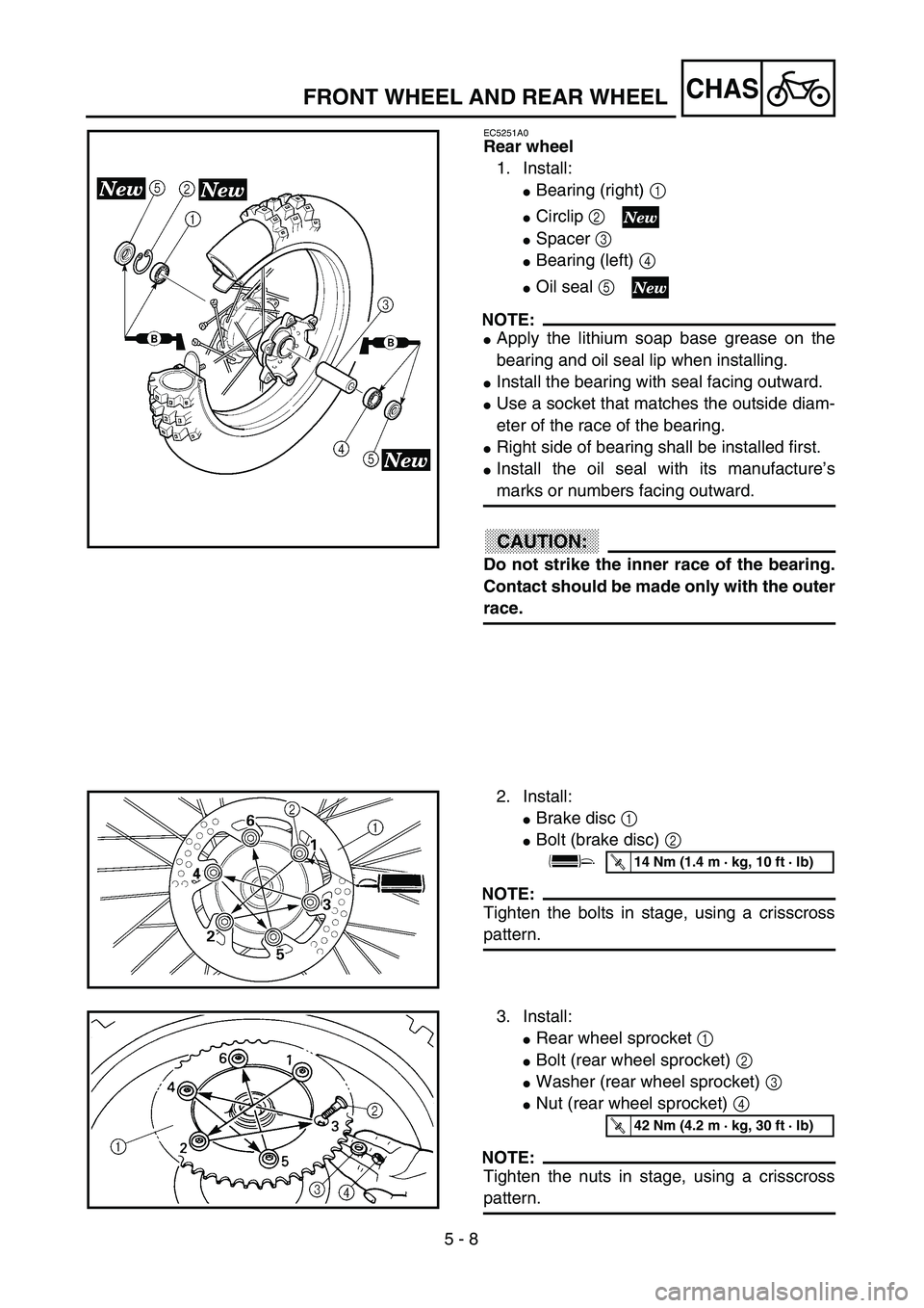
EC5251A0
Rear wheel
1. Install:
�Bearing (right) 1
�Circlip 2
�Spacer 3
�Bearing (left) 4
�Oil seal 5
NOTE:
�Apply the lithium soap base grease on the
bearing and oil seal lip when installing.
�Install the bearing with seal facing outward.
�Use a socket that matches the outside diam-
eter of the race of the bearing.
�Right side of bearing shall be installed first.
�Install the oil seal with its manufacture’s
marks or numbers facing outward.
CAUTION:
Do not strike the inner race of the bearing.
Contact should be made only with the outer
race.
2. Install:
�Brake disc 1
�Bolt (brake disc) 2
NOTE:
Tighten the bolts in stage, using a crisscross
pattern.
T R..14 Nm (1.4 m · kg, 10 ft · lb)
3. Install:
�Rear wheel sprocket 1
�Bolt (rear wheel sprocket) 2
�Washer (rear wheel sprocket) 3
�Nut (rear wheel sprocket) 4
NOTE:
Tighten the nuts in stage, using a crisscross
pattern.
T R..42 Nm (4.2 m · kg, 30 ft · lb)
FRONT WHEEL AND REAR WHEEL
Page 488 of 694
5 - 9
CHASFRONT WHEEL AND REAR WHEEL
4. Install:
�Collar 1
NOTE:
Apply the lithium soap base grease on the oil
seal lip.
5. Install:
�Wheel
NOTE:
Install the brake disc 1 between the brake
pads 2 correctly.
6. Install:
�Drive chain 1
NOTE:
Push the wheel 2 forward and install the drive
chain.
7. Install:
�Left drive chain puller 1
�Wheel axle 2
NOTE:
�Install the left drive chain puller, and insert
the wheel axle from left side.
�Apply the lithium soap base grease on the
wheel axle.
8. Install:
�Right drive chain puller 1
�Washer 2
�Nut (wheel axle) 3
NOTE:
Temporarily tighten the nut (wheel axle) at this
point.
Page 522 of 694
5 - 26
CHASFRONT BRAKE AND REAR BRAKE
2. Install:
�Brake hose holder 1
�Screw (brake hose holder) 2
CAUTION:
After installing the brake hose holders,
make sure the brake hose does not contact
the spring (rear shock absorber). If it does,
correct its twist.
Brake fluid
1. Fill:
�Brake fluid
Until the fluid level reaches “LOWER”
level line a.
WARNING
�Use only the designated quality brake
fluid:
otherwise, the rubber seals may deterio-
rate, causing leakage and poor brake per-
formance.
�Refill with the same type of brake fluid;
mixing fluids may result in a harmful chem-
ical reaction and lead to poor performance.
�Be careful that water does not enter the
master cylinder when refilling. Water will
significantly lower the boiling point of the
fluid and may result in vapor lock.
CAUTION:
Brake fluid may erode painted surfaces or
plastic parts. Always clean up spilled fluid
immediately.
ÅFront
ıRear
Recommended brake fluid:
DOT #4
T R..1 Nm (0.1 m · kg, 0.7 ft · lb)
Å
ı
Page 528 of 694
5 - 29
CHASFRONT FORK
EC558000
FRONT FORK DISASSEMBLY
Extent of removal:1 Oil seal removal2 Damper rod removal
Extent of removal Order Part name Q’ty Remarks
FRONT FORK DISASSEMBLY
1 Front fork cap bolt 1 Refer to “REMOVAL POINTS”.
2 Fork spring 1 Drain the fork oil.
3 Dust seal 1
Refer to “REMOVAL POINTS”. 4 Stopper ring 1
5 Inner tube 1
6 Outer tube 1
7 Piston metal 1
8 Slide metal 1
9 Oil seal washer 1
0 Oil seal 1
A Spring guide 1
B Base valve 1 Use special tool.
C Damper rod 1 Refer to “REMOVAL POINTS”.
1
2
Page 530 of 694

5 - 30
CHASFRONT FORK
EC556000
HANDLING NOTE
NOTE:
The front fork requires careful attention. So it is
recommended that the front fork be main-
tained at the dealers.
CAUTION:
To prevent an accidental explosion of air,
the following instructions should be
observed:
�The front fork with a built-in piston rod
has a very sophisticated internal con-
struction and is particularly sensitive to
foreign material.
Use enough care not to allow any foreign
material to come in when the oil is
replaced or when the front fork is disas-
sembled and reassembled.
�Before removing the cap bolts or front
forks, be sure to extract the air from the
air chamber completely.
EC553000
REMOVAL POINTS
Front fork cap bolt
1. Remove:
�Front fork cap bolt 1
From the outer tube.
NOTE:
Before removing the front fork from the
machine, loosen the front fork cap bolt.
2. Remove:
�Front fork cap bolt 1
NOTE:
�While compressing the fork spring, set the
thin type spanners 2 between the spacer 3
and spring guide 4.
�Hold the locknut 5 and remove the front fork
cap bolt.
Page 532 of 694
5 - 31
CHAS
EC553201
Inner tube
1. Remove:
�
Dust seal
1
�
Stopper ring
2
Using slotted-head screwdriver.
CAUTION:
Take care not to scratch the inner tube.
2. Remove:
�
Inner tube
1
Oil seal removal steps:
�
Push in slowly
a
the inner tube just before
it bottoms out and then pull it back quickly
b
.
�
Repeat this step until the inner tube can
be pulled out from the outer tube.
EC553311
Damper rod
1. Remove:
�
Base valve
1
�
Damper rod
2
NOTE:
Use a damper rod holder
3
to lock the damper
rod.
EC554000
INSPECTION
EC554100
Damper rod
1. Inspect:
�
Damper rod
1
Bend/damage
→
Replace damper rod.
CAUTION:
The front fork with a built-in piston rod has
a very sophisticated internal construction
and is particularly sensitive to foreign
material.
Use enough care not to allow any foreign
material to come in when the oil is replaced
or when the front fork is disassembled and
reassembled.
Damper rod holder:
YM-1423/90890-01423
FRONT FORK
Page 534 of 694
5 - 32
CHAS
EC554200
Base valve
1. Inspect:
�
Valve assembly
1
Wear/damage
→
Replace.
�
O-ring
2
Damage
→
Replace.
EC554400
Fork spring
1. Measure:
�
Fork spring free length
a
Out of specification
→
Replace.
EC554502
Inner tube
1. Inspect:
�
Inner tube surface
a
Score marks
→
Repair or replace.
Use #1,000 grit wet sandpaper.
Damaged oil lock piece
→
Replace.
�
Inner tube bends
Out of specification
→
Replace.
Use the dial gauge
1
.
NOTE:
The bending value is shown by one half of the
dial gauge reading.
WARNING
Do not attempt to straighten a bent inner
tube as this may dangerously weaken the
tube.
EC554600
Outer tube
1. Inspect:
�
Outer tube
1
Score marks/wear/damage
→
Replace.
Fork spring free length:
460 mm (18.1 in)
: 455 mm (17.9 in)
Inner tube bending limit:
0.2 mm (0.008 in)
FRONT FORK