Page 442 of 694
4 - 87
ENGENGINE REMOVAL
2. Install:
�Lock washer 1
�Nut (drive sprocket) 2
NOTE:
Tighten the nut while applying the rear brake.
T R..75 Nm (7.5 m · kg, 54 ft · lb)
3. Bend the lock washer tab to lock the nut.
4. Install:
�Drive chain sprocket guide 1
�Drive chain sprocket cover 2
�Screw (drive chain sprocket cover) 3
T R..8 Nm (0.8 m · kg, 5.8 ft · lb)
Oil hose and neutral switch
1. Install:
�O-ring 1
�Dowel pin 2
�Oil hose 3
�Bolt (oil hose) 4
NOTE:
Apply the lithium soap base grease on the O-
ring.
2. Install:
�Spring 1
�Pin 2
�O-ring 3
�Neutral switch 4
�Screw (neutral switch) 5
NOTE:
Apply the lithium soap base grease on the O-
ring.
T R..10 Nm (1.0 m · kg, 7.2 ft · lb)
T R..4 Nm (0.4 m · kg, 2.9 ft · lb)
Page 444 of 694
4 - 88
ENGCRANKCASE AND CRANKSHAFT
CRANKCASE AND CRANKSHAFT
Extent of removal:1 Crankcase separation2 Crankshaft removal
Extent of removal Order Part name Q’ty Remarks
CRANKCASE AND CRANK-
SHAFT REMOVAL
Preparation for removal Engine Refer to “ENGINE REMOVAL” section.
Piston Refer to “CYLINDER AND PISTON” sec-
tion.
Kick shaft assembly
Refer to “KICK SHAFT AND SHIFT
SHAFT” section.
Segment
Stator Refer to “CDI MAGNETO” section.
Balancer shaft Refer to “BALANCER” section.
1 Timing chain guide (intake side) 1
2 Timing chain 1
3Oil delivery pipe 2
1
21
Page 446 of 694
4 - 89
ENGCRANKCASE AND CRANKSHAFT
Extent of removal Order Part name Q’ty Remarks
4 Bolt [L = 45 mm (1.77 in)] 6
Refer to “REMOVAL POINTS”. 5 Bolt [L = 55 mm (2.17 in)] 1
6 Bolt [L = 70 mm (2.76 in)] 4
7 Hose guide 1
8 Clutch cable holder 1
9 Right crankcase 1
10 Left crankcase 1
11 Oil strainer 1
12 Crankshaft 1 Use special tool.
Refer to “REMOVAL POINTS”.
2
1
Page 448 of 694
4 - 90
ENGCRANKCASE AND CRANKSHAFT
CRANKCASE BEARING
Extent of removal:1 Crankcase bearing removal
Extent of removal Order Part name Q’ty Remarks
CRANKCASE BEARING
REMOVAL
Preparation for removal Transmission
Shift cam and shift forkRefer to “TRANSMISSION, SHIFT
CAM AND SHIFT FORK” section.
1 Oil seal 2
2 Bearing 10 Refer to “REMOVAL POINTS”.
1
Page 452 of 694
4 - 92
ENGCRANKCASE AND CRANKSHAFT
Crankshaft
1. Remove:
�Crankshaft 1
Use the crankcase separating tool 2.
CAUTION:
Do not use a hammer to drive out the
crankshaft.
Crankcase bearing
1. Remove:
�Bearing 1
NOTE:
�Remove the bearing from the crankcase by
pressing its inner race.
�Do not use the removed bearing.
Crankcase separating tool:
YU-1135-A/90890-01135
INSPECTION
Timing chain and timing chain guide
1. Inspect:
�Timing chain
Cracks/stiff → Replace the timing chain
and camshaft sprocket as a set.
2. Inspect:
�Timing chain guide
Wear/damage → Replace.
Crankcase
1. Inspect:
�Contacting surface a
Scratches → Replace.
�Engine mounting boss b, crankcase
Cracks/damage → Replace.
2. Inspect:
�Bearing
Rotate inner race with a finger.
Rough spot/seizure → Replace.
3. Inspect:
�Oil seal
Damage → Replace.
Page 454 of 694
4 - 93
ENGCRANKCASE AND CRANKSHAFT
EC4N4201
Crankshaft
1. Measure:
�Runout limit a
�Small end free play limit b
�Connecting rod big end side clearance
c
�Crank width d
Out of specification → Replace.
Use the dial gauge and a thickness
gauge.
Dial gauge and stand:
YU-3097/90890-01252
Standard
Runout
limit:0.03 mm
(0.0012 in)0.05 mm
(0.002 in)
Small end
free play:0.4 ~ 1.0 mm
(0.016 ~ 0.039 in)2.0 mm
(0.08 in)
Side
clearance:0.15 ~ 0.45 mm
(0.0059 ~ 0.0177 in)0.50 mm
(0.02 in)
Crack
width:55.95 ~ 56.00 mm
(2.203 ~ 2.205 in)—
Oil strainer
1. Inspect:
�Oil strainer
Damage → Replace.
Oil delivery pipe 2
1. Inspect:
�Oil delivery pipe 2 1
�O-ring 2
Damage → Replace.
�Oil orifice a
Clogged → Blow.
Page 458 of 694
4 - 95
ENGCRANKCASE AND CRANKSHAFT
2. Check:
�Shifter operation
�Transmission operation
Unsmooth operation → Repair.
3. Install:
�Oil strainer 1
�Bolt (oil strainer) 2
T R..10 Nm (1.0 m · kg, 7.2 ft · lb)
4. Apply:
�Sealant
On the right crankcase 1.
NOTE:
Clean the contacting surface of left and right
crankcase before applying the sealant.
5. Install:
�Dowel pin 1
�O-ring 2
�Right crankcase
To left crankcase.
NOTE:
�Fit the right crankcase onto the left crank-
case. Tap lightly on the case with soft ham-
mer.
�When installing the crankcase, the connect-
ing rod should be positioned at TDC (top
dead center).
Quick gasket®:
ACC-QUICK-GS-KT
YAMAHA Bond No. 1215:
90890-85505
Page 460 of 694
4 - 96
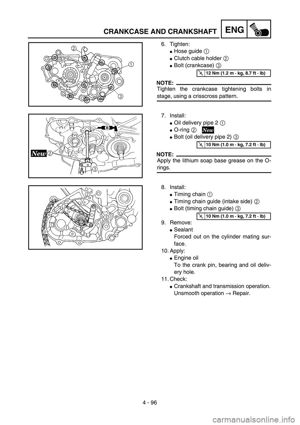
ENGCRANKCASE AND CRANKSHAFT
6. Tighten:
�Hose guide 1
�Clutch cable holder 2
�Bolt (crankcase) 3
NOTE:
Tighten the crankcase tightening bolts in
stage, using a crisscross pattern.
T R..12 Nm (1.2 m · kg, 8.7 ft · lb)
7. Install:
�Oil delivery pipe 2 1
�O-ring 2
�Bolt (oil delivery pipe 2) 3
NOTE:
Apply the lithium soap base grease on the O-
rings.
T R..10 Nm (1.0 m · kg, 7.2 ft · lb)
8. Install:
�Timing chain 1
�Timing chain guide (intake side) 2
�Bolt (timing chain guide) 3
9. Remove:
�Sealant
Forced out on the cylinder mating sur-
face.
10. Apply:
�Engine oil
To the crank pin, bearing and oil deliv-
ery hole.
11. Check:
�Crankshaft and transmission operation.
Unsmooth operation → Repair.
T R..10 Nm (1.0 m · kg, 7.2 ft · lb)


![YAMAHA WR 250F 2002 Owners Manual 4 - 89
ENGCRANKCASE AND CRANKSHAFT
Extent of removal Order Part name Q’ty Remarks
4 Bolt [L = 45 mm (1.77 in)] 6
Refer to “REMOVAL POINTS”. 5 Bolt [L = 55 mm (2.17 in)] 1
6 Bolt [L = 70 mm (2.76](/manual-img/51/52338/w960_52338-445.png "YAMAHA WR 250F 2002 Owners Manual 4 - 89
ENGCRANKCASE AND CRANKSHAFT
Extent of removal Order Part name Q’ty Remarks
4 Bolt [L = 45 mm (1.77 in)] 6
Refer to “REMOVAL POINTS”. 5 Bolt [L = 55 mm (2.17 in)] 1
6 Bolt [L = 70 mm (2.76")