2002 YAMAHA TDR 125 torque
[x] Cancel search: torquePage 37 of 94
6-1
EAU00462
PERIODIC MAINTENANCE AND MINOR REPAIR
6
EAU00464
Safety is an obligation of the owner.
Periodic inspection, adjustment and
lubrication will keep your vehicle in
the safest and most efficient condi-
tion possible. The most important
points of inspection, adjustment, and
lubrication are explained on the fol-
lowing pages.
The intervals given in the periodic
maintenance and lubrication chart
should be simply considered as a
general guide under normal riding
conditions. However, DEPENDING
ON THE WEATHER, TERRAIN,
GEOGRAPHICAL LOCATION, AND
INDIVIDUAL USE, THE MAINTE-
NANCE INTERVALS MAY NEED TO
BE SHORTENED.
EW000060
wIf you are not familiar with motor-
cycle maintenance work, have a
Yamaha dealer do it for you.
EAU03758
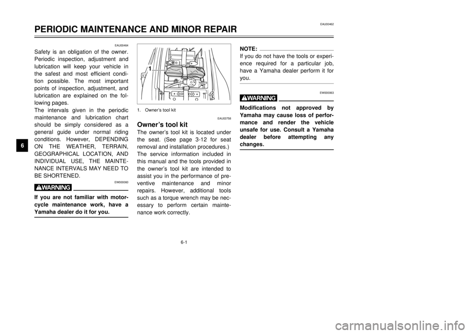
Owner’s tool kitThe owner’s tool kit is located under
the seat. (See page 3-12 for seat
removal and installation procedures.)
The service information included in
this manual and the tools provided in
the owner’s tool kit are intended to
assist you in the performance of pre-
ventive maintenance and minor
repairs. However, additional tools
such as a torque wrench may be nec-
essary to perform certain mainte-
nance work correctly.
NOTE:
If you do not have the tools or experi-
ence required for a particular job,
have a Yamaha dealer perform it for
you.
EW000063
wModifications not approved by
Yamaha may cause loss of perfor-
mance and render the vehicle
unsafe for use. Consult a Yamaha
dealer before attempting any
changes.
1
1. Owner’s tool kit
5AE-28199-E5 honbun 7/6/01 10:18 AM Page 36
Page 44 of 94
6-8
PERIODIC MAINTENANCE AND MINOR REPAIR
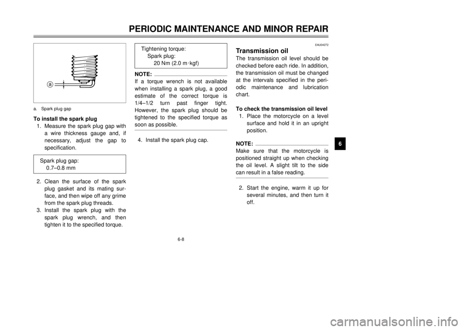
6 To install the spark plug
1. Measure the spark plug gap with
a wire thickness gauge and, if
necessary, adjust the gap to
specification.
2. Clean the surface of the spark
plug gasket and its mating sur-
face, and then wipe off any grime
from the spark plug threads.
3. Install the spark plug with the
spark plug wrench, and then
tighten it to the specified torque.
NOTE:
If a torque wrench is not available
when installing a spark plug, a good
estimate of the correct torque is
1/4–1/2 turn past finger tight.
However, the spark plug should be
tightened to the specified torque as
soon as possible.4. Install the spark plug cap.
EAU04272
Transmission oil
Transmission oil
The transmission oil level should be
checked before each ride. In addition,
the transmission oil must be changed
at the intervals specified in the peri-
odic maintenance and lubrication
chart.
To check the transmission oil level
1. Place the motorcycle on a level
surface and hold it in an upright
position.NOTE:
Make sure that the motorcycle is
positioned straight up when checking
the oil level. A slight tilt to the side
can result in a false reading.2. Start the engine, warm it up for
several minutes, and then turn it
off.
a
a. Spark plug gap
Spark plug gap:
0.7–0.8 mm
Tightening torque:
Spark plug:
20 Nm (2.0 m0kgf)
5AE-28199-E5 honbun 7/6/01 10:18 AM Page 43
Page 45 of 94
6-9
PERIODIC MAINTENANCE AND MINOR REPAIR
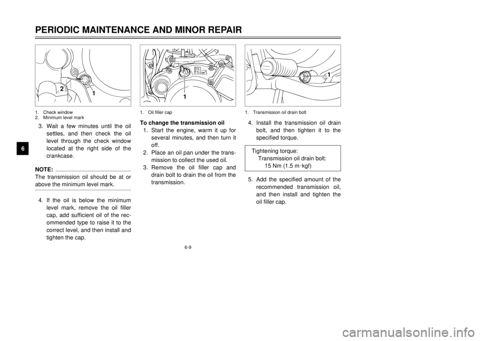
63. Wait a few minutes until the oil
settles, and then check the oil
level through the check window
located at the right side of the
crankcase.
NOTE:
The transmission oil should be at or
above the minimum level mark.4. If the oil is below the minimum
level mark, remove the oil filler
cap, add sufficient oil of the rec-
ommended type to raise it to the
correct level, and then install and
tighten the cap.To change the transmission oil
1. Start the engine, warm it up for
several minutes, and then turn it
off.
2. Place an oil pan under the trans-
mission to collect the used oil.
3. Remove the oil filler cap and
drain bolt to drain the oil from the
transmission.4. Install the transmission oil drain
bolt, and then tighten it to the
specified torque.
5. Add the specified amount of the
recommended transmission oil,
and then install and tighten the
oil filler cap.
1
2
1
1
1. Check window
2. Minimum level mark1. Oil filler cap 1. Transmission oil drain bolt
Tightening torque:
Transmission oil drain bolt:
15 Nm (1.5 m0kgf)
5AE-28199-E5 honbun 7/6/01 10:18 AM Page 44
Page 47 of 94
6-11
PERIODIC MAINTENANCE AND MINOR REPAIR
6
EW000067
wNever attempt to remove the radia-
tor cap when the engine is hot.NOTE:
If the engine overheats, see page
6-43 for further instructions.
EAU03746
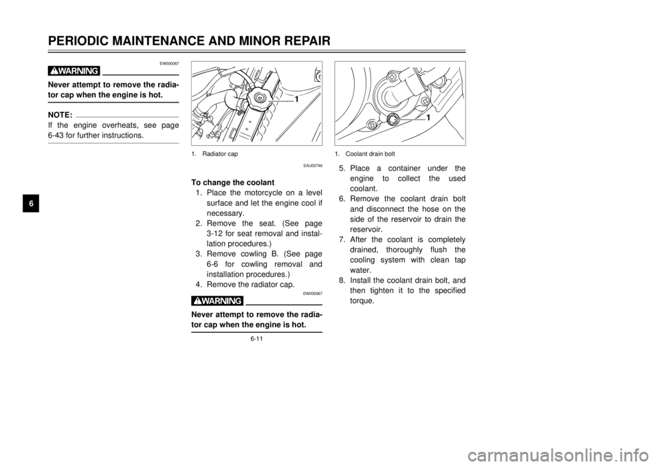
To change the coolant
1. Place the motorcycle on a level
surface and let the engine cool if
necessary.
2. Remove the seat. (See page
3-12 for seat removal and instal-
lation procedures.)
3. Remove cowling B. (See page
6-6 for cowling removal and
installation procedures.)
4. Remove the radiator cap.
EW000067
wNever attempt to remove the radia-
tor cap when the engine is hot.
5. Place a container under the
engine to collect the used
coolant.
6. Remove the coolant drain bolt
and disconnect the hose on the
side of the reservoir to drain the
reservoir.
7. After the coolant is completely
drained, thoroughly flush the
cooling system with clean tap
water.
8. Install the coolant drain bolt, and
then tighten it to the specified
torque.
1
1
1. Radiator cap 1. Coolant drain bolt
5AE-28199-E5 honbun 7/6/01 10:18 AM Page 46
Page 48 of 94
6-12
PERIODIC MAINTENANCE AND MINOR REPAIR
6
NOTE:
Check the washer for damage and
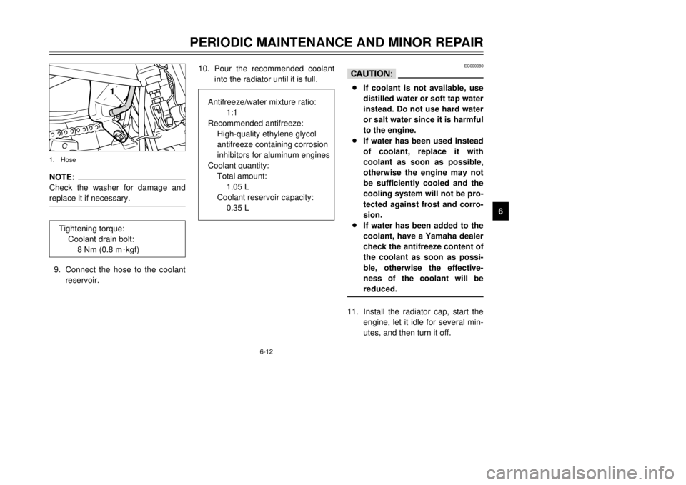
replace it if necessary.9. Connect the hose to the coolant
reservoir.10. Pour the recommended coolant
into the radiator until it is full.
EC000080
cC8If coolant is not available, use
distilled water or soft tap water
instead. Do not use hard water
or salt water since it is harmful
to the engine.
8If water has been used instead
of coolant, replace it with
coolant as soon as possible,
otherwise the engine may not
be sufficiently cooled and the
cooling system will not be pro-
tected against frost and corro-
sion.
8If water has been added to the
coolant, have a Yamaha dealer
check the antifreeze content of
the coolant as soon as possi-
ble, otherwise the effective-
ness of the coolant will be
reduced.11. Install the radiator cap, start the
engine, let it idle for several min-
utes, and then turn it off.
1
1. Hose
Tightening torque:
Coolant drain bolt:
8 Nm (0.8 m0kgf)
Antifreeze/water mixture ratio:
1:1
Recommended antifreeze:
High-quality ethylene glycol
antifreeze containing corrosion
inhibitors for aluminum engines
Coolant quantity:
Total amount:
1.05 L
Coolant reservoir capacity:
0.35 L
5AE-28199-E5 honbun 7/6/01 10:18 AM Page 47
Page 62 of 94
6-26
PERIODIC MAINTENANCE AND MINOR REPAIR
6
EAU03752
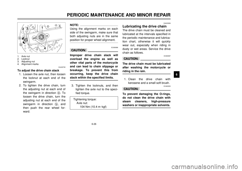
To adjust the drive chain slack
1. Loosen the axle nut, then loosen
the locknut at each end of the
swingarm.
2. To tighten the drive chain, turn
the adjusting nut at each end of
the swingarm in direction a. To
loosen the drive chain, turn the
adjusting nut at each end of the
swingarm in direction b, and
then push the rear wheel for-
ward.
NOTE:
Using the alignment marks on each
side of the swingarm, make sure that
both adjusting nuts are in the same
position for proper wheel alignment.
EC000096
cCImproper drive chain slack will
overload the engine as well as
other vital parts of the motorcycle
and can lead to chain slippage or
breakage. To prevent this from
occurring, keep the drive chain
slack within the specified limits.3. Tighten the locknuts, and then
tighten the axle nut to the speci-
fied torque.
EAU03006
Lubricating the drive chainThe drive chain must be cleaned and
lubricated at the intervals specified in
the periodic maintenance and lubrica-
tion chart, otherwise it will quickly
wear out, especially when riding in
dusty or wet areas. Service the drive
chain as follows.
EC000097
cCThe drive chain must be lubricated
after washing the motorcycle or
riding in the rain.1. Clean the drive chain with
kerosene and a small soft brush.
ECA00053
cCTo prevent damaging the O-rings,
do not clean the drive chain with
steam cleaners, high-pressure
washers or inappropriate solvents.
1
4
2
3
a
b1. Axle nut
2. Locknut
3. Adjusting nut
4. Alignment marks
Tightening torque:
Axle nut:
104 Nm (10.4 m0kgf)
5AE-28199-E5 honbun 7/6/01 10:18 AM Page 61
Page 74 of 94
6-38
PERIODIC MAINTENANCE AND MINOR REPAIR
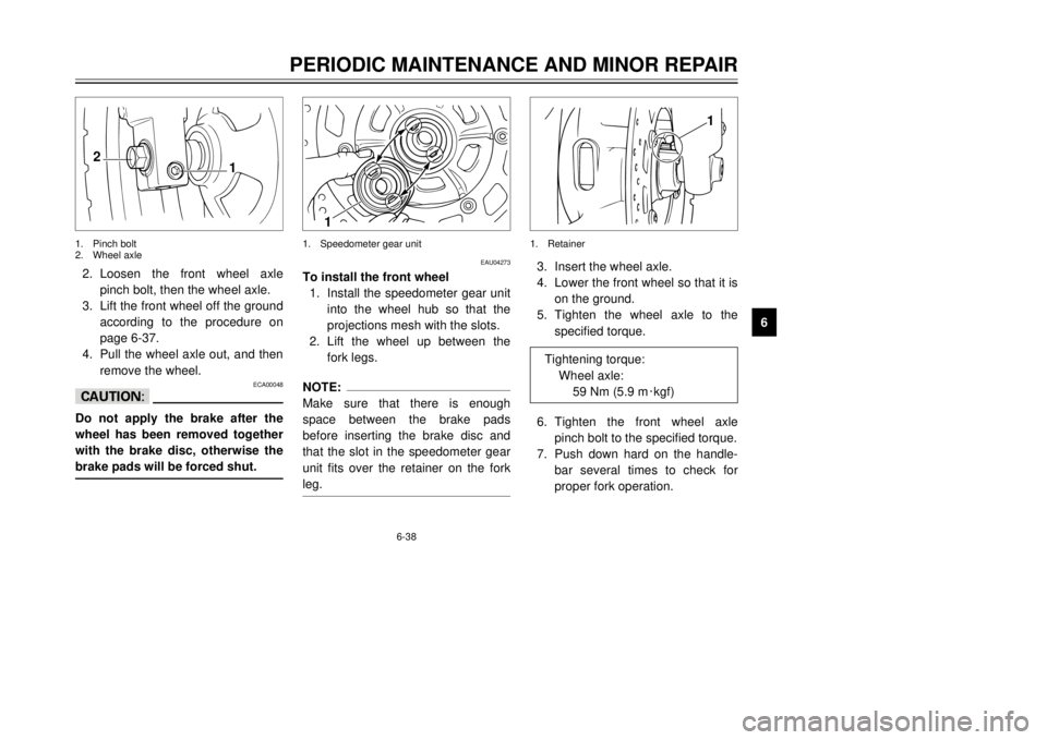
6 2. Loosen the front wheel axle
pinch bolt, then the wheel axle.
3. Lift the front wheel off the ground
according to the procedure on
page 6-37.
4. Pull the wheel axle out, and then
remove the wheel.
ECA00048
cCDo not apply the brake after the
wheel has been removed together
with the brake disc, otherwise the
brake pads will be forced shut.
EAU04273
To install the front wheel
Installing
1. Install the speedometer gear unit
into the wheel hub so that the
projections mesh with the slots.
2. Lift the wheel up between the
fork legs.NOTE:
Make sure that there is enough
space between the brake pads
before inserting the brake disc and
that the slot in the speedometer gear
unit fits over the retainer on the fork
leg.
3. Insert the wheel axle.
4. Lower the front wheel so that it is
on the ground.
5. Tighten the wheel axle to the
specified torque.
6. Tighten the front wheel axle
pinch bolt to the specified torque.
7. Push down hard on the handle-
bar several times to check for
proper fork operation.
2
1
1
1
1. Pinch bolt
2. Wheel axle1. Speedometer gear unit 1. Retainer
Tightening torque:
Wheel axle:
59 Nm (5.9 m0kgf)
5AE-28199-E5 honbun 7/6/01 10:18 AM Page 73
Page 75 of 94
6-39
PERIODIC MAINTENANCE AND MINOR REPAIR
68. Connect the speedometer cable.
EAU03755
Rear wheelTo remove the rear wheel
EW000122
w8It is advisable to have a
Yamaha dealer service the
wheel.
8Securely support the motorcy-
cle so that there is no danger
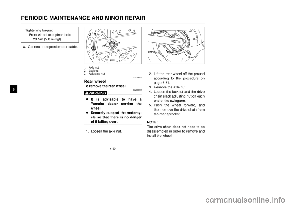
of it falling over.1. Loosen the axle nut.2. Lift the rear wheel off the ground
according to the procedure on
page 6-37.
3. Remove the axle nut.
4. Loosen the locknut and the drive
chain slack adjusting nut on each
end of the swingarm.
5. Push the wheel forward, and
then remove the drive chain from
the rear sprocket.
NOTE:
The drive chain does not need to be
disassembled in order to remove and
install the wheel.
1
2
3
1. Axle nut
2. Locknut
3. Adjusting nut
Tightening torque:
Front wheel axle pinch bolt:
20 Nm (2.0 m0kgf)
5AE-28199-E5 honbun 7/6/01 10:18 AM Page 74