Page 15 of 114
2-3
EAU00026
DESCRIPTION
2
1. Rear brake lever (page 3-13)
2. Left handlebar switches (page 3-10)
3. Front storage compartment A (page 3-17)
4. Coolant temperature gauge (page 3-5)
5. Tachometer (page 3-3)
6. Speedometer (page 3-3)
7. Multi-function display (page 3-5)8. Fuel gauge (page 3-4)
9. Right handlebar switches (page 3-12)
10. Front brake lever (page 3-12)
11. Throttle grip (page 6-23, 6-31)
12. Front storage compartment B (page 3-18)
13. Main switch/steering lock (page 3-1)
1
23
46578910
11
12 13
Controls and instruments
5SJ-28199-E0 1/24/02 6:14 PM Page 14
Page 16 of 114

INSTRUMENT AND CONTROL FUNCTIONSMain switch/steering lock ...................................................................3-1
Indicator lights ...................................................................................3-2
Speedometer .....................................................................................3-3
Tachometer .......................................................................................3-3
Fuel gauge .........................................................................................3-4
Coolant temperature gauge ...............................................................3-5
Multi-function display .........................................................................3-5
Anti-theft alarm (optional) ..................................................................3-9
Handlebar switches .........................................................................3-10
Front brake lever .............................................................................3-12
Rear brake lever ..............................................................................3-13
Fuel tank cap ...................................................................................3-13
Fuel ..................................................................................................3-14
Catalytic converter ...........................................................................3-15
Rider seat ........................................................................................3-16
Adjusting the rider seat ....................................................................3-17
Storage compartments ....................................................................3-17
Adjusting the shock absorber assemblies .......................................3-19
Sidestand .........................................................................................3-20
Ignition circuit cut-off system ...........................................................3-21
3
5SJ-28199-E0 1/24/02 6:14 PM Page 15
Page 21 of 114

3-5
INSTRUMENT AND CONTROL FUNCTIONS
3
EAU03124
Coolant temperature gaugeCoolant temperature gaugeThis gauge indicates the coolant tem-
perature when the main switch is on.
The engine operating temperature
will vary with changes in weather and
engine load. If the needle points to
the red mark, stop your scooter and
let the engine cool. (See page
6-19 for details.)
EC000002
cCDo not operate the engine if it is
overheated.
1
2
1. Coolant temperature gauge
2. Red mark
EAU04589
Multi-function displayDisplay, multi-functionThe multi-function display is
equipped with the following:
8a tripmeter (which shows the dis-
tance traveled since it was last
set to zero)
8a fuel tripmeter (which shows the
distance traveled when the fuel
level reaches approximately 2.0 L)
8an odometer (which shows the
total distance traveled)
8a clock
8an outside temperature display8a voltage display (which shows
the battery voltage)
NOTE:
8When the key is turned to “ON”,
all segments of the display come
on for a few seconds. During this
time, the multi-function display is
performing a self-test.
8Be sure to turn the key to “ON”
before using the “SELECT” and
“RESET” buttons.
1
23
1. Tripmeter
2. Odometer, fuel tripmeter
3. Clock, outside temperature and voltage
meter display
5SJ-28199-E0 1/24/02 6:14 PM Page 20
Page 22 of 114

3-6
INSTRUMENT AND CONTROL FUNCTIONS
3
Tripmeter “Trip”
To reset the tripmeter:
1. Push the “SELECT” button until
the voltage display appears, then
push the “SELECT” button one
more time and “Trip” starts flash-
ing.
2. Push the “RESET” button for at
least one second to reset the
tripmeter to zero.
NOTE:
8The tripmeter reset mode auto-
matically cancels after five sec-
onds. To return to the reset
mode, push the “SELECT” but-
ton again until “Trip” begins
flashing.
8To cancel the tripmeter reset
mode, push the “SELECT” but-
ton.
8If the tripmeter indicates “––––”,
have a Yamaha dealer check or
repair the multi-function display
as it may be faulty.
Odometer “Odo”
The odometer has two functions.
8It shows the total distance trav-
eled.
8It automatically changes to the
fuel tripmeter mode “Trip F”
when the fuel level reaches
approximately 2.0 L. (See “Fuel
tripmeter” for details.)NOTE:
If the odometer indicates “––––––”,
have a Yamaha dealer check or
repair the multi-function display as it
may be faulty.
5SJ-28199-E0 1/24/02 6:14 PM Page 21
Page 23 of 114
3-7
INSTRUMENT AND CONTROL FUNCTIONS
3
Fuel tripmeter “Trip F”
When the fuel level reaches approxi-
mately 2.0 L, the odometer display
automatically changes to the fuel trip-
meter mode “Trip F” and starts count-
ing the distance traveled from that
point. After refueling and traveling
5 km, the odometer display returns to
“Odo”.
To return to the odometer mode
before refueling, push the “SELECT”
button until “Trip F” begins flashing
(“Trip F” will only flash for five sec-
onds). While “Trip F” is flashing, push
the “RESET” button for at least one
second and the display will return to
the odometer mode. From that time,
both “Trip” and “Odo” are displayed
until you refuel and travel 5 km.NOTE:
The display cannot be changed back
to “Trip F” after pushing the “RESET”
button.
Clock
To set the clock1. Push the “SELECT” button until
the clock is displayed.
2. Push the “SELECT” button and
“RESET” button together for at
least two seconds.
5SJ-28199-E0 1/24/02 6:14 PM Page 22
Page 24 of 114
3-8
INSTRUMENT AND CONTROL FUNCTIONS
3
3. When the hour digits start flash-
ing, push the “RESET” button to
set the hours.
4. Push the “SELECT” button, and
the minute digits will start flash-
ing.
5. Push the “RESET” button to set
the minutes.
6. Push the “SELECT” button and
then release it to start the clock.
Outside temperature display
This display shows the outside tem-
perature from –10.0 °C to 50.0 °C in
0.5 °increments.
5SJ-28199-E0 1/24/02 6:14 PM Page 23
Page 25 of 114

3-9
INSTRUMENT AND CONTROL FUNCTIONS
3
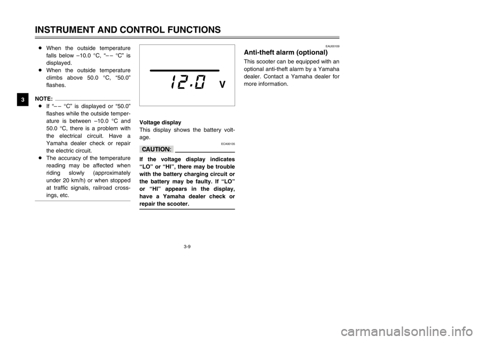
Voltage display
This display shows the battery volt-
age.
ECA00135
cCIf the voltage display indicates
“LO” or “HI”, there may be trouble
with the battery charging circuit or
the battery may be faulty. If “LO”
or “HI” appears in the display,
have a Yamaha dealer check or
repair the scooter.
EAU00109
Anti-theft alarm (optional)Anti-theft alarm (optional)This scooter can be equipped with an
optional anti-theft alarm by a Yamaha
dealer. Contact a Yamaha dealer for
more information. 8When the outside temperature
falls below –10.0 °C, “– – °C” is
displayed.
8When the outside temperature
climbs above 50.0 °C, “50.0”
flashes.
NOTE:
8If “– – °C” is displayed or “50.0”
flashes while the outside temper-
ature is between –10.0 °C and
50.0 °C, there is a problem with
the electrical circuit. Have a
Yamaha dealer check or repair
the electric circuit.
8The accuracy of the temperature
reading may be affected when
riding slowly (approximately
under 20 km/h) or when stopped
at traffic signals, railroad cross-
ings, etc.
5SJ-28199-E0 1/24/02 6:14 PM Page 24