2002 YAMAHA MAJESTY 250 fuel cap
[x] Cancel search: fuel capPage 13 of 114

2-1
EAU00026
DESCRIPTIONPart locations
2
1. Rear storage compartment (page 3-18)
2. Grab bar (page 5-2)
3. Shock absorber spring preload
adjusting ring (page 3-19)
4. Air filter element (page 6-21)5. V-belt case air filter element (page 6-22)
6. Centerstand (page 6-31)
7. Sidestand (page 3-20, 6-31)
8. Fuel tank cap (page 3-13)
12
3
4 5 6 7
8
Left view
5SJ-28199-E0 1/24/02 6:14 PM Page 12
Page 16 of 114
INSTRUMENT AND CONTROL FUNCTIONSMain switch/steering lock ...................................................................3-1
Indicator lights ...................................................................................3-2
Speedometer .....................................................................................3-3
Tachometer .......................................................................................3-3
Fuel gauge .........................................................................................3-4
Coolant temperature gauge ...............................................................3-5
Multi-function display .........................................................................3-5
Anti-theft alarm (optional) ..................................................................3-9
Handlebar switches .........................................................................3-10
Front brake lever .............................................................................3-12
Rear brake lever ..............................................................................3-13
Fuel tank cap ...................................................................................3-13
Fuel ..................................................................................................3-14
Catalytic converter ...........................................................................3-15
Rider seat ........................................................................................3-16
Adjusting the rider seat ....................................................................3-17
Storage compartments ....................................................................3-17
Adjusting the shock absorber assemblies .......................................3-19
Sidestand .........................................................................................3-20
Ignition circuit cut-off system ...........................................................3-21
3
5SJ-28199-E0 1/24/02 6:14 PM Page 15
Page 29 of 114
3-13
INSTRUMENT AND CONTROL FUNCTIONS
3
EAU00163
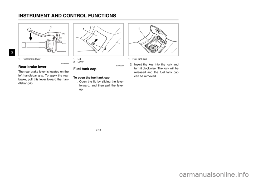
Rear brake leverBrake lever, rearThe rear brake lever is located on the
left handlebar grip. To apply the rear
brake, pull this lever toward the han-
dlebar grip.
1
1. Rear brake lever
2. Insert the key into the lock and
turn it clockwise. The lock will be
released and the fuel tank cap
can be removed.
1
1. Fuel tank cap
EAU03090
Fuel tank capFuel tank capTo open the fuel tank cap
1. Open the lid by sliding the lever
forward, and then pull the lever
up.
1
2
1. Lid
2. Lever
5SJ-28199-E0 1/24/02 6:14 PM Page 28
Page 30 of 114
3-14
INSTRUMENT AND CONTROL FUNCTIONS
3
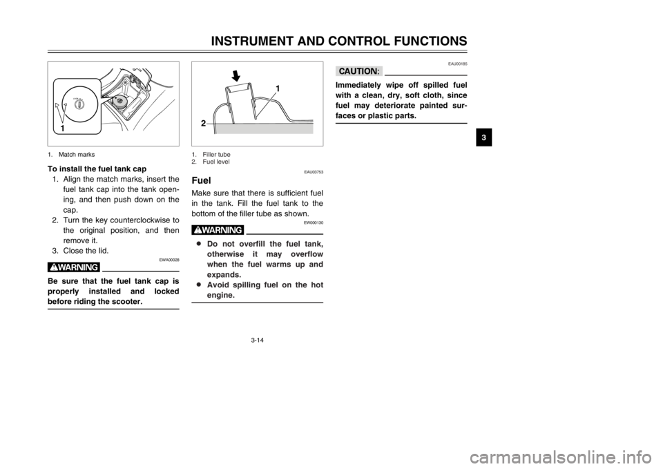
To install the fuel tank cap
1. Align the match marks, insert the
fuel tank cap into the tank open-
ing, and then push down on the
cap.
2. Turn the key counterclockwise to
the original position, and then
remove it.
3. Close the lid.
EWA00028
wBe sure that the fuel tank cap is
properly installed and locked
before riding the scooter.
1
1. Match marks
EAU03753
FuelFuelMake sure that there is sufficient fuel
in the tank. Fill the fuel tank to the
bottom of the filler tube as shown.
EW000130
w8 8
Do not overfill the fuel tank,
otherwise it may overflow
when the fuel warms up and
expands.
8 8
Avoid spilling fuel on the hot
engine.
1
2
1. Filler tube
2. Fuel level
EAU00185
cCImmediately wipe off spilled fuel
with a clean, dry, soft cloth, since
fuel may deteriorate painted sur-
faces or plastic parts.
5SJ-28199-E0 1/24/02 6:14 PM Page 29
Page 31 of 114
3-15
INSTRUMENT AND CONTROL FUNCTIONS
3
EAU04284
ECA00104
cCUse only unleaded gasoline. The
use of leaded gasoline will cause
severe damage to internal engine
parts, such as the valves and pis-
ton rings, as well as to the exhaust
system.
EAU03098
Catalytic converterCatalytic converterThis scooter is equipped with a cat-
alytic converter in the muffler.
EW000128
wThe exhaust system is hot after
operation. Make sure that the
exhaust system has cooled down
before doing any maintenance
work.
Your Yamaha engine has been
designed to use regular unleaded
gasoline with a research octane num-
ber of 91 or higher. If knocking (or
pinging) occurs, use a gasoline of a
different brand or premium unleaded
fuel. Use of unleaded fuel will extend
spark plug life and reduce mainte-
nance costs. Recommended fuel:
REGULAR UNLEADED
GASOLINE ONLY
Fuel tank capacity:
Total amount:
12 L
5SJ-28199-E0 1/24/02 6:14 PM Page 30
Page 100 of 114
7-4
SCOOTER CARE AND STORAGE
7
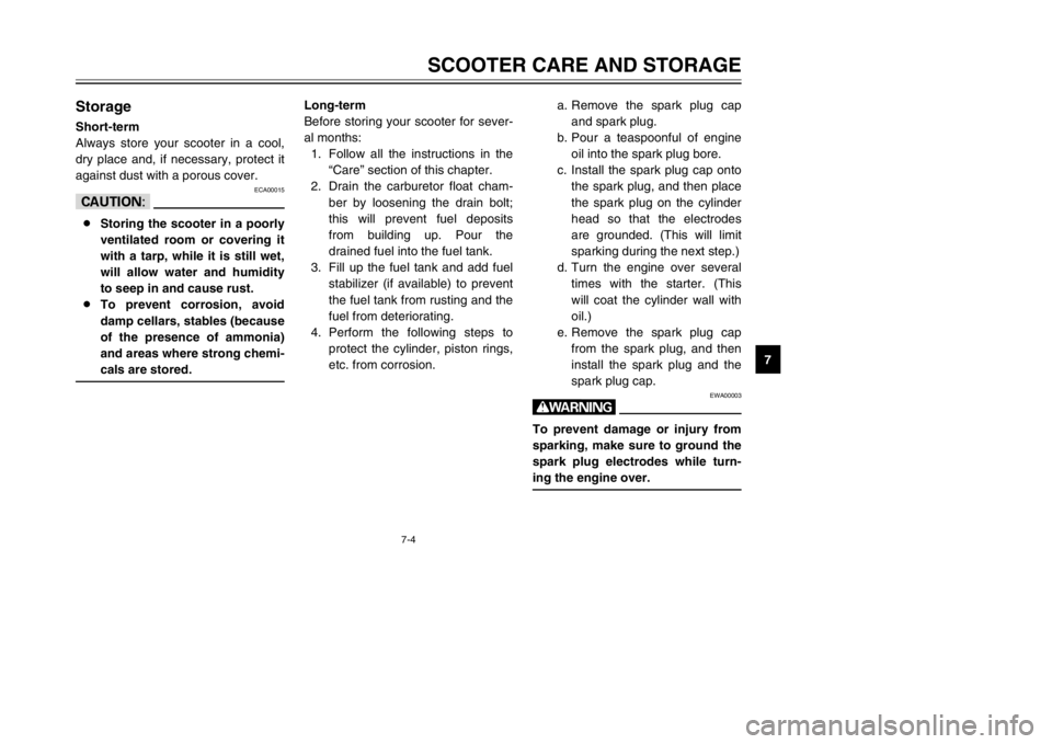
StorageStorageShort-term
Always store your scooter in a cool,
dry place and, if necessary, protect it
against dust with a porous cover.
ECA00015
cC8Storing the scooter in a poorly
ventilated room or covering it
with a tarp, while it is still wet,
will allow water and humidity
to seep in and cause rust.
8To prevent corrosion, avoid
damp cellars, stables (because
of the presence of ammonia)
and areas where strong chemi-
cals are stored.
Long-term
Before storing your scooter for sever-
al months:
1. Follow all the instructions in the
“Care” section of this chapter.
2. Drain the carburetor float cham-
ber by loosening the drain bolt;
this will prevent fuel deposits
from building up. Pour the
drained fuel into the fuel tank.
3. Fill up the fuel tank and add fuel
stabilizer (if available) to prevent
the fuel tank from rusting and the
fuel from deteriorating.
4. Perform the following steps to
protect the cylinder, piston rings,
etc. from corrosion.a. Remove the spark plug cap
and spark plug.
b. Pour a teaspoonful of engine
oil into the spark plug bore.
c. Install the spark plug cap onto
the spark plug, and then place
the spark plug on the cylinder
head so that the electrodes
are grounded. (This will limit
sparking during the next step.)
d. Turn the engine over several
times with the starter. (This
will coat the cylinder wall with
oil.)
e. Remove the spark plug cap
from the spark plug, and then
install the spark plug and the
spark plug cap.
EWA00003
wTo prevent damage or injury from
sparking, make sure to ground the
spark plug electrodes while turn-
ing the engine over.
5SJ-28199-E0 1/24/02 6:14 PM Page 99
Page 104 of 114

8-2
SPECIFICATIONS
8
Final gear case oil
Type Engine oil SAE 10W-30
(API SE)
Total amount 0.25 L
Radiator capacity
(including all routes)1.4 L
Air filterWet type element
Fuel
Type REGULAR UNLEADED
GASOLINE ONLY
Fuel tank capacity 12 L
Carburetor
Manufacturer TEIKEI
Model × quantity Y28V-1E × 1
Spark plug
Manufacturer/model NGK/DR8EA
Spark plug gap 0.6–0.7 mm
Clutch typeDry, centrifugal automatic
Transmission
Primary reduction system Helical gear
Primary reduction ratio 40/15 (2.666)
Secondary reduction system Helical gear
Secondary reduction ratio 38/15 (2.533)Transmission type V-belt automatic
Operation Centrifugal automatic type
Chassis
Frame type Steel tube underbone
Caster angle 28°
Trail 103 mm
Tires
Front
Type Tubeless
Size 110/90-12 64L
Manufacturer/ IRC/MB67
model MICHELIN/BOPPER
Rear
Type Tubeless
Size 130/70-12 62L
Manufacturer/ IRC/MB67
model MICHELIN/BOPPER
Maximum load* 185 kg
Air pressure (cold tire)
up to 90 kg load*
Front175 kPa (1.75 kgf/cm
2, 1.75 bar)
Rear200 kPa (2.00 kgf/cm2, 2.00 bar)
5SJ-28199-E0 1/24/02 6:14 PM Page 103
Page 111 of 114
INDEX
F
Final transmission oil ............................6-18
Front and rear brake lever free play,
adjusting ............................................6-27
Front fork, checking ..............................6-32
Fuel ......................................................3-14
Fuel consumption, tips for reducing .......5-4
Fuel gauge .............................................3-4
Fuel tank cap ........................................3-13
Fuses, replacing ...................................6-36
H
Handlebar switches ..............................3-10
Dimmer switch ...................................3-10
Engine stop switch .............................3-12
Headlight variations ...........................3-11
Horn switch ........................................3-10
Pass switch ........................................3-10
Start switch ........................................3-12
Turn signal switch ..............................3-10
Headlight bulb, replacing ......................6-37
I
Identification numbers ............................9-1
Ignition circuit cut-off system ................3-21
Indicator lights ........................................3-2
High beam indicator light .....................3-2
Oil change indicator light .....................3-2
Turn signal indicator lights ...................3-2
K
Key identification number .......................9-1
L
License plate light bulb, replacing ........6-41
M
Main switch/steering lock .......................3-1
Model label .............................................9-2
P
Parking ...................................................5-5
Part locations ..........................................2-1
Periodic maintenance and lubrication
chart .....................................................6-3
Pre-operation check list ..........................4-1
R
Rider seat .............................................3-16
Rider seat, adjusting .............................3-17
S
Safe-riding points ...................................1-2
Shock absorber assemblies,
adjusting ............................................3-19
Sidestand .............................................3-20
Spark plug, checking ............................6-12
Specifications .........................................8-1
Speedometer ..........................................3-3
Starting off ..............................................5-2
Starting the engine .................................5-1
Steering, checking ................................6-33
Storage ...................................................7-4
Storage compartments .........................3-17
A
Acceleration and deceleration ................5-3
Air filter and V-belt case air filter
elements, cleaning .............................6-21
Air flow louver .......................................6-23
Anti-theft alarm (optional) .......................3-9
B
Battery ..................................................6-34
Battery cover removal ..........................6-34
Brake fluid level, checking ....................6-29
Brake fluid, changing ............................6-30
Brake lever, front ..................................3-12
Brake lever, rear ...................................3-13
Brake levers, lubricating .......................6-31
Braking ...................................................5-3
C
Cables, checking and lubricating ..........6-30
Care ........................................................7-1
Catalytic converter ................................3-15
Centerstand and sidestand, checking
and lubricating ...................................6-31
Conversion table ....................................8-5
Coolant .................................................6-19
Coolant temperature gauge ....................3-5
Cowlings and panel, removing and
installing ...............................................6-6
E
Engine break-in ......................................5-4
Engine oil ..............................................6-14
5SJ-28199-E0 1/24/02 6:14 PM Page 110