Page 599 of 1690
A62183
Cut Position
Pry
A62184
SST
A62837SST
A64005
± ENGINE MECHANICALTIMING CHAIN OR BELT COVER OIL
SEAL (1ZZ±FE/3ZZ±FE)14±97
AVENSIS REPAIR MANUAL (RM1018E)
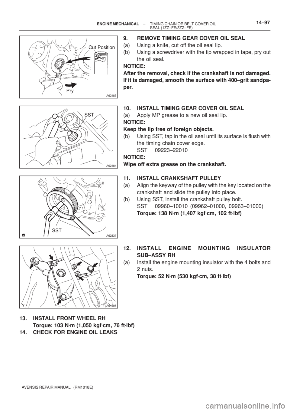
9. REMOVE TIMING GEAR COVER OIL SEAL
(a) Using a knife, cut off the oil seal lip.
(b) Using a screwdriver with the tip wrapped in tape, pry out
the oil seal.
NOTICE:
After the removal, check if the crankshaft is not damaged.
If it is damaged, smooth the surface with 400±grit sandpa-
per.
10. INSTALL TIMING GEAR COVER OIL SEAL
(a) Apply MP grease to a new oil seal lip.
NOTICE:
Keep the lip free of foreign objects.
(b) Using SST, tap in the oil seal until its surface is flush with
the timing chain cover edge.
SST 09223±22010
NOTICE:
Wipe off extra grease on the crankshaft.
11. INSTALL CRANKSHAFT PULLEY
(a) Align the keyway of the pulley with the key located on the
crankshaft and slide the pulley into place.
(b) Using SST, install the crankshaft pulley bolt.
SST 09960±10010 (09962±01000, 09963±01000)
Torque: 138 N�m (1,407 kgf�cm, 102 ft�lbf)
12. INSTALL ENGINE MOUNTING INSULATOR
SUB±ASSY RH
(a) Install the engine mounting insulator with the 4 bolts and
2 nuts.
Torque: 52 N�m (530 kgf�cm, 38 ft�lbf)
13. INSTALL FRONT WHEEL RH
Torque: 103 N�m (1,050 kgf�cm, 76 ft�lbf)
14. CHECK FOR ENGINE OIL LEAKS
Page 601 of 1690
A77418
Cut Position
A77419
SST
A77420
SST
SST
±
ENGINE MECHANICAL TIMING GEAR CASE OR TIMING CHAIN CASE OIL
SEAL(1AZ±FE)14±179
AVENSIS REPAIR MANUAL (RM1018E)
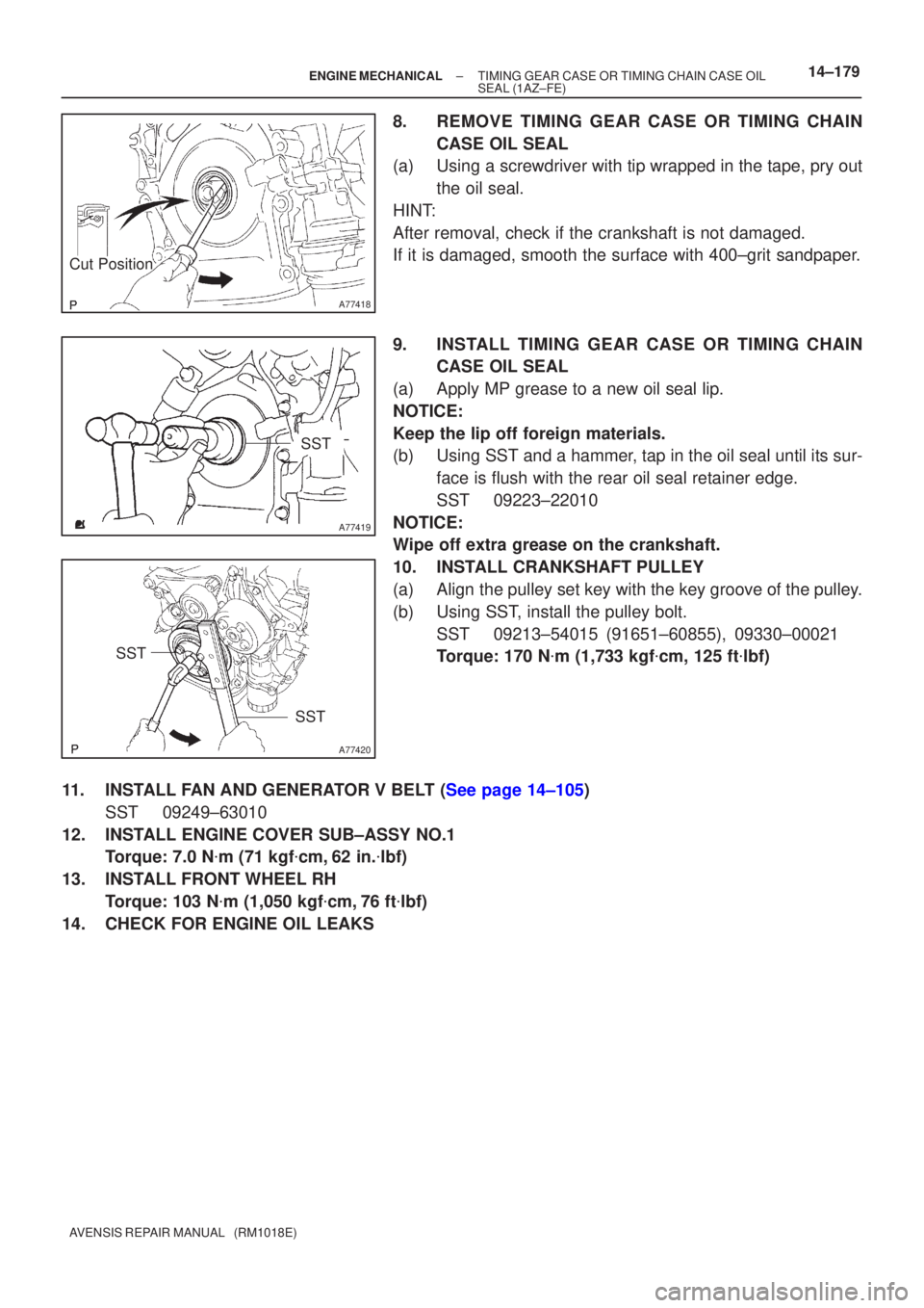
8.REMOVE TIMING GEAR CASE OR TIMING CHAIN
CASE OIL SEAL
(a)Using a screwdriver with tip wrapped in the tape, pry out
the oil seal.
HINT:
After removal, check if the crankshaft is not damaged.
If it is damaged, smooth the surface with 400±grit sandpaper.
9.INSTALL TIMING GEAR CASE OR TIMING CHAIN CASE OIL SEAL
(a)Apply MP grease to a new oil seal lip.
NOTICE:
Keep the lip off foreign materials.
(b)Using SST and a hammer, tap in the oil seal until its sur- face is flush with the rear oil seal retainer edge.
SST09223±22010
NOTICE:
Wipe off extra grease on the crankshaft.
10.INSTALL CRANKSHAFT PULLEY
(a)Align the pulley set key with the key groove of the pulley.
(b)Using SST, install the pulley bolt. SST09213±54015 (91651±60855), 09330±00021
Torque: 170 N �m (1,733 kgf �cm, 125 ft �lbf)
11.INSTALL FAN AND GENERATOR V BELT (See page 14±105) SST 09249±63010
12. INSTALL ENGINE COVER SUB±ASSY NO.1 Torque: 7.0 N �m (71 kgf �cm, 62 in. �lbf)
13. INSTALL FRONT WHEEL RH Torque: 103 N �m (1,050 kgf �cm, 76 ft �lbf)
14. CHECK FOR ENGINE OIL LEAKS
Page 603 of 1690
Cut Position
A13332
A77419
SST
A13697
SST
SST
14±264
±
ENGINE MECHANICAL TIMING GEAR CASE OR TIMING CHAIN CASE OIL
SEAL(1AZ±FSE)
AVENSIS REPAIR MANUAL (RM1018E)
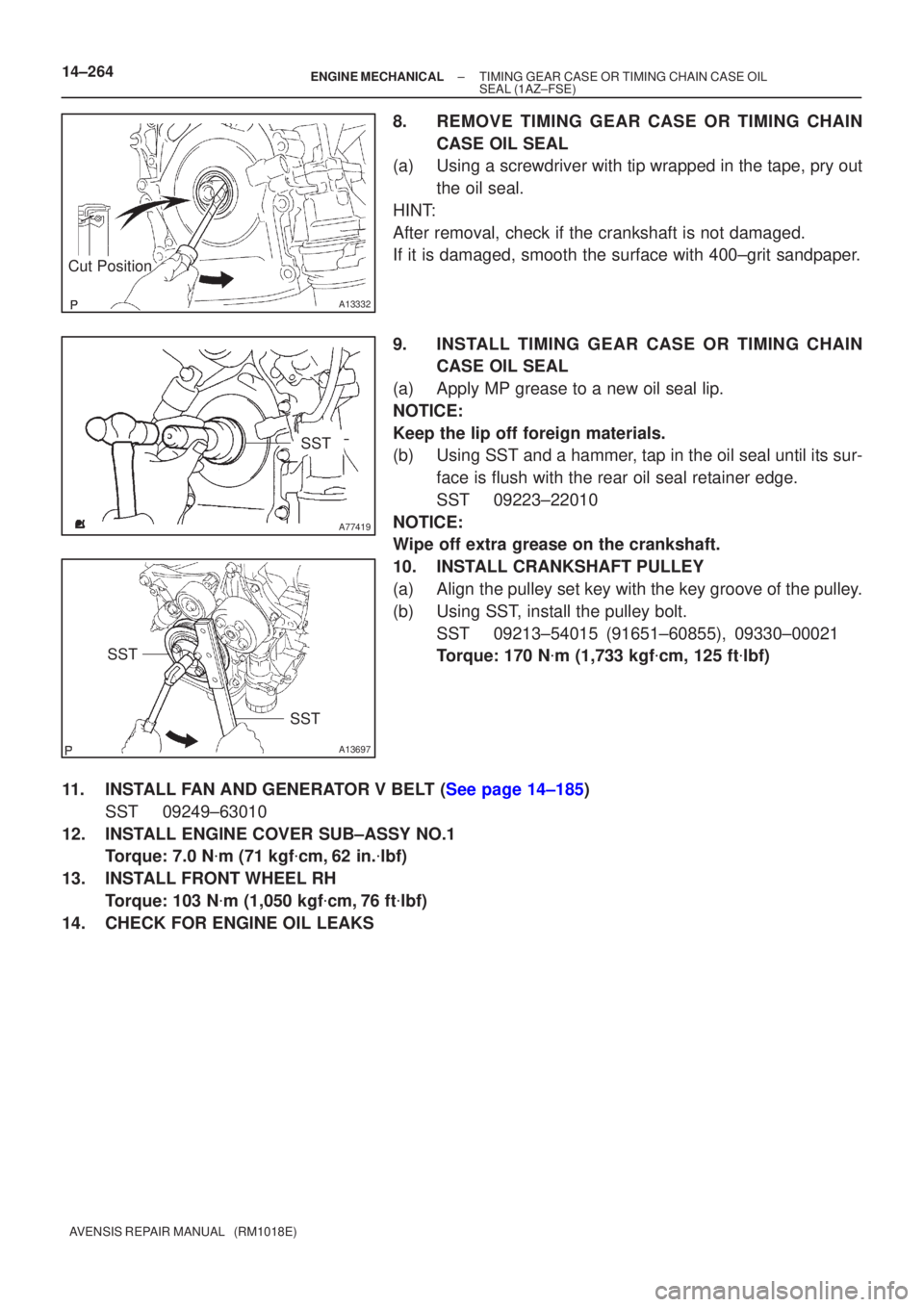
8.REMOVE TIMING GEAR CASE OR TIMING CHAIN CASE OIL SEAL
(a)Using a screwdriver with tip wrapped in the tape, pry out
the oil seal.
HINT:
After removal, check if the crankshaft is not damaged.
If it is damaged, smooth the surface with 400±grit sandpaper.
9.INSTALL TIMING GEAR CASE OR TIMING CHAIN CASE OIL SEAL
(a)Apply MP grease to a new oil seal lip.
NOTICE:
Keep the lip off foreign materials.
(b)Using SST and a hammer, tap in the oil seal until its sur- face is flush with the rear oil seal retainer edge.
SST09223±22010
NOTICE:
Wipe off extra grease on the crankshaft.
10.INSTALL CRANKSHAFT PULLEY
(a)Align the pulley set key with the key groove of the pulley.
(b)Using SST, install the pulley bolt. SST09213±54015 (91651±60855), 09330±00021
Torque: 170 N �m (1,733 kgf �cm, 125 ft �lbf)
11.INSTALL FAN AND GENERATOR V BELT (See page 14±185) SST 09249±63010
12. INSTALL ENGINE COVER SUB±ASSY NO.1 Torque: 7.0 N �m (71 kgf �cm, 62 in. �lbf)
13. INSTALL FRONT WHEEL RH Torque: 103 N �m (1,050 kgf �cm, 76 ft �lbf)
14. CHECK FOR ENGINE OIL LEAKS
Page 698 of 1690
C80880
F13686
26±14
±
FRONT SUSPENSION FRONT SHOCK ABSORBER WITH COIL SPRING
AVENSIS REPAIR MANUAL (RM1018E)
(d) Install the flexible hose and ABS speed sensor wire har- ness bracket with the bolt.
Torque: 19 N �m (192 kgf �cm, 14 ft �lbf)
25. INSTALL FRONT STABILIZER LINK ASSY LH
(a) Install the stabilizer bar link with the nut. Torque: 74 N �m (755 kgf �cm, 55 ft �lbf)
HINT:
If the ball joint turns together with the nut, use a hexagon (6 mm)
wrench to hold the stud.
26. INSTALL FRONT WHEEL Torque: 103 N �m (1,050 kgf �cm, 76 ft �lbf)
27.INSPECT AND ADJUST FRONT WHEEL ALIGNMENT (See page 26±6)
Page 707 of 1690
C80293
F13686
C80889
±
FRONT SUSPENSION FRONT SUSPENSION ARM SUB±ASSY LOWER NO.1
LH (ATM)26±19
AVENSIS REPAIR MANUAL (RM1018E)
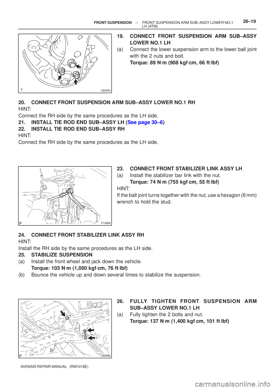
19. CONNECT FRONT SUSPENSION ARM SUB±ASSY
LOWER NO.1 LH
(a) Connect the lower suspension arm to the lower ball joint
with the 2 nuts and bolt.
Torque: 89 N �m (908 kgf �cm, 66 ft �lbf)
20. CONNECT FRONT SUSPENSION ARM SUB±ASSY LOWER NO.1 RH
HINT:
Connect the RH side by the same procedures as the LH side.
21.INSTALL TIE ROD END SUB±ASSY LH (See page 30±6)
22. INSTALL TIE ROD END SUB±ASSY RH
HINT:
Connect the RH side by the same procedures as the LH side. 23. CONNECT FRONT STABILIZER LINK ASSY LH
(a) Install the stabilizer bar link with the nut.Torque: 74 N �m (755 kgf �cm, 55 ft �lbf)
HINT:
If the ball joint turns together with the nut, use a hexagon (6 mm)
wrench to hold the stud.
24. CONNECT FRONT STABILIZER LINK ASSY RH
HINT:
Install the RH side by the same procedures as the LH side.
25. STABILIZE SUSPENSION
(a) Install the front wheel and jack down the vehicle. Torque: 103 N �m (1,050 kgf �cm, 76 ft �lbf)
(b) Bounce the vehicle up and down several times to stabilize the suspension\
.
26. FULLY TIGHTEN FRONT SUSPENSION ARMSUB±ASSY LOWER NO.1 LH
(a) Fully tighten the 2 bolts and nut.
Torque: 137 N �m (1,400 kgf �cm, 101 ft �lbf)
Page 710 of 1690
C80889
F41742
F13686
C80889
26±22± FRONT SUSPENSIONFRONT SUSPENSION ARM SUB±ASSY LOWER NO.1
LH (MTM)
AVENSIS REPAIR MANUAL (RM1018E)
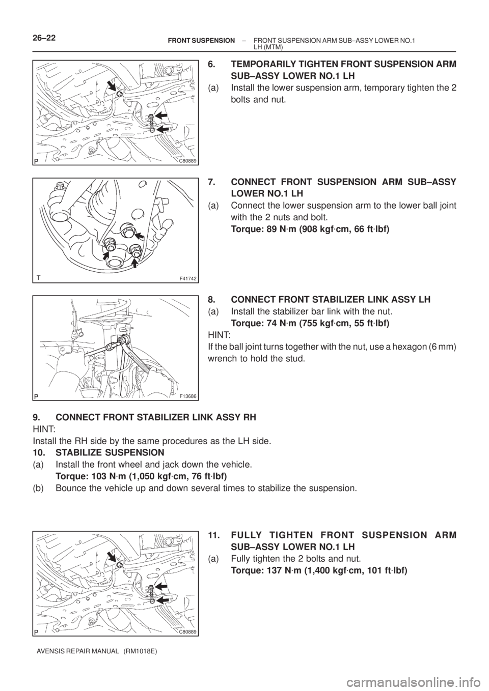
6. TEMPORARILY TIGHTEN FRONT SUSPENSION ARM
SUB±ASSY LOWER NO.1 LH
(a) Install the lower suspension arm, temporary tighten the 2
bolts and nut.
7. CONNECT FRONT SUSPENSION ARM SUB±ASSY
LOWER NO.1 LH
(a) Connect the lower suspension arm to the lower ball joint
with the 2 nuts and bolt.
Torque: 89 N�m (908 kgf�cm, 66 ft�lbf)
8. CONNECT FRONT STABILIZER LINK ASSY LH
(a) Install the stabilizer bar link with the nut.
Torque: 74 N�m (755 kgf�cm, 55 ft�lbf)
HINT:
If the ball joint turns together with the nut, use a hexagon (6 mm)
wrench to hold the stud.
9. CONNECT FRONT STABILIZER LINK ASSY RH
HINT:
Install the RH side by the same procedures as the LH side.
10. STABILIZE SUSPENSION
(a) Install the front wheel and jack down the vehicle.
Torque: 103 N�m (1,050 kgf�cm, 76 ft�lbf)
(b) Bounce the vehicle up and down several times to stabilize the suspension.
11. FULLY TIGHTEN FRONT SUSPENSION ARM
SUB±ASSY LOWER NO.1 LH
(a) Fully tighten the 2 bolts and nut.
Torque: 137 N�m (1,400 kgf�cm, 101 ft�lbf)
Page 713 of 1690
2600L±02
F44617
Front:AB
F44618
Rear:
C D
SA3213
A
D B
Front
C
F44619
26±6
±
FRONT SUSPENSION FRONT WHEEL ALIGNMENT
AVENSIS REPAIR MANUAL (RM1018E)
FRONT WHEEL ALIGNMENT
ADJUSTMENT
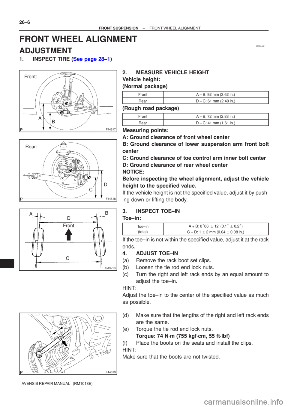
1.INSPECT TIRE (See page 28±1) 2. MEASURE VEHICLE HEIGHT
Vehicle height:
(Normal package)
FrontA ± B: 92 mm (3.62 in.)
RearD ± C: 61 mm (2.40 in.)
(Rough road package)
FrontA ± B: 72 mm (2.83 in.)
RearD ± C: 41 mm (1.61 in.)
Measuring points:
A: Ground clearance of front wheel center
B: Ground clearance of lower suspension arm front bolt
center
C: Ground clearance of toe control arm inner bolt center
D: Ground clearance of rear wheel center
NOTICE:
Before inspecting the wheel alignment, adjust the vehicle
height to the specified value.
If the vehicle height is not the specified value, adjust it by push-
ing down or lifting the body.
3. INSPECT TOE±IN
Toe±in:
Toe±in(total)A + B: 0 �06' � 12' (0.1 � � 0.2 �)
C ± D: 1 � 2 mm (0.04 � 0.08 in.)
If the toe±in is not within the specified value, adjust it at the rack
ends.
4. ADJUST TOE±IN
(a) Remove the rack boot set clips.
(b) Loosen the tie rod end lock nuts.
(c) Turn the right and left rack ends by an equal amount to
adjust the toe±in.
HINT:
Adjust the toe±in to the center of the specified value as much
as possible.
(d) Make sure that the lengths of the right and left rack ends are the same.
(e) Torque the tie rod end lock nuts.
Torque: 74 N´m (755 kgf´cm, 55 ft´lbf)
(f) Place the boots on the seats and install the clips.
HINT:
Make sure that the boots are not twisted.
Page 716 of 1690
F44962
+
±
F13685
1
2
F12938
Bolt
Adjusting
ValueSet BoltAdjusting Bolt90105±17008 90105±17009
90105±17010 90105±17011
121212121 Dot
2 Dots3 Dots
±1�30' ± ±1�15'
±1�15' ± ±1�00'
±1�00' ± ±45'
±45' ± ±30'
±30' ± ±15'
0' ± 15'
15' ± 30'
30' ± 45'
45' ± 1����
1�00' ± 1�15' ±15' ± 0'
1�15' ± 1�30'
± FRONT SUSPENSIONFRONT WHEEL ALIGNMENT
26±9
AVENSIS REPAIR MANUAL (RM1018E)
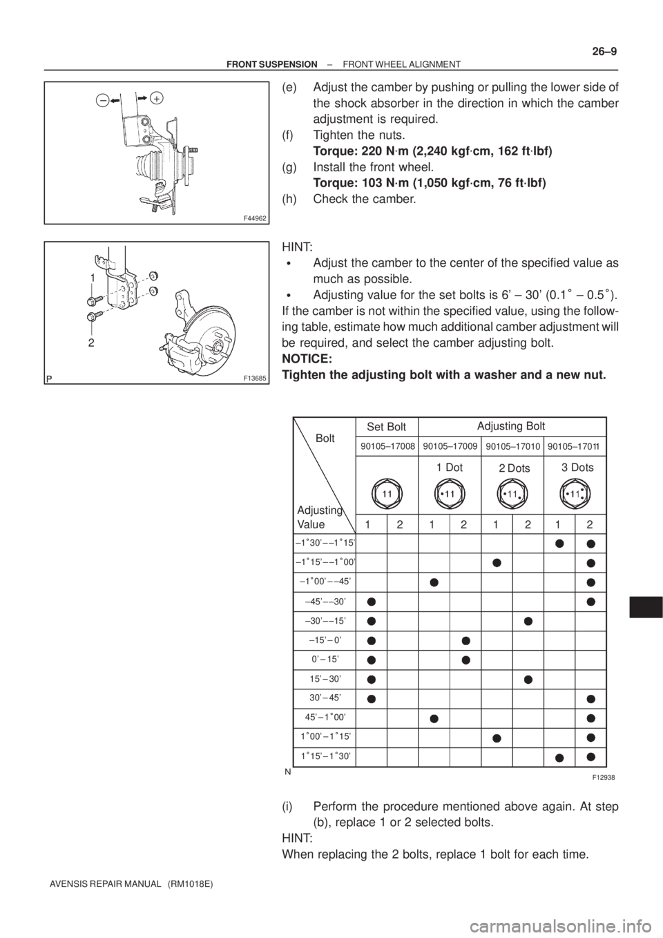
(e) Adjust the camber by pushing or pulling the lower side of
the shock absorber in the direction in which the camber
adjustment is required.
(f) Tighten the nuts.
Torque: 220 N�m (2,240 kgf�cm, 162 ft�lbf)
(g) Install the front wheel.
Torque: 103 N´m (1,050 kgf´cm, 76 ft´lbf)
(h) Check the camber.
HINT:
�Adjust the camber to the center of the specified value as
much as possible.
�Adjusting value for the set bolts is 6' ± 30' (0.1� ± 0.5�).
If the camber is not within the specified value, using the follow-
ing table, estimate how much additional camber adjustment will
be required, and select the camber adjusting bolt.
NOTICE:
Tighten the adjusting bolt with a washer and a new nut.
(i) Perform the procedure mentioned above again. At step
(b), replace 1 or 2 selected bolts.
HINT:
When replacing the 2 bolts, replace 1 bolt for each time.