Page 1082 of 1690
170FR±01
B08737
A30890
±
LUBRICATION OIL PUMP ASSY(1ZZ±FE/3ZZ±FE)
17±3
AVENSIS REPAIR MANUAL (RM1018E)
OIL PUMP ASSY(1ZZ±FE/3ZZ±FE)
REPLACEMENT
1.DRAIN ENGINE OIL
(a)Remove the oil pan drain plug and drain engine oil.
2.REMOVAL & INSTALLATION CHAIN SUB±ASSY (See page 14±49)
3.REMOVE CHAIN VIBRATION DAMPER NO.1
(a)Remove the 2 bolts and the chain vibration damper No. 1.
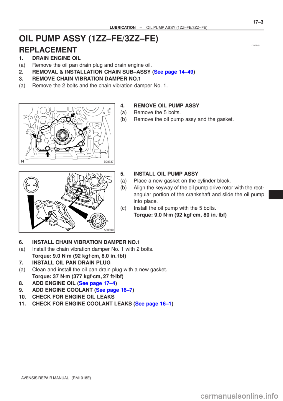
4.REMOVE OIL PUMP ASSY
(a)Remove the 5 bolts.
(b)Remove the oil pump assy and the gasket.
5.INSTALL OIL PUMP ASSY
(a)Place a new gasket on the cylinder block.
(b)Align the keyway of the oil pump drive rotor with the rect-angular portion of the crankshaft and slide the oil pump
into place.
(c)Install the oil pump with the 5 bolts. Torque: 9.0 N �m (92 kgf �cm, 80 in. �lbf)
6.INSTALL CHAIN VIBRATION DAMPER NO.1
(a)Install the chain vibration damper No. 1 with 2 bolts. Torque: 9.0 N �m (92 kgf �cm,8.0 in. �lbf)
7.INSTALL OIL PAN DRAIN PLUG
(a)Clean and install the oil pan drain plug with a new gasket.
Torque: 37 N �m (377 kgf �cm,27 ft �lbf)
8.ADD ENGINE OIL (See page 17±4)
9.ADD ENGINE COOLANT (See page 16±7)
10. CHECK FOR ENGINE OIL LEAKS
11.CHECK FOR ENGINE COOLANT LEAKS (See page 16±1)
Page 1098 of 1690
D30080
41±30
±
MANUAL TRANSMISSION/TRANSAXLE MANUAL TRANSAXLE ASSY (1AZ±FE/1AZ±FSE)
AVENSIS REPAIR MANUAL (RM1018E)
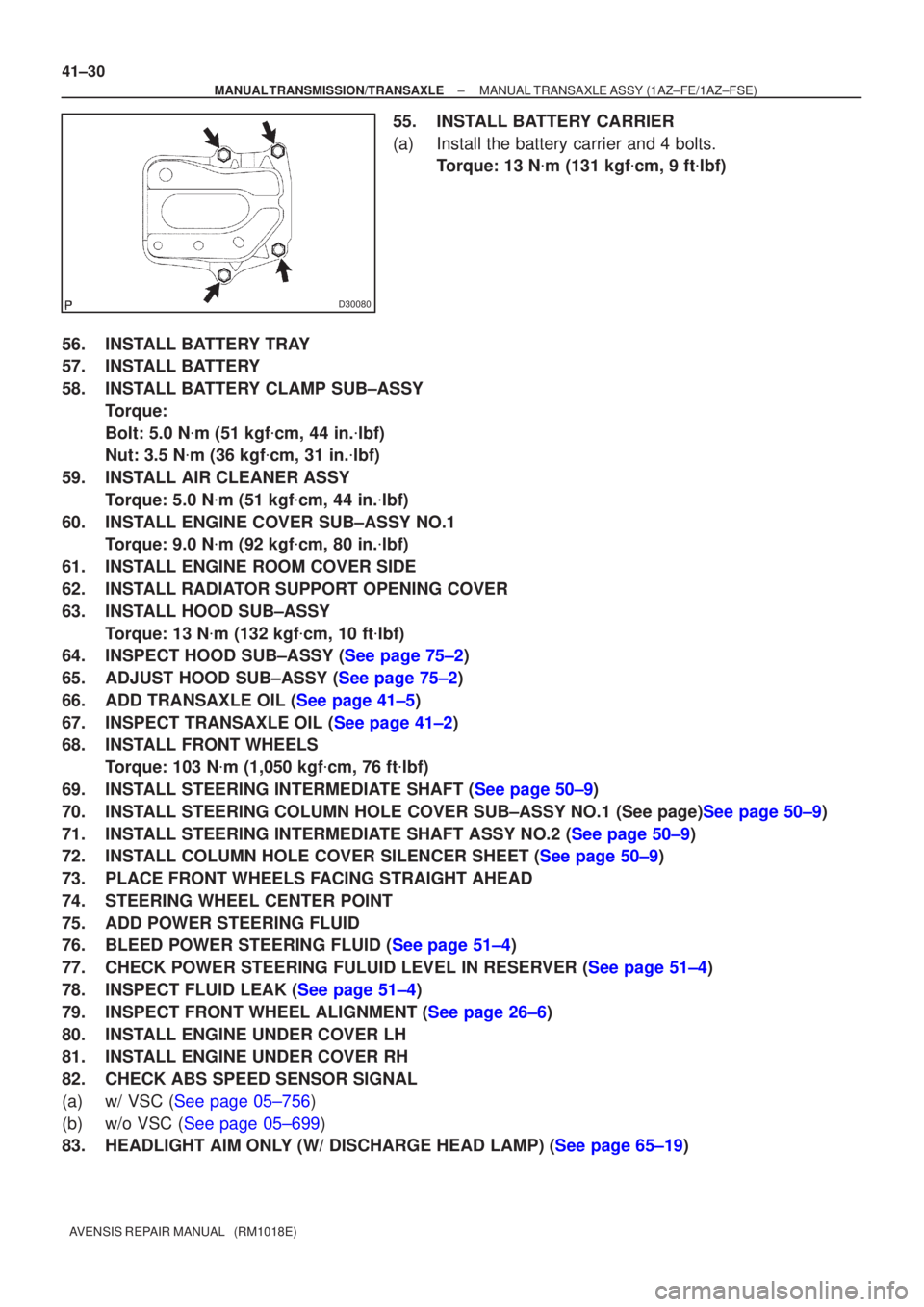
55. INSTALL BATTERY CARRIER
(a) Install the battery carrier and 4 bolts. Torque: 13 N �m (131 kgf �cm, 9 ft �lbf)
56. INSTALL BATTERY TRAY
57. INSTALL BATTERY
58. INSTALL BATTERY CLAMP SUB±ASSY Torque:
Bolt: 5.0 N �m (51 kgf �cm, 44 in. �lbf)
Nut: 3.5 N �m (36 kgf �cm, 31 in. �lbf)
59. INSTALL AIR CLEANER ASSY Torque: 5.0 N �m (51 kgf �cm, 44 in. �lbf)
60. INSTALL ENGINE COVER SUB±ASSY NO.1 Torque: 9.0 N �m (92 kgf �cm, 80 in. �lbf)
61. INSTALL ENGINE ROOM COVER SIDE
62. INSTALL RADIATOR SUPPORT OPENING COVER
63. INSTALL HOOD SUB±ASSY Torque: 13 N �m (132 kgf �cm, 10 ft �lbf)
64.INSPECT HOOD SUB±ASSY (See page 75±2)
65.ADJUST HOOD SUB±ASSY (See page 75±2)
66.ADD TRANSAXLE OIL (See page 41±5)
67.INSPECT TRANSAXLE OIL (See page 41±2)
68. INSTALL FRONT WHEELS
Torque: 103 N �m (1,050 kgf �cm, 76 ft �lbf)
69.INSTALL STEERING INTERMEDIATE SHAFT (See page 50±9)
70.INSTALL STEERING COLUMN HOLE COVER SUB±ASSY NO.1 (See page)See page 50±9)
71.INSTALL STEERING INTERMEDIATE SHAFT ASSY NO.2 (See page 50±9)
72.INSTALL COLUMN HOLE COVER SILENCER SHEET (See page 50±9)
73. PLACE FRONT WHEELS FACING STRAIGHT AHEAD
74. STEERING WHEEL CENTER POINT
75. ADD POWER STEERING FLUID
76.BLEED POWER STEERING FLUID (See page 51±4)
77.CHECK POWER STEERING FULUID LEVEL IN RESERVER (See page 51±4)
78.INSPECT FLUID LEAK (See page 51±4)
79.INSPECT FRONT WHEEL ALIGNMENT (See page 26±6)
80. INSTALL ENGINE UNDER COVER LH
81. INSTALL ENGINE UNDER COVER RH
82. CHECK ABS SPEED SENSOR SIGNAL
(a)w/ VSC (See page 05±756)
(b)w/o VSC (See page 05±699)
83.HEADLIGHT AIM ONLY (W/ DISCHARGE HEAD LAMP) (See page 65±19)
Page 1108 of 1690
41±40
±
MANUAL TRANSMISSION/TRANSAXLE MANUAL TRANSAXLE ASSY (1CD±FTV)
AVENSIS REPAIR MANUAL (RM1018E)
75. INSTALL HOOD SUB±ASSY Torque: 13 N �m (133 kgf �cm, 10 ft �lbf)
76.INSPECT HOOD SUB±ASSY (See page 75±2)
77.ADJUST HOOD SUB±ASSY (See page 75±2)
78.ADD TRANSAXLE OIL (See page 41±5)
79.INSPECT TRANSAXLE OIL (See page 41±2)
80. ADD POWER STEERING FLUID
81.BLEED POWER STEERING FLUID (See page 51±4)
82.CHECK POWER STEERING FULUID LEVEL IN RESERVER (See page 51±4)
83.INSPECT FLUID LEAK (See page 51±4)
84. INSTALL FRONT WHEELS Torque: 103 N �m (1,050 kgf �cm, 76 ft �lbf)
85.INSPECT FRONT WHEEL ALIGNMENT (See page 26±6)
86. INSTALL ENGINE UNDER COVER RH
87. INSTALL ENGINE UNDER COVER LH
88. CHECK ABS SPEED SENSOR SIGNAL
(a)w/ VSC (See page 05±756)
(b)w/o VSC (See page 05±699)
89.HEADLIGHT AIM ONLY (W/ DISCHARGE HEAD LAMP) (See page 65±19)
Page 1138 of 1690
510DE±02
F40449
R11229
Normal
Abnormal
R00427
51±4
± POWER STEERINGPOWER STEERING SYSTEM
AVENSIS REPAIR MANUAL (RM1018E)
ON±VEHICLE INSPECTION
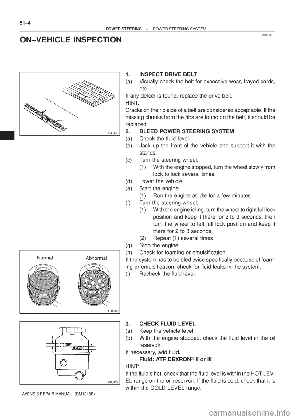
1. INSPECT DRIVE BELT
(a) Visually check the belt for excessive wear, frayed cords,
etc.
If any defect is found, replace the drive belt.
HINT:
Cracks on the rib side of a belt are considered acceptable. If the
missing chunks from the ribs are found on the belt, it should be
replaced.
2. BLEED POWER STEERING SYSTEM
(a) Check the fluid level.
(b) Jack up the front of the vehicle and support it with the
stands.
(c) Turn the steering wheel.
(1) With the engine stopped, turn the wheel slowly from
lock to lock several times.
(d) Lower the vehicle.
(e) Start the engine.
(1) Run the engine at idle for a few minutes.
(f) Turn the steering wheel.
(1) With the engine idling, turn the wheel to right full lock
position and keep it there for 2 to 3 seconds, then
turn the wheel to left full lock position and keep it
there for 2 to 3 seconds.
(2) Repeat (1) several times.
(g) Stop the engine.
(h) Check for foaming or emulsification.
If the system has to be bled twice specifically because of foam-
ing or emulsification, check for fluid leaks in the system.
(i) Recheck the fluid level.
3. CHECK FLUID LEVEL
(a) Keep the vehicle level.
(b) With the engine stopped, check the fluid level in the oil
reservoir.
If necessary, add fluid.
Fluid: ATF DEXRON� II or III
HINT:
If the fluidis hot, check that the fluid level is within the HOT LEV-
EL range on the oil reservoir. If the fluid is cold, check that it is
within the COLD LEVEL range.
Page 1139 of 1690
R11229
NormalAbnormal
R11786Engine Idling Engine Stopped5 mm (0.20 in.)
or less
±
POWER STEERING POWER STEERING SYSTEM
51±5
AVENSIS REPAIR MANUAL (RM1018E)
(c) Start the engine and run it at idle.
(d) Turn the steering wheel from lock to lock several times to
boost fluid temperature.
Fluid temperature: 80 �C (176 �F)
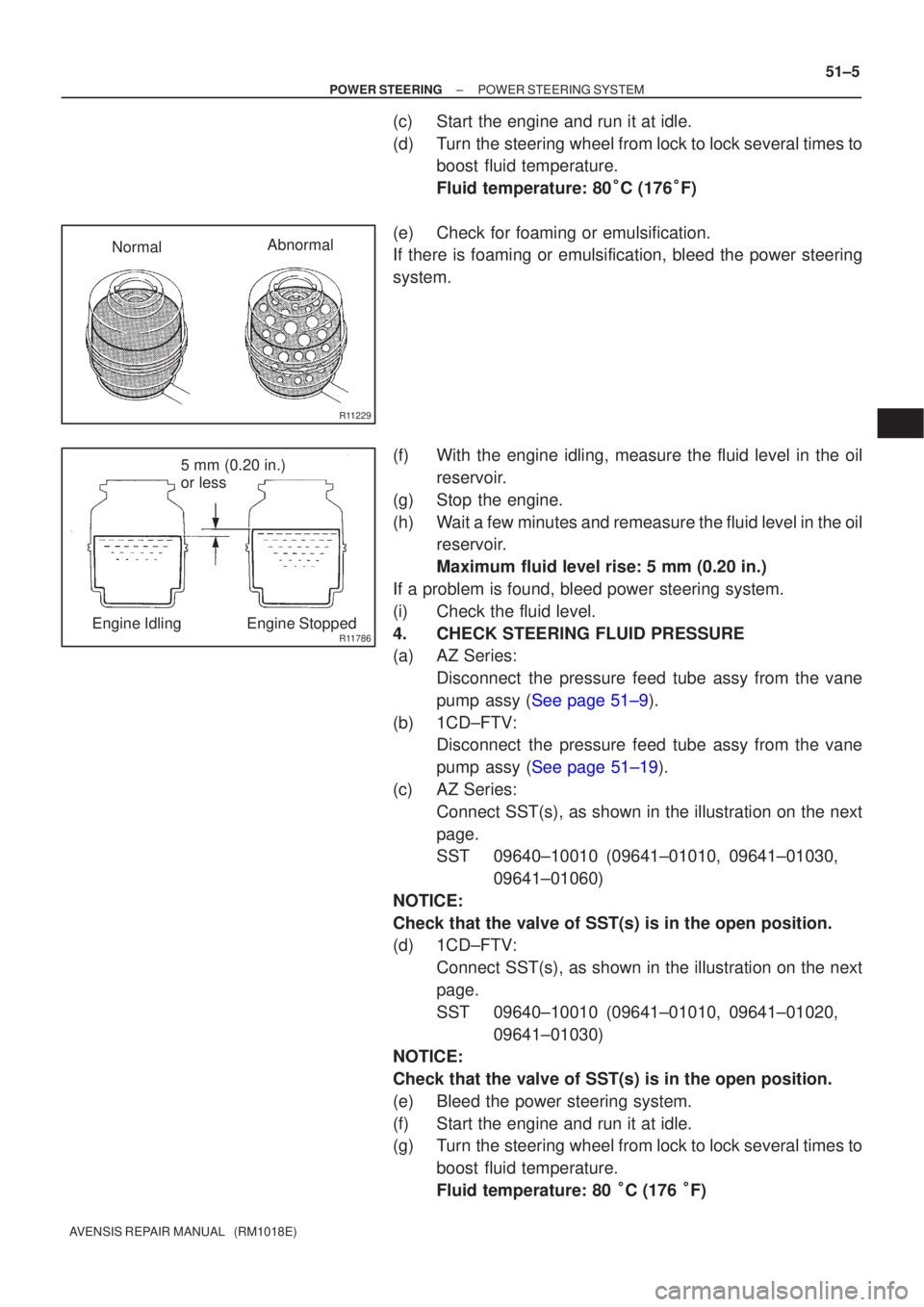
(e) Check for foaming or emulsification.
If there is foaming or emulsification, bleed the power steering
system.
(f) With the engine idling, measure the fluid level in the oil reservoir.
(g) Stop the engine.
(h) Wait a few minutes and remeasure the fluid level in the oil reservoir.
Maximum fluid level rise: 5 mm (0.20 in.)
If a problem is found, bleed power steering system.
(i) Check the fluid level.
4. CHECK STEERING FLUID PRESSURE
(a) AZ Series: Disconnect the pressure feed tube assy from the vane
pump assy (See page 51±9).
(b) 1CD±FTV: Disconnect the pressure feed tube assy from the vane
pump assy (See page 51±19).
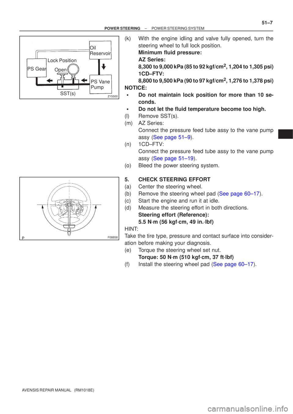
(c) AZ Series: Connect SST(s), as shown in the illustration on the next
page.
SST 09640±10010 (09641±01010, 09641±01030, 09641±01060)
NOTICE:
Check that the valve of SST(s) is in the open position.
(d) 1CD±FTV: Connect SST(s), as shown in the illustration on the next
page.
SST 09640±10010 (09641±01010, 09641±01020, 09641±01030)
NOTICE:
Check that the valve of SST(s) is in the open position.
(e) Bleed the power steering system.
(f) Start the engine and run it at idle.
(g) Turn the steering wheel from lock to lock several times to
boost fluid temperature.
Fluid temperature: 80 �C (176 �F)
Page 1141 of 1690
Z15500
Oil
ReservoirPS Vane
Pump
PS Gear
SST(s)
Open
Lock Position
F08858
±
POWER STEERING POWER STEERING SYSTEM
51±7
AVENSIS REPAIR MANUAL (RM1018E)
(k) With the engine idling and valve fully opened, turn the
steering wheel to full lock position.
Minimum fluid pressure:
AZ Series:
8,300 to 9,000 kPa (85 to 92 kgf/cm
2, 1,204 to 1,305 psi)
1CD±FTV:
8,800 to 9,500 kPa (90 to 97 kgf/cm
2, 1,276 to 1,378 psi)
NOTICE:
�Do not maintain lock position for more than 10 se-
conds.
�Do not let the fluid temperature become too high.
(l) Remove SST(s).
(m) AZ Series:
Connect the pressure feed tube assy to the vane pump
assy (See page 51±9).
(n) 1CD±FTV:
Connect the pressure feed tube assy to the vane pump
assy (See page 51±19).
(o) Bleed the power steering system.
5. CHECK STEERING EFFORT
(a) Center the steering wheel.
(b)Remove the steering wheel pad (See page 60±17).
(c) Start the engine and run it at idle.
(d) Measure the steering effort in both directions. Steering effort (Reference):
5.5 N´m (56 kgf´cm, 49 in.´lbf)
HINT:
Take the tire type, pressure and contact surface into consider-
ation before making your diagnosis.
(e) Torque the steering wheel set nut. Torque: 50 N´m (510 kgf´cm, 37 ft´lbf)
(f)Install the steering wheel pad (See page 60±17).
Page 1153 of 1690
������
������D30705
LHD:
A
B
RHD:
Matchmarks
Matchmarks
A
B
±
POWER STEERING RACK & PINION POWER STEERING GEAR ASSY
51±45
AVENSIS REPAIR MANUAL (RM1018E)
50. INSTALL HEIGHT CONTROL SENSOR SUB±ASSY FR RH (W/ DISCHARGE HEAD LAMP)
(See page 65±28)
51.INSTALL TIE ROD END SUB±ASSY LH (See page 30±6)
52. INSTALL TIE ROD END SUB±ASSY RH
HINT:
Perform the same procedure on the other side.
53. INSTALL FRONT WHEELS
Torque: 103 N �m (1,050 kgf �cm, 76 ft �lbf)
54. INSTALL STEERING COLUMN HOLE COVER SUB±ASSY NO.1
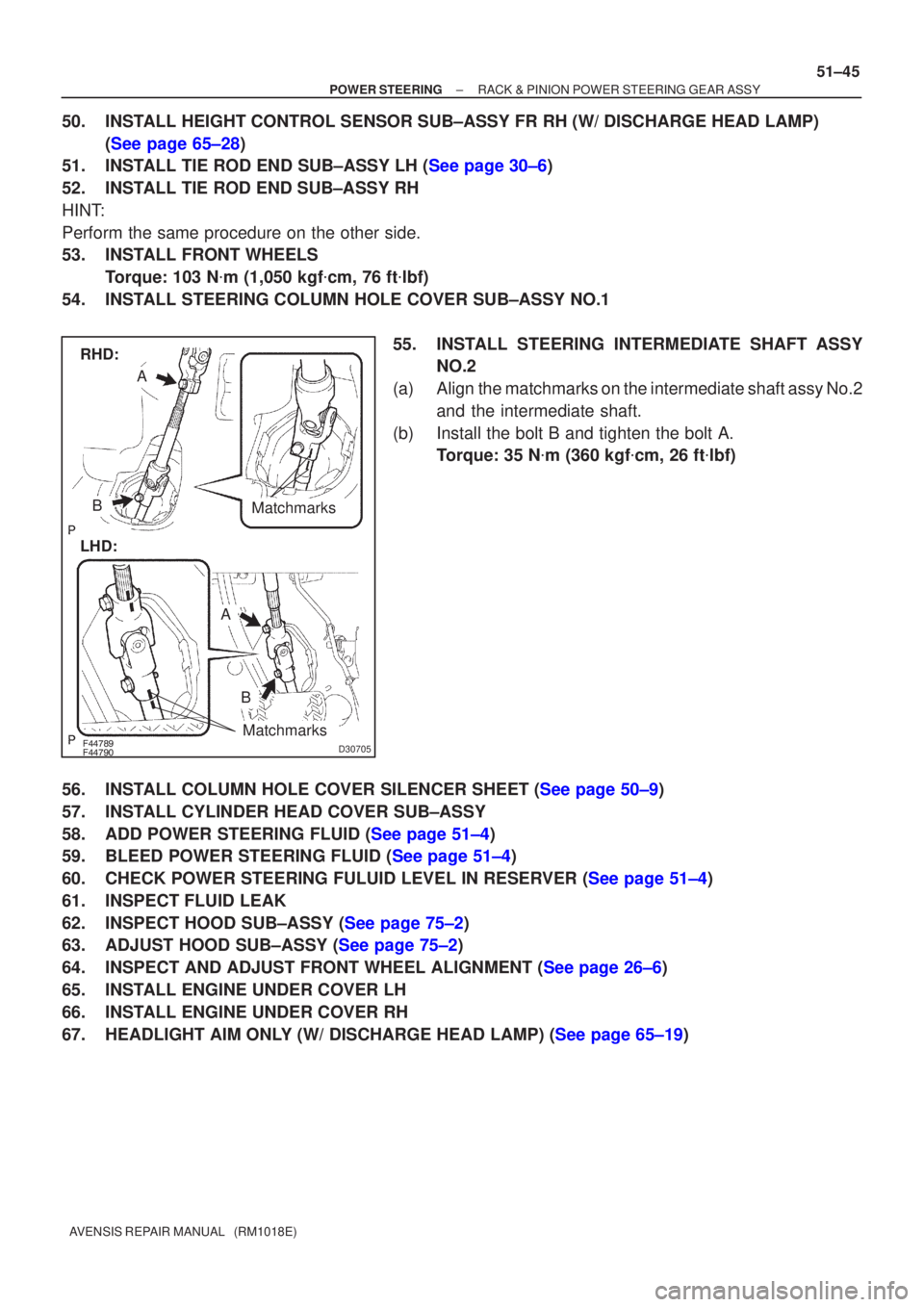
55. INSTALL STEERING INTERMEDIATE SHAFT ASSYNO.2
(a) Align the matchmarks on the intermediate shaft assy No.2 and the intermediate shaft.
(b) Install the bolt B and tighten the bolt A. Torque: 35 N �m (360 kgf �cm, 26 ft �lbf)
56.INSTALL COLUMN HOLE COVER SILENCER SHEET (See page 50±9)
57. INSTALL CYLINDER HEAD COVER SUB±ASSY
58.ADD POWER STEERING FLUID (See page 51±4)
59.BLEED POWER STEERING FLUID (See page 51±4)
60.CHECK POWER STEERING FULUID LEVEL IN RESERVER (See page 51±4)
61. INSPECT FLUID LEAK
62.INSPECT HOOD SUB±ASSY (See page 75±2)
63.ADJUST HOOD SUB±ASSY (See page 75±2)
64.INSPECT AND ADJUST FRONT WHEEL ALIGNMENT (See page 26±6)
65. INSTALL ENGINE UNDER COVER LH
66. INSTALL ENGINE UNDER COVER RH
67.HEADLIGHT AIM ONLY (W/ DISCHARGE HEAD LAMP) (See page 65±19)
Page 1179 of 1690
±
POWER STEERING VANE PUMP ASSY (AZ Series)
51±17
AVENSIS REPAIR MANUAL (RM1018E)
37. CONNECT OIL RESERVOIR TO PUMP HOSE NO.1
(a) Connect the oil reservoir to pump hose No.1 with the clip.
NOTICE:
Take care not to spill fluid on the V belt.
38. INSTALL FAN AND GENERATOR V BELT
1AZ±FE: (See page 14±105)
1AZ±FSE: (See page 14±185)
39. INSTALL ENGINE UNDER COVER RH
40. INSTALL FRONT WHEEL RH Torque: 103 N �m (1,050 kgf �cm, 76 ft �lbf)
41.ADD POWER STEERING FLUID (See page 51±4)
42.BLEED POWER STEERING FLUID (See page 51±4)
43.CHECK POWER STEERING FULUID LEVEL IN RESERVER (See page 51±4)
44. INSPECT FLUID LEAK