Page 86 of 1690
F40024
A
B
G23166
32±60
±
BRAKE SPEED SENSOR FRONT LH
AVENSIS REPAIR MANUAL (RM1018E)
(b)Install the sensor harness clamp with the 2 bolts ºAº and ºBº to the body and shock absorber.
Torque:
Bolt A: 8.0 N �m (82 kgf �cm, 71 in. �lbf)
Bolt B: 29 N �m (296 kgf �cm, 21 ft �lbf)
NOTICE:
Do not twist the sensor wire when installing the sensor.
(c)Connect the speed sensor connector.
(d)Connect the resin clip and speed sensor wire harness to the body and clamp.
5.INSTALL FRONT FENDER LINER LH
6.INSTALL FRONT WHEEL Torque: 103 N �m (1,050 kgf �cm, 76 ft �lbf)
7.CHECK ABS SPEED SENSOR SIGNAL (See page 05±699)
Page 123 of 1690
4206H±01
D26321
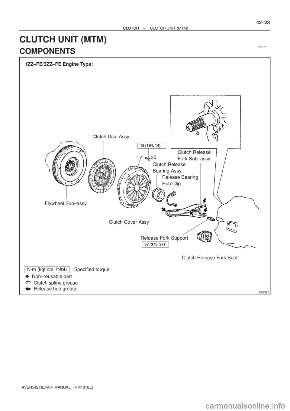
1ZZ±FE/3ZZ±FE Engine Type:
Flywheel Sub±assyClutch Disc Assy
Release hub grease
N�m (kgf�cm, ft�lbf) : Specified torque
�Non±reusable part
Clutch spline greasex6
Clutch Release
Bearing Assy
Release Bearing
Hub ClipClutch Release
Fork Sub±assy
Clutch Cover Assy
Clutch Release Fork Boot Release Fork Support
37 (375, 27)
19 (194, 14)
± CLUTCHCLUTCH UNIT (MTM)
42±23
AVENSIS REPAIR MANUAL (RM1018E)
CLUTCH UNIT (MTM)
COMPONENTS
Page 124 of 1690
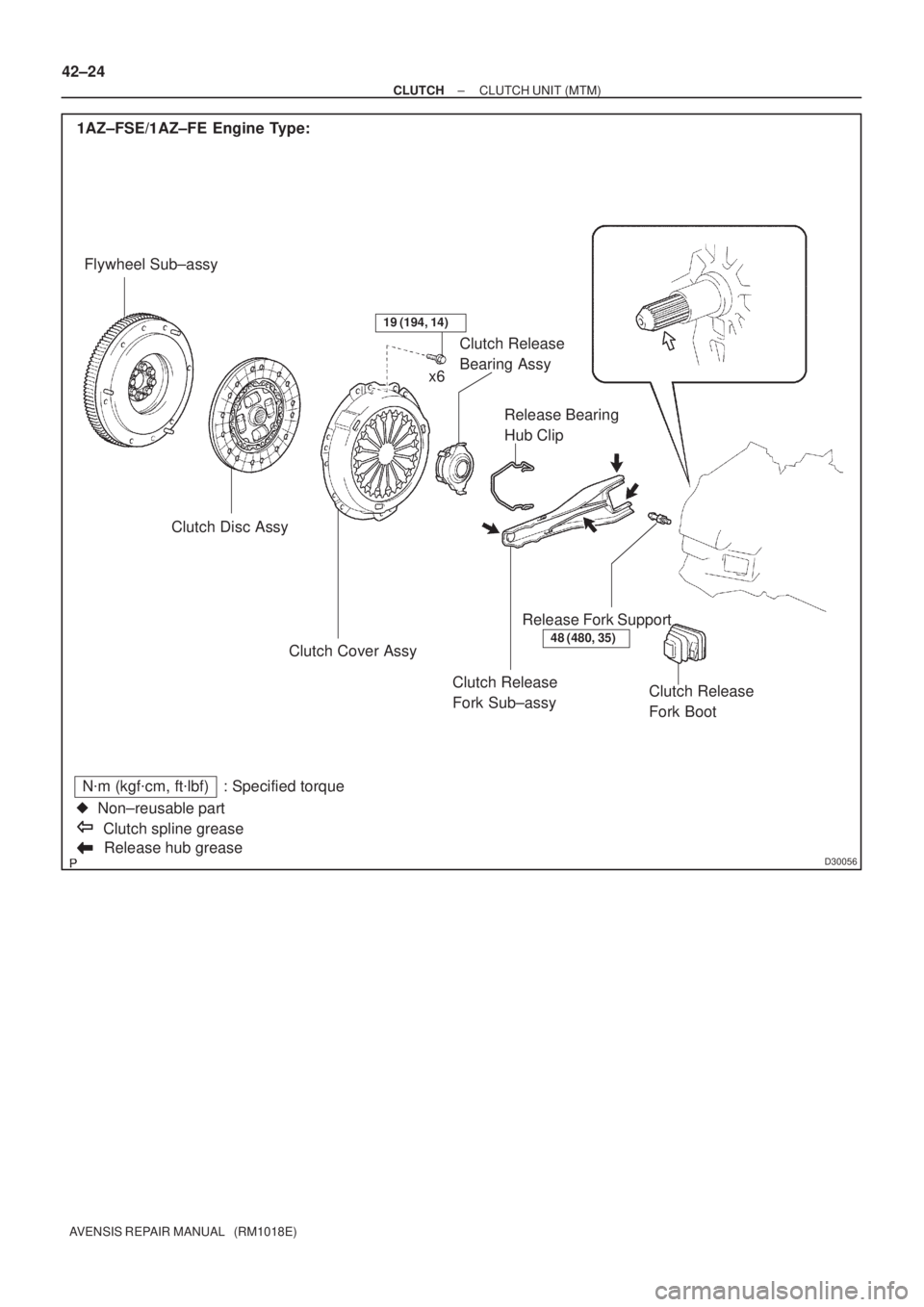
D30056Release hub grease
N�m (kgf�cm, ft�lbf) : Specified torque
�Non±reusable part
Clutch spline grease 1AZ±FSE/1AZ±FE Engine Type:
Flywheel Sub±assy
Clutch Disc Assy
Clutch Release
Fork Sub±assy Clutch Cover AssyRelease Bearing
Hub Clip Clutch Release
Bearing Assy
Release Fork Support
Clutch Release
Fork Boot
48 (480, 35)
19 (194, 14)
x6 42±24
± CLUTCHCLUTCH UNIT (MTM)
AVENSIS REPAIR MANUAL (RM1018E)
Page 125 of 1690
D30057
1CD±FTV Engine Type:
Flywheel Sub±assyClutch Disc Assy
Clutch Release Fork Sub±assy Clutch Cover Assy
Release Bearing
Hub Clip Clutch Release
Bearing Assy
Release Fork Support
Clutch Release
Fork Boot
37 (375, 27)
19 (194, 14)
x6
Release hub grease
N�m (kgf�cm, ft�lbf) : Specified torque
�Non±reusable part
Clutch spline grease
± CLUTCHCLUTCH UNIT (MTM)
42±25
AVENSIS REPAIR MANUAL (RM1018E)
Page 128 of 1690

D26323
SST(s)
Matchmarks 7
1 (Temporally), 4
3
6
2.58
D00205
SST(s)
42±28
± CLUTCHCLUTCH UNIT (MTM)
AVENSIS REPAIR MANUAL (RM1018E)")
Q01060
D30059
1CD±FTV Engine Type: Others:
Flywheel Side
SST(s)
D26323
SST(s)
Matchmarks 7
1 (Temporally), 4
3
6
2.58
D00205
SST(s)
42±28
± CLUTCHCLUTCH UNIT (MTM)
AVENSIS REPAIR MANUAL (RM1018E)
12. INSPECT CLUTCH RELEASE BEARING ASSY
(a) Turn the release bearing by hand while applying force in
the axial direction.
HINT:
The bearing is permanently lubricated and requires no cleaning
or lubrication.
Replace the release bearing assy as necessary.
13. INSTALL CLUTCH DISC ASSY
(a) Insert SST(s) in the clutch disc assy, then insert them in
the flywheel sub±assy.
SST 09301±00220
NOTICE:
Take care not to insert the clutch disc assy in the wrong
direction.
14. INSTALL CLUTCH COVER ASSY
(a) Align matchmarks on the clutch cover assy and flywheel
sub±assy.
(b) Following the procedures shown in the illustration, tighten
the 6 bolts, in the order starting from the bolt located near
the knock pin on the top.
Torque: 19 N�m (195 kgf�cm, 14 ft�lbf)
HINT:
�Following the order in the illustration, tighten the bolts at
a time evenly.
�Move SST(s) up and down, right and left lightly, after
checking that the disc is in the center, and then tighten the
bolts.
15. INSPECT AND ADJUST CLUTCH COVER ASSY
(a) Using a dial indicator with roller instrument, check the dia-
phragm spring tip alignment.
Maximum non±alignment: 0.5 mm (0.020 in.)
If the alignment is not as specified, adjust the diaphragm spring
tip alignment using SST(s).
SST 09333±00013
Page 186 of 1690

16±49
AVENSIS REPAIR MANUAL (RM1018E)
41.SET NO. 1 CYLINDER TO TDC/COMPRESSION
SST09960±10010 (09962±01000, 09963±01000)
42.INSTALL TIMING BELT(See page 14±")
±
COOLING WATER PUMP ASSY(1CD±FTV)
16±49
AVENSIS REPAIR MANUAL (RM1018E)
41.SET NO. 1 CYLINDER TO TDC/COMPRESSION
SST09960±10010 (09962±01000, 09963±01000)
42.INSTALL TIMING BELT(See page 14±307)
43.CHECK VALVE TIMING(See page 14±307)
44.INSTALL TIMING CHAIN COVER PLATE(See page 14±307)
45.INSTALL TRANSVERSE ENGINE ENGINE MOUNTING BRACKET(See page 14±307)
46.INSTALL TIMING BELT GUIDE(See page 14±307)
47.INSTALL TIMING BELT NO.1 COVER(See page 14±307)
48.INSTALL TIMING BELT NO.2 COVER(See page 14±307)
49.INSTALL IDLER PULLEY SUB±ASSY(See page 11±69)
50.INSTALL CRANKSHAFT PULLEY(See page 14±307) SST 09213±54015 (90105±08076), 09330±00021
51.INSTALL ENGINE MOUNTING INSULATOR SUB±ASSY RH(See page 14±307)
52.INSTALL POWER STEERING IDLE PULLEY BRACKET (See page 14±286)
53.ADJUST V (COOLER COMPRESSOR TO CRANKSHAFT PULLEY) BELT NO.1 (See page 14±269)
54.INSTALL INJECTOR DRIVER(See page 11±69)
55. INSTALL FRONT WHEEL RH Torque: 103 N �m (1,050 kgf �cm, 76 ft �lbf)
56. INSTALL ENGINE COVER NO.1
Torque: 8.0 N �m (82 kgf �cm, 71 in. �lbf)
57.ADD ENGINE COOLANT(See page 16±44)
58.CHECK FOR ENGINE COOLANT LEAKS(See page 16±44)
59.CHECK FOR FUEL LEAKS(See page 11±60)
Page 197 of 1690
C68609
30±28
±
DRIVE SHAFT / PROPELLER SHAFT FRONT AXLE HUB SUB±ASSY LH
AVENSIS REPAIR MANUAL (RM1018E)
34. INSTALL FRONT AXLE HUB LH NUT
(a) While applying the brakes, install a new axle hub LH nut. Torque: 216 N �m (2,200 kgf �cm, 159 ft �lbf)
(b) Using a chisel and hammer, stake the axle hub LH nut.
35. INSTALL FRONT WHEEL Torque: 103 N �m (1,050 kgf �cm, 76 ft �lbf)
36.INSPECT AND ADJUST FRONT WHEEL ALIGNMENT (See page 26±6)
37. CHECK ABS SPEED SENSOR SIGNAL
(a)ABD WITH EBD SYSTEM (See page 05±699)
(b)ABD WITH EBD & BA & TRC & VSC SYSTEM ( See page 05±756)
Page 198 of 1690
30092±02
D27405SST
Hold
Turn
D27401
Hold
Turn
Nut
Washer
±
DRIVE SHAFT / PROPELLER SHAFT FRONT AXLE LH HUB BOLT
30±29
AVENSIS REPAIR MANUAL (RM1018E)
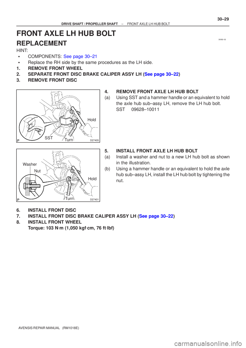
FRONT AXLE LH HUB BOLT
REPLACEMENT
HINT:
�COMPONENTS: See page 30±21
�Replace the RH side by the same procedures as the LH side.
1. REMOVE FRONT WHEEL
2.SEPARATE FRONT DISC BRAKE CALIPER ASSY LH (See page 30±22)
3. REMOVE FRONT DISC
4. REMOVE FRONT AXLE LH HUB BOLT
(a) Using SST and a hammer handle or an equivalent to holdthe axle hub sub±assy LH, remove the LH hub bolt.
SST 09628±10011
5. INSTALL FRONT AXLE LH HUB BOLT
(a) Install a washer and nut to a new LH hub bolt as shown in the illustration.
(b) Using a hammer handle or an equivalent to hold the axle hub sub±assy LH, install the LH hub bolt by tightening the
nut.
6. INSTALL FRONT DISC
7.INSTALL FRONT DISC BRAKE CALIPER ASSY LH (See page 30±22)
8. INSTALL FRONT WHEEL Torque: 103 N �m (1,050 kgf �cm, 76 ft �lbf)

(b)Install the sensor harness clamp with the 2 bolts ºAº and ºBº to the body and shock absorber.
Torque:
B")


34. INSTALL FRONT AXLE HUB LH NUT
(a) While applying the brakes, install a new axle hub LH")