2002 NISSAN TERRANO glow
[x] Cancel search: glowPage 365 of 1767
DTC Confirmation Procedure ..................................191
Diagnostic Procedure ..............................................191
DTC 0707 P7×F/INJ TIMG FB.....................................192
Description ...............................................................192
CONSULT-II Reference Value in Data Monitor
Mode ........................................................................193
ECM Terminals and Reference Value .....................193
On Board Diagnosis Logic.......................................193
DTC Confirmation Procedure ..................................194
Wiring Diagram ........................................................195
Diagnostic Procedure ..............................................197
DTC 0802 ECM 10.......................................................200
Description ...............................................................200
On Board Diagnosis Logic.......................................200
DTC Confirmation Procedure ..................................200
Diagnostic Procedure ..............................................201
DTC 0804 ECM 11.......................................................202
Description ...............................................................202
On Board Diagnosis Logic.......................................202
DTC Confirmation Procedure ..................................202
Diagnostic Procedure ..............................................203
DTC 0807 ECM 14.......................................................204
Description ...............................................................204
ECM Terminals and Reference Value .....................204
On Board Diagnosis Logic.......................................204
DTC Confirmation Procedure ..................................204
Wiring Diagram ........................................................205
Diagnostic Procedure ..............................................206
DTC 0902 ECM RLY....................................................209
ECM Terminals and Reference Value .....................209
On Board Diagnosis Logic.......................................209
DTC Confirmation Procedure ..................................209
Wiring Diagram ........................................................210
Diagnostic Procedure .............................................. 211
DTC 0903 ECM 15.......................................................213
Description ...............................................................213
On Board Diagnosis Logic.......................................213
DTC Confirmation Procedure ..................................213
Diagnostic Procedure ..............................................214
DTC 0905 TURBO PRESSURE..................................215
Component Description ...........................................215
ECM Terminals and Reference Value .....................215
On Board Diagnosis Logic.......................................215
DTC Confirmation Procedure ..................................216
Wiring Diagram ........................................................217
Diagnostic Procedure ..............................................219
DTC 1003 EGR VOLUME CONT/V.............................222
Description ...............................................................222
CONSULT-II Reference Value in Data Monitor
Mode ........................................................................223
ECM Terminals and Reference Value .....................223
On Board Diagnosis Logic.......................................223DTC Confirmation Procedure ..................................224
Wiring Diagram ........................................................225
Diagnostic Procedure ..............................................227
DTC 1004 FUEL CUT SYSTEM1................................232
Description ...............................................................232
CONSULT-II Reference Value in Data Monitor
Mode ........................................................................233
ECM Terminals and Reference Value .....................233
On Board Diagnosis Logic.......................................233
DTC Confirmation Procedure ..................................234
Wiring Diagram ........................................................235
Diagnostic Procedure ..............................................237
GLOW CONTROL SYSTEM.......................................239
Description ...............................................................239
ECM Terminals and Reference Value .....................240
Wiring Diagram ........................................................241
Diagnostic Procedure ..............................................242
START SIGNAL...........................................................248
Wiring Diagram ........................................................248
Diagnostic Procedure ..............................................249
PARK/NEUTRAL POSITION (PNP) SWITCH.............251
Description ...............................................................251
CONSULT-II Reference Value in Data Monitor
Mode ........................................................................251
ECM Terminals and Reference Value .....................251
Wiring Diagram ........................................................252
Diagnostic Procedure ..............................................253
HEAT UP SWITCH......................................................258
Component Description ...........................................258
CONSULT-II Reference Value in Data Monitor
Mode ........................................................................258
ECM Terminals and Reference Value .....................258
Wiring Diagram ........................................................259
Diagnostic Procedure ..............................................260
SWIRL CONTROL VALVE CONTROL SOLENOID
VA LV E..........................................................................263
Description ...............................................................263
CONSULT-II Reference Value in Data Monitor
Mode ........................................................................264
ECM Terminals and Reference Value .....................264
Wiring Diagram ........................................................265
Diagnostic Procedure ..............................................266
INTAKE AIR CONTROL VALVE CONTROL
SOLENOID VALVE......................................................273
Description ...............................................................273
Operation .................................................................273
ECM Terminals and Reference Value .....................273
Wiring Diagram ........................................................274
Diagnostic Procedure ..............................................275
VARIABLE NOZZLE TURBOCHARGER
CONTROL SOLENOID VALVE...................................281
Description ...............................................................281
CONTENTS(Cont'd)
EC-3
Page 366 of 1767
CONSULT-II Reference Value in Data Monitor
Mode ........................................................................281
ECM Terminals and Reference Value .....................282
Wiring Diagram ........................................................283
Diagnostic Procedure ..............................................284
AIR CONDITIONER CONTROL..................................289
Wiring Diagram ........................................................289
MI (MIL) & DATA LINK CONNECTORS.....................291
Wiring Diagram ........................................................291
SERVICE DATA AND SPECIFICATIONS (SDS)........292
General Specifications .............................................292
Injection Pump Numbers .........................................292
Injection Nozzle .......................................................292
Engine Coolant Temperature Sensor ......................292
Crankshaft Position Sensor (TDC) ..........................292
Glow Plug ................................................................292
Accelerator Position Sensor ....................................292
EGR Volume Control Valve .....................................292
TD27Ti
TROUBLE DIAGNOSIS - INDEX................................293
Alphabetical & Numerical Index for DTC ................293
PRECAUTIONS AND PREPARATION........................295
Special Service Tools ..............................................295
Engine Fuel & Emission Control System ................297
Precautions ..............................................................298
ENGINE AND EMISSION CONTROL OVERALL
SYSTEM.......................................................................300
Engine Control Component Parts Location .............300
Circuit Diagram ........................................................302
System Diagram ......................................................303
Vacuum Hose Drawing ............................................304
System Chart ...........................................................305
ENGINE AND EMISSION BASIC CONTROL
SYSTEM DESCRIPTION.............................................306
Fuel Injection System ..............................................306
Fuel Injection Timing System ..................................309
Air Conditioning Cut Control .................................... 311
Fuel Cut Control (at high engine speed) ................. 311
Glow Control ............................................................ 311
CRANKCASE VENTILATION SYSTEM......................312
Description ...............................................................312
Blow-by Control Valve .............................................312
Ventilation Hose .......................................................312
INJECTION NOZZLE...................................................313
Removal and Installation .........................................313
Disassembly (No.2-4nozzle) ...............................313
Inspection (No.2-4nozzle) ...................................314
Cleaning (No.2-4nozzle) .....................................314
Assembly (No.2-4nozzle) ....................................315
Test and Adjustment ................................................316
ELECTRONIC FUEL INJECTION PUMP....................318Removal ...................................................................318
Installation ................................................................319
Disassembly and Assembly .....................................320
ON BOARD DIAGNOSTIC SYSTEM
DESCRIPTION.............................................................321
DTC and MI Detection Logic ...................................321
Diagnostic Trouble Code (DTC) ..............................321
Malfunction Indicator (MI) ........................................322
CONSULT-II .............................................................327
TROUBLE DIAGNOSES.............................................334
Introduction ..............................................................334
Diagnostic Worksheet ..............................................335
Work Flow ................................................................336
Description for Work Flow .......................................337
Basic Inspection.......................................................338
Symptom Matrix Chart .............................................340
CONSULT-II Reference Value in Data Monitor
Mode ........................................................................343
Major Sensor Reference Graph in Data Monitor
Mode ........................................................................345
ECM Terminals and Reference Value .....................346
TROUBLE DIAGNOSIS FOR POWER SUPPLY........352
Wiring Diagram ........................................................352
Diagnostic Procedure ..............................................353
DTC P0100 MASS AIR FLOW SEN...........................356
Component Description ...........................................356
On Board Diagnosis Logic.......................................356
DTC Confirmation Procedure ..................................356
Wiring Diagram ........................................................357
Diagnostic Procedure ..............................................359
Component Inspection .............................................360
DTC P0115 COOLANT TEMP SEN............................361
Component Description ...........................................361
On Board Diagnosis Logic.......................................361
DTC Confirmation Procedure ..................................361
Wiring Diagram ........................................................362
Diagnostic Procedure ..............................................363
Component Inspection .............................................364
DTC P0120 ACCEL POS SENSOR............................365
Component Description ...........................................365
On Board Diagnosis Logic.......................................365
DTC Confirmation Procedure A (For General
Plausibility) ...............................................................365
DTC Confirmation Procedure B (For Accelerator
Sticking) ...................................................................366
Wiring Diagram ........................................................367
Diagnostic Procedure ..............................................368
Component Inspection .............................................371
DTC P0180 FUEL TEMP SENSOR............................372
Component Description ...........................................372
On Board Diagnosis Logic.......................................372
DTC Confirmation Procedure ..................................372
CONTENTS(Cont'd)
EC-4
Page 367 of 1767
Wiring Diagram ........................................................373
Diagnostic Procedure ..............................................374
Component Inspection .............................................375
DTC P0215 FUEL CUT S/V 1.....................................376
Component Description ...........................................376
On Board Diagnosis Logic.......................................376
DTC Confirmation Procedure ..................................376
Wiring Diagram ........................................................377
Diagnostic Procedure ..............................................378
Component Inspection .............................................379
DTC P0216 INJ TIMING CONT/V, DTC P1246 F/
INJ TIMG F/B...............................................................380
Component Description ...........................................380
On Board Diagnosis Logic.......................................380
DTC P0216 Confirmation Procedure.......................380
DTC P1246 Confirmation Procedure.......................381
Wiring Diagram ........................................................382
Diagnostic Procedure ..............................................383
Component Inspection .............................................384
DTC P0335 CRANK POS SEN (TDC)........................385
Component Description ...........................................385
On Board Diagnosis Logic.......................................385
DTC Confirmation Procedure ..................................385
Wiring Diagram ........................................................386
Diagnostic Procedure ..............................................387
Component Inspection .............................................388
DTC P0380 GLOW RELAY, DTC P0381 GLOW
LAMP...........................................................................389
System Description ..................................................389
Component Description ...........................................390
On Board Diagnosis Logic.......................................390
DTC Confirmation Procedure ..................................390
Wiring Diagram ........................................................391
Diagnostic Procedure ..............................................393
System Operation Check.........................................395
Component Inspection .............................................396
DTC P0500 VEHICLE SPEED SEN............................397
Component Description ...........................................397
On Board Diagnosis Logic.......................................397
Overall Function Check ...........................................397
Wiring Diagram ........................................................398
Diagnostic Procedure ..............................................399
DTC P0571 BRAKE SW..............................................400
Component Description ...........................................400
On Board Diagnosis Logic.......................................400
DTC Confirmation Procedure ..................................400
Wiring Diagram ........................................................401
Diagnostic Procedure ..............................................402
Component Inspection .............................................403
DTC P0650 MI.............................................................404
Component Description ...........................................404
On Board Diagnosis Logic.......................................404DTC Confirmation Procedure ..................................404
Wiring Diagram ........................................................405
Diagnostic Procedure ..............................................406
DTC P1107 ECM 10....................................................407
Description ...............................................................407
On Board Diagnosis Logic.......................................407
DTC Confirmation Procedure ..................................407
Diagnostic Procedure ..............................................408
DTC P1206 F/INJ F/B 2..............................................409
Component Description ...........................................409
On Board Diagnosis Logic.......................................409
DTC Confirmation Procedure ..................................410
Wiring Diagram ........................................................ 411
Diagnostic Procedure ..............................................412
Component Inspection .............................................413
DTC P1207 CONT SLEEV POS SEN.........................414
Component Description ...........................................414
On Board Diagnosis Logic.......................................414
DTC Confirmation Procedure ..................................414
Wiring Diagram ........................................................415
Diagnostic Procedure ..............................................416
Component Inspection .............................................417
DTC P1217 OVER HEAT............................................418
Description ...............................................................418
On Board Diagnosis Logic.......................................418
Overall Function Check ...........................................419
Wiring Diagram ........................................................420
Diagnostic Procedure ..............................................421
Main 12 Causes of Overheating..............................425
Component Inspection .............................................426
DTC P1240 NEEDLE LIFT SEN, DTC P1242
NEEDLE LIFT SE (RPM).............................................427
Component Description ...........................................427
On Board Diagnosis Logic.......................................427
DTC Confirmation Procedure ..................................427
Wiring Diagram ........................................................428
Diagnostic Procedure ..............................................429
Component Inspection .............................................430
DTC P1404 EGR SOL/V A, DTC P1405 EGR SOL/
V B/P1407 (THROTTLE SOLENOID VALVE)............431
System Description ..................................................431
Component Description ...........................................431
On Board Diagnosis Logic.......................................432
DTC Confirmation Procedure ..................................432
Wiring Diagram ........................................................433
Diagnostic Procedure ..............................................436
Component Inspection .............................................439
DTC P1530 AIR CONDITIONER RLY.........................440
Component Description ...........................................440
On Board Diagnosis Logic.......................................440
DTC Confirmation Procedure ..................................440
Wiring Diagram ........................................................441
CONTENTS(Cont'd)
EC-5
Page 381 of 1767
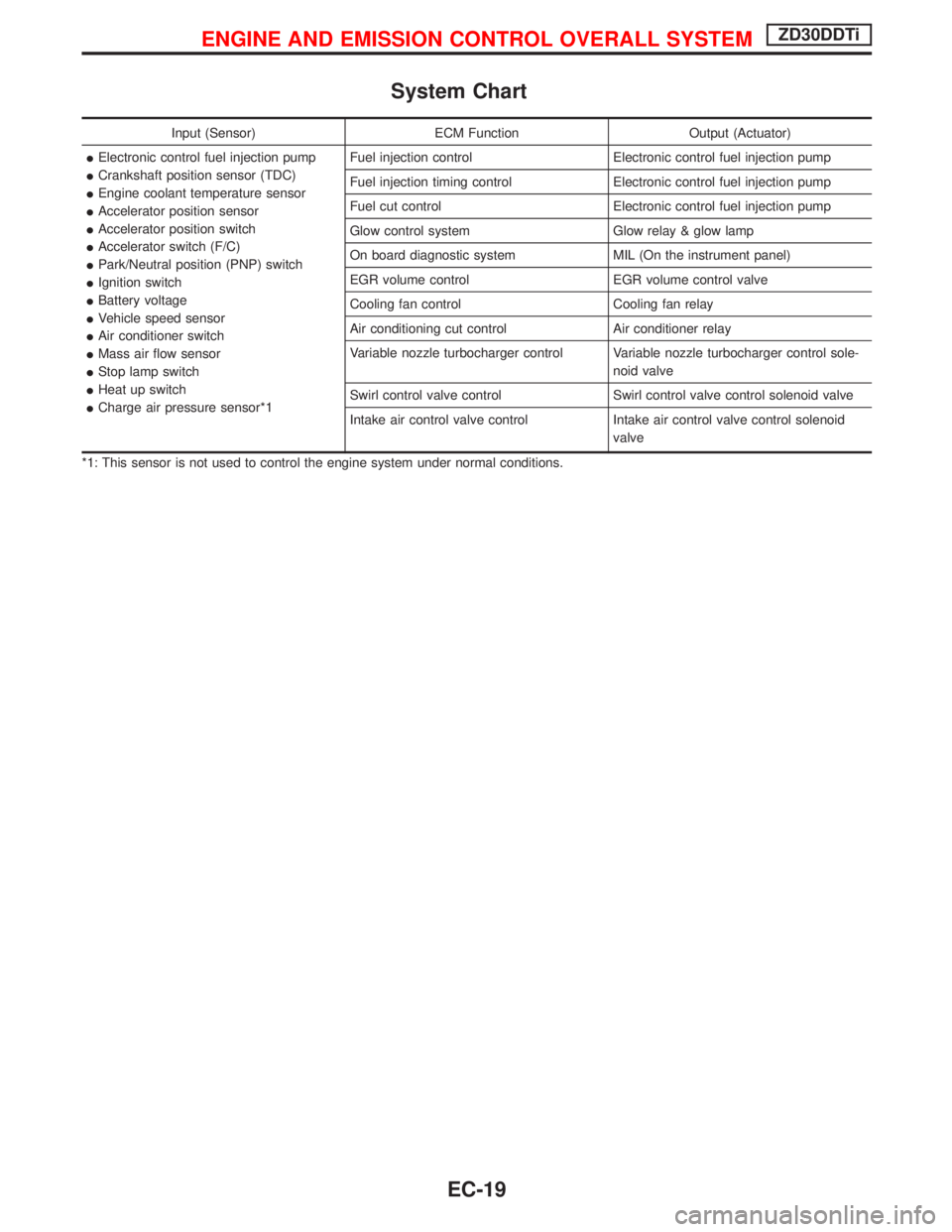
System Chart
Input (Sensor) ECM Function Output (Actuator)
IElectronic control fuel injection pump
ICrankshaft position sensor (TDC)
IEngine coolant temperature sensor
IAccelerator position sensor
IAccelerator position switch
IAccelerator switch (F/C)
IPark/Neutral position (PNP) switch
IIgnition switch
IBattery voltage
IVehicle speed sensor
IAir conditioner switch
IMass air flow sensor
IStop lamp switch
IHeat up switch
ICharge air pressure sensor*1Fuel injection control Electronic control fuel injection pump
Fuel injection timing control Electronic control fuel injection pump
Fuel cut control Electronic control fuel injection pump
Glow control system Glow relay & glow lamp
On board diagnostic system MIL (On the instrument panel)
EGR volume control EGR volume control valve
Cooling fan control Cooling fan relay
Air conditioning cut control Air conditioner relay
Variable nozzle turbocharger control Variable nozzle turbocharger control sole-
noid valve
Swirl control valve control Swirl control valve control solenoid valve
Intake air control valve control Intake air control valve control solenoid
valve
*1: This sensor is not used to control the engine system under normal conditions.
ENGINE AND EMISSION CONTROL OVERALL SYSTEMZD30DDTi
EC-19
Page 402 of 1767
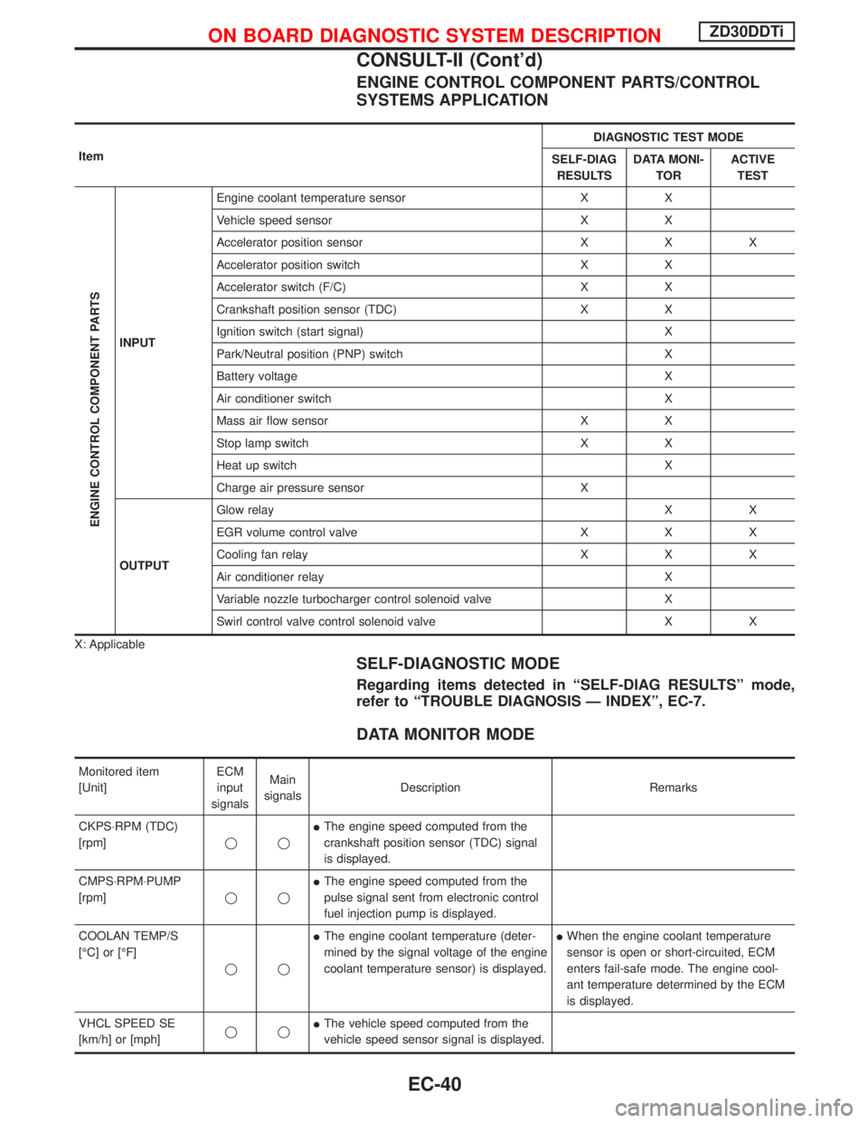
ENGINE CONTROL COMPONENT PARTS/CONTROL
SYSTEMS APPLICATION
ItemDIAGNOSTIC TEST MODE
SELF-DIAG
RESULTSDATA MONI-
TORACTIVE
TEST
ENGINE CONTROL COMPONENT PARTS
INPUTEngine coolant temperature sensor X X
Vehicle speed sensor X X
Accelerator position sensor X X X
Accelerator position switch X X
Accelerator switch (F/C) X X
Crankshaft position sensor (TDC) X X
Ignition switch (start signal) X
Park/Neutral position (PNP) switch X
Battery voltage X
Air conditioner switch X
Mass air flow sensor X X
Stop lamp switch X X
Heat up switch X
Charge air pressure sensor X
OUTPUTGlow relayXX
EGR volume control valve X X X
Cooling fan relay X X X
Air conditioner relay X
Variable nozzle turbocharger control solenoid valve X
Swirl control valve control solenoid valve X X
X: Applicable
SELF-DIAGNOSTIC MODE
Regarding items detected in ªSELF-DIAG RESULTSº mode,
refer to ªTROUBLE DIAGNOSIS Ð INDEXº, EC-7.
DATA MONITOR MODE
Monitored item
[Unit]ECM
input
signalsMain
signalsDescription Remarks
CKPS×RPM (TDC)
[rpm]qqIThe engine speed computed from the
crankshaft position sensor (TDC) signal
is displayed.
CMPS×RPM×PUMP
[rpm]qqIThe engine speed computed from the
pulse signal sent from electronic control
fuel injection pump is displayed.
COOLAN TEMP/S
[ÉC] or [ÉF]
qqIThe engine coolant temperature (deter-
mined by the signal voltage of the engine
coolant temperature sensor) is displayed.IWhen the engine coolant temperature
sensor is open or short-circuited, ECM
enters fail-safe mode. The engine cool-
ant temperature determined by the ECM
is displayed.
VHCL SPEED SE
[km/h] or [mph]qqIThe vehicle speed computed from the
vehicle speed sensor signal is displayed.
ON BOARD DIAGNOSTIC SYSTEM DESCRIPTIONZD30DDTi
CONSULT-II (Cont'd)
EC-40
Page 403 of 1767
![NISSAN TERRANO 2002 Service Repair Manual Monitored item
[Unit]ECM
input
signalsMain
signalsDescription Remarks
FUEL TEMP SEN
[ÉC] or [ÉF]qqIThe fuel temperature (sent from elec-
tronic control fuel injection pump) is dis-
played.
ACCEL POS](/manual-img/5/57393/w960_57393-402.png "NISSAN TERRANO 2002 Service Repair Manual Monitored item
[Unit]ECM
input
signalsMain
signalsDescription Remarks
FUEL TEMP SEN
[ÉC] or [ÉF]qqIThe fuel temperature (sent from elec-
tronic control fuel injection pump) is dis-
played.
ACCEL POS")
Monitored item
[Unit]ECM
input
signalsMain
signalsDescription Remarks
FUEL TEMP SEN
[ÉC] or [ÉF]qqIThe fuel temperature (sent from elec-
tronic control fuel injection pump) is dis-
played.
ACCEL POS SEN [V]
qqIThe accelerator position sensor signal
voltage is displayed.
FULL ACCEL SW
[ON/OFF]qqIIndicates [ON/OFF] condition from the
accelerator position switch signal.
ACCEL SW (FC)
[OPEN/CLOSE]qqIIndicates [OPEN/CLOSE] condition from
the accelerator switch (FC) signal.
OFF ACCEL SW
[ON/OFF]qqIIndicates [ON/OFF] condition from the
accelerator position switch signal.
SPILL/V [ÉCA]
qIThe control position of spill valve (sent
from electronic control fuel injection
pump) is displayed.
BATTERY VOLT [V]
qqIThe power supply voltage of ECM is dis-
played.
P/N POSI SW
[ON/OFF]qqIIndicates [ON/OFF] condition from the
park/neutral position switch signal.
START SIGNAL
[ON/OFF]qqIIndicates [ON/OFF] condition from the
starter signal.IAfter starting the engine, [OFF] is dis-
played regardless of the starter signal.
AIR COND SIG
[ON/OFF]qqIIndicates [ON/OFF] condition of the air
conditioner switch as determined by the
air conditioner signal.
BRAKE SW [ON/OFF]
qqIIndicates [ON/OFF] condition from the
stop lamp switch signal.
IGN SW
[ON/OFF]qqIIndicates [ON/OFF] condition from igni-
tion switch signal.
WARM UP SW
[ON/OFF]qIIndicates [ON/OFF] condition from the
heat up switch signal.
MAS AIR/FL SE [V]
qqIThe signal voltage of the mass air flow
sensor is displayed.IWhen the engine is stopped, a certain
value is indicated.
DECELER F/CUT
[ON/OFF]qIThe [ON/OFF] condition from decelera-
tion fuel cut signal (sent from electronic
control fuel injection pump) is displayed.
INJ TIMG C/V [%]
qIThe duty ratio of fuel injection timing
control valve (sent from electronic control
fuel injection pump) is displayed.
AIR COND RLY
[ON/OFF]qIIndicates the control condition of the air
conditioner relay (determined by ECM
according to the input signals).
GLOW RLY [ON/OFF]
qIThe glow relay control condition (deter-
mined by ECM according to the input
signal) is displayed.
COOLING FAN
[ON/OFF]
qIIndicates the control condition of the
cooling fans (determined by ECM
according to the input signal).
ION ... Operates.
OFF ... Stopped.
ON BOARD DIAGNOSTIC SYSTEM DESCRIPTIONZD30DDTi
CONSULT-II (Cont'd)
EC-41
Page 405 of 1767
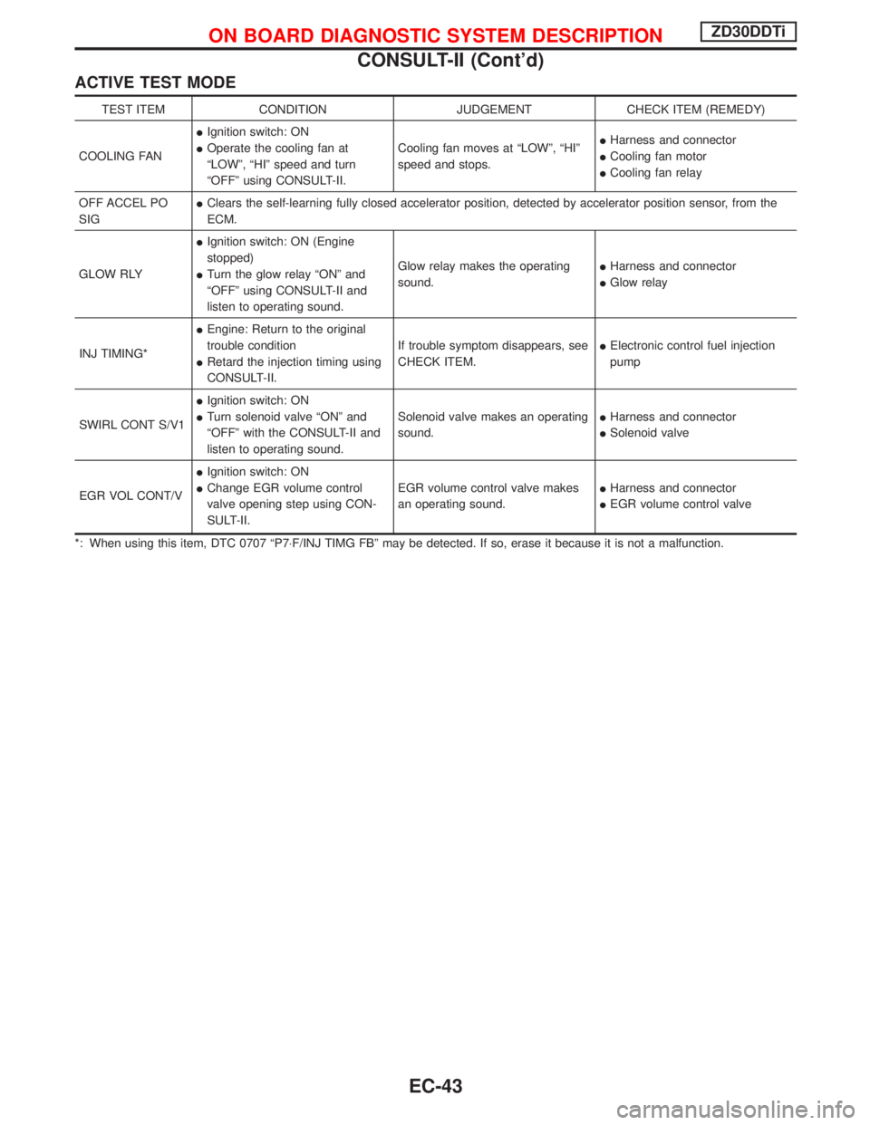
ACTIVE TEST MODE
TEST ITEM CONDITION JUDGEMENT CHECK ITEM (REMEDY)
COOLING FANIIgnition switch: ON
IOperate the cooling fan at
ªLOWº, ªHIº speed and turn
ªOFFº using CONSULT-II.Cooling fan moves at ªLOWº, ªHIº
speed and stops.IHarness and connector
ICooling fan motor
ICooling fan relay
OFF ACCEL PO
SIGIClears the self-learning fully closed accelerator position, detected by accelerator position sensor, from the
ECM.
GLOW RLYIIgnition switch: ON (Engine
stopped)
ITurn the glow relay ªONº and
ªOFFº using CONSULT-II and
listen to operating sound.Glow relay makes the operating
sound.IHarness and connector
IGlow relay
INJ TIMING*IEngine: Return to the original
trouble condition
IRetard the injection timing using
CONSULT-II.If trouble symptom disappears, see
CHECK ITEM.IElectronic control fuel injection
pump
SWIRL CONT S/V1IIgnition switch: ON
ITurn solenoid valve ªONº and
ªOFFº with the CONSULT-II and
listen to operating sound.Solenoid valve makes an operating
sound.IHarness and connector
ISolenoid valve
EGR VOL CONT/VIIgnition switch: ON
IChange EGR volume control
valve opening step using CON-
SULT-II.EGR volume control valve makes
an operating sound.IHarness and connector
IEGR volume control valve
*: When using this item, DTC 0707 ªP7×F/INJ TIMG FBº may be detected. If so, erase it because it is not a malfunction.
ON BOARD DIAGNOSTIC SYSTEM DESCRIPTIONZD30DDTi
CONSULT-II (Cont'd)
EC-43
Page 408 of 1767
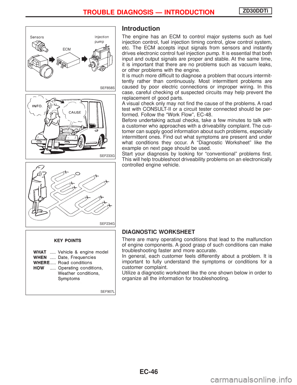
Introduction
The engine has an ECM to control major systems such as fuel
injection control, fuel injection timing control, glow control system,
etc. The ECM accepts input signals from sensors and instantly
drives electronic control fuel injection pump. It is essential that both
input and output signals are proper and stable. At the same time,
it is important that there are no problems such as vacuum leaks,
or other problems with the engine.
It is much more difficult to diagnose a problem that occurs intermit-
tently rather than continuously. Most intermittent problems are
caused by poor electric connections or improper wiring. In this
case, careful checking of suspected circuits may help prevent the
replacement of good parts.
A visual check only may not find the cause of the problems. A road
test with CONSULT-II or a circuit tester connected should be per-
formed. Follow the ªWork Flowº, EC-48.
Before undertaking actual checks, take a few minutes to talk with
a customer who approaches with a driveability complaint. The cus-
tomer can supply good information about such problems, especially
intermittent ones. Find out what symptoms are present and under
what conditions they occur. A ªDiagnostic Worksheetº like the
example on next page should be used.
Start your diagnosis by looking for ªconventionalº problems first.
This will help troubleshoot driveability problems on an electronically
controlled engine vehicle.
DIAGNOSTIC WORKSHEET
There are many operating conditions that lead to the malfunction
of engine components. A good grasp of such conditions can make
troubleshooting faster and more accurate.
In general, each customer feels differently about a problem. It is
important to fully understand the symptoms or conditions for a
customer complaint.
Utilize a diagnostic worksheet like the one shown below in order to
organize all the information for troubleshooting.
SEF858S
SEF233G
SEF234G
SEF907L
TROUBLE DIAGNOSIS Ð INTRODUCTIONZD30DDTi
EC-46