2002 NISSAN TERRANO g sensor
[x] Cancel search: g sensorPage 1516 of 1767
Removal
Transmission has to be removed as a unit together with transfer
box.
Remove transmission assembly as follows:
IDisconnect negative battery terminal.
IRemove shift levers of transmission and transfer.
IRemove front and rear propeller shafts. Ð Refer to PD section.
IInsert plug into rear oil seal after removing propeller shaft.
IRemove RPM-sensor from transmission upper side.
CAUTION:
Be careful not to damage spline, sleeve yoke and rear oil seal,
when removing propeller shaft.
IRemove torsion bar spring. Ð Refer to FA Section.
IRemove third crossmember (the one supporting front differen-
tial).
IRemove fifth crossmember (the one situated at the rear of
transfer).
ISupport transmission and transfer with a suitable transmission
jack.
WARNING:
Support transmission and transfer with suitable jacks, while
removing them.
IRemove fourth crossmember (the one supporting transmis-
sion).
IRemove clutch operating cylinder.
IRemove starter motor.
IRemove exhaust tube bracket from transmission.
IDisconnect electrical connectors.
IRemove transmission from engine.
REMOVAL AND INSTALLATIONFS5R30A
MT-7
Page 1518 of 1767
IRaise the unit with a hoist.
IPosition the transmission assembly on a portable jack and
secure it with a suitable tool.
Lift the assembly until the gearbox input shaft faces its hous-
ing.
Move the assembly towards the engine. The assembly must be
rotated slightly so that the starter motor housing clears the
projection on the companion floor. Insert input shaft into its
housing (slightly raising the rear of the transfer box may facili-
tate the introduction of the shaft into its housing).
ITighten the screws securing the gearbox to the engine.
:39-49N×m (4.0 - 5.0 kg-m, 29 - 36 ft-lb)
IConnect the electrical wiring. Secure with the respective clips.
IFit the RPM-sensor to the transmission upper side.
IFit the exhaust pipe support bracket to the transfer box.
:13-16N×m (1.3 - 1.6 kg-m,9-12ft-lb)
IFit the starter motor. Secure the earth wire to the starter motor
lower screw.
:31-41N×m (3.2 - 4.2 kg-m, 23 - 30 ft-lb)
IFit the clutch slave cylinder.
:30-40N×m (3.1 - 4.1 kg-m, 22 - 30 ft-lb)
IInstall fourth crossmember (Note the ªfrontº mark).
Crossmember fixing bolts to chassis:
:41-52N×m (4.2 - 5.3 kg-m, 30 - 38 ft-lb)
Crossmember fixing bolts to transmission:
:68-87N×m (6.9 - 8.9 kg-m, 50 - 64 ft-lb)
ITake away the portable jack holding boxes assembly.
IInstall fifth crossmember.
:59-78N×m (6.0 - 8.0 kg-m, 43 - 58 ft-lb)
IInstall third crossmember.
: Screws: 41 - 52 N×m (4.2 - 5.3 kg-m,
30 - 38 ft-lb)
Nuts: 68 - 87 N×m (6.9 - 8.9 kg-m,
50 - 64 ft-lb)
IInstall torsion bar springs. Ð Refer to FA section.
IInstall front and rear propeller shafts. Ð Refer to PD section.
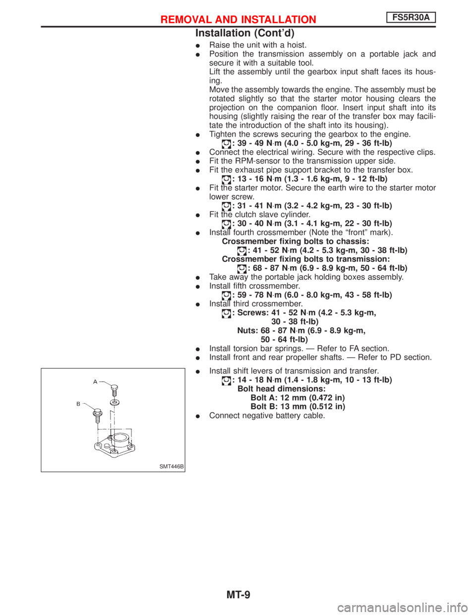
IInstall shift levers of transmission and transfer.
:14-18N×m (1.4 - 1.8 kg-m, 10 - 13 ft-lb)
Bolt head dimensions:
Bolt A: 12 mm (0.472 in)
Bolt B: 13 mm (0.512 in)
IConnect negative battery cable.
SMT446B
REMOVAL AND INSTALLATIONFS5R30A
Installation (Cont'd)
MT-9
Page 1612 of 1767
Removal
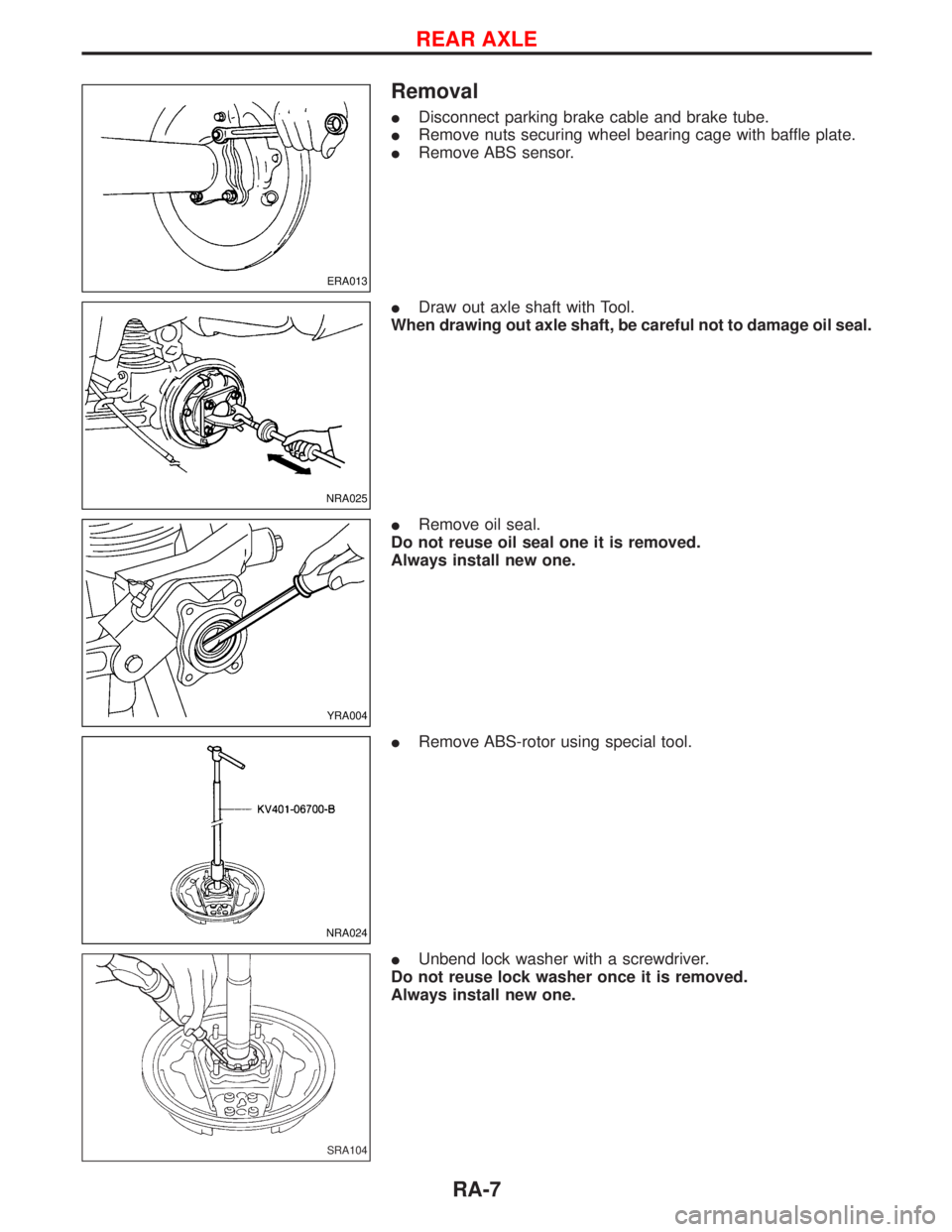
IDisconnect parking brake cable and brake tube.
IRemove nuts securing wheel bearing cage with baffle plate.
IRemove ABS sensor.
IDraw out axle shaft with Tool.
When drawing out axle shaft, be careful not to damage oil seal.
IRemove oil seal.
Do not reuse oil seal one it is removed.
Always install new one.
IRemove ABS-rotor using special tool.
IUnbend lock washer with a screwdriver.
Do not reuse lock washer once it is removed.
Always install new one.
ERA013
NRA025
YRA004
NRA024
SRA104
REAR AXLE
RA-7
Page 1615 of 1767
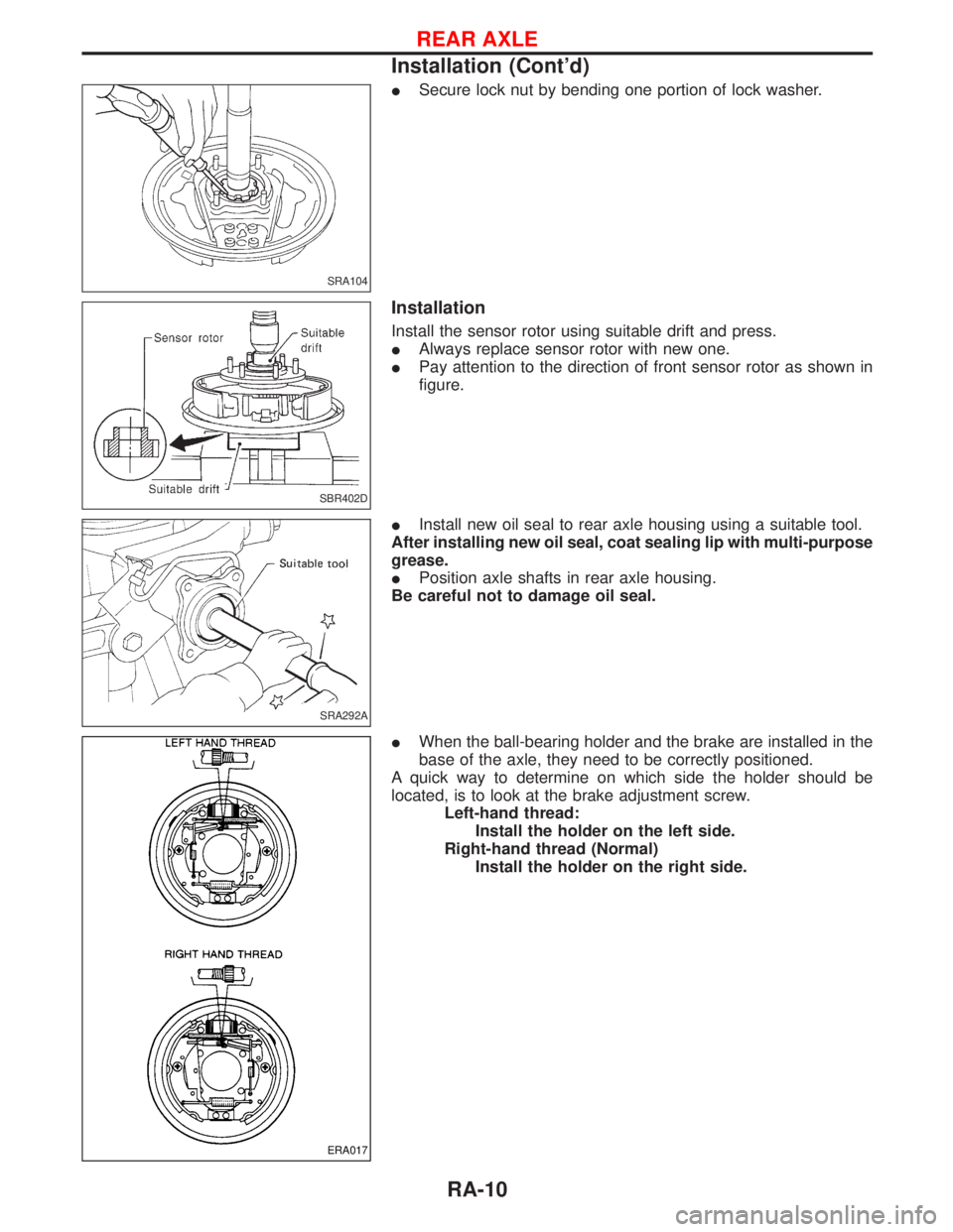
ISecure lock nut by bending one portion of lock washer.
Installation
Install the sensor rotor using suitable drift and press.
IAlways replace sensor rotor with new one.
IPay attention to the direction of front sensor rotor as shown in
figure.
IInstall new oil seal to rear axle housing using a suitable tool.
After installing new oil seal, coat sealing lip with multi-purpose
grease.
IPosition axle shafts in rear axle housing.
Be careful not to damage oil seal.
IWhen the ball-bearing holder and the brake are installed in the
base of the axle, they need to be correctly positioned.
A quick way to determine on which side the holder should be
located, is to look at the brake adjustment screw.
Left-hand thread:
Install the holder on the left side.
Right-hand thread (Normal)
Install the holder on the right side.
SRA104
SBR402D
SRA292A
ERA017
REAR AXLE
Installation (Cont'd)
RA-10
Page 1616 of 1767
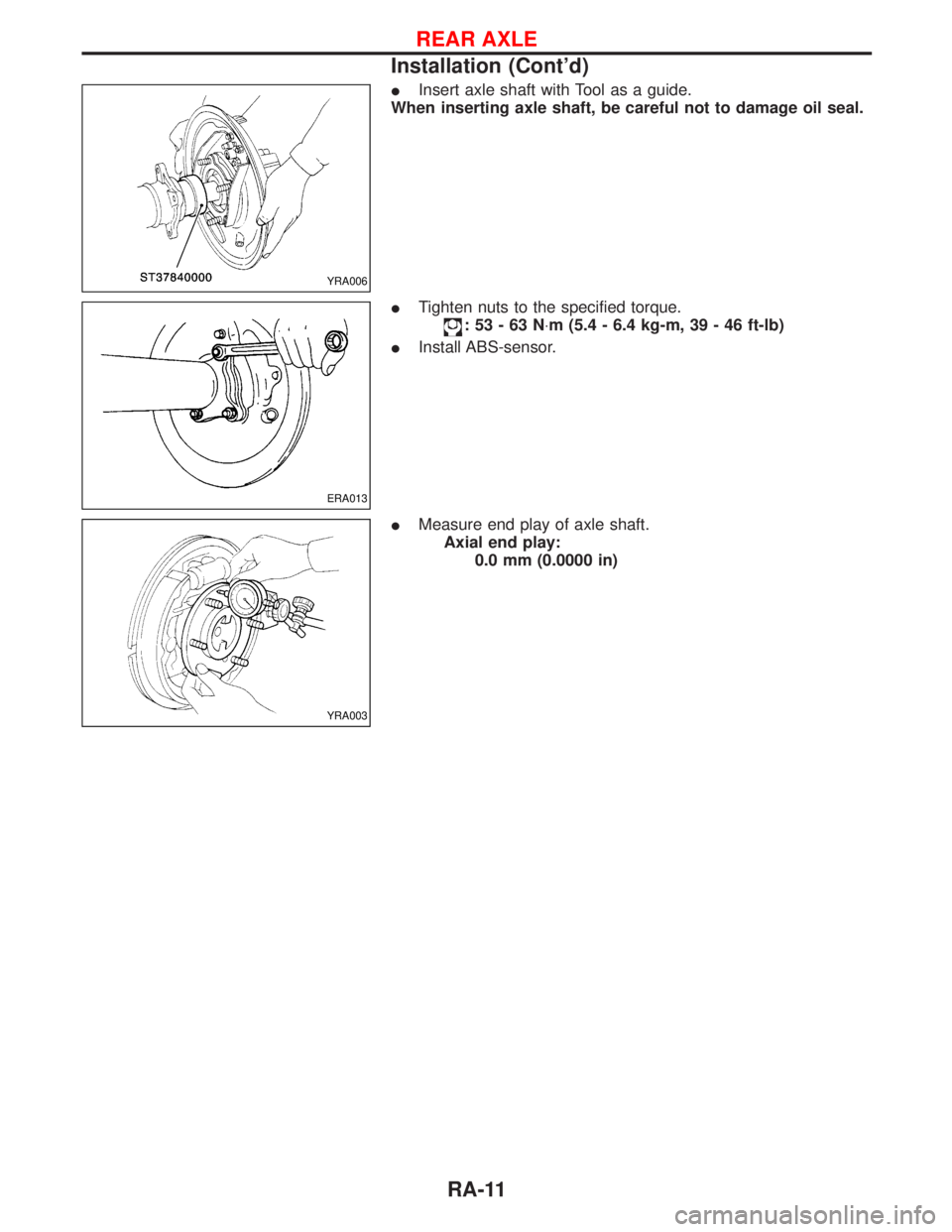
IInsert axle shaft with Tool as a guide.
When inserting axle shaft, be careful not to damage oil seal.
ITighten nuts to the specified torque.
:53-63N×m (5.4 - 6.4 kg-m, 39 - 46 ft-lb)
IInstall ABS-sensor.
IMeasure end play of axle shaft.
Axial end play:
0.0 mm (0.0000 in)
YRA006
ERA013
YRA003
REAR AXLE
Installation (Cont'd)
RA-11
Page 1622 of 1767
RESTRAINT SYSTEM
SECTION
RS
CONTENTS
SEAT BELTS...................................................................2
Precautions ..................................................................2
Front Seat Belt.............................................................4
SUPPLEMENTAL RESTRAINT SYSTEM (SRS)............6
Precautions ..................................................................6
Preparation ..................................................................7
SRS Configuration .......................................................8
Seat Belt Pre-tensioner with Load Limiter...................9
Built-in Type Side Air Bag............................................9
SRS Component Parts Location ...............................10
Maintenance Items ....................................................10
Diagnosis Sensor Unit ............................................... 11
Front Seat Belt Pre-tensioner ....................................12
Side Air Bag (Satellite) Sensor ..................................13
Driver Air Bag Module and Spiral Cable ...................14
Front Passenger Air Bag Module ..............................17Front Side Air Bag Module ........................................18
Disposal of Air Bag Module and Seat Belt Pre-
tensioner ....................................................................20
Trouble Diagnoses Introduction.................................26
How to Perform Trouble Diagnoses for Quick
and Accurate Repair ..................................................29
Schematic ..................................................................31
Wiring Diagram - SRS -.............................................32
SRS Operation Check ...............................................36
Trouble Diagnoses with CONSULT-II..................37
Trouble Diagnoses without CONSULT-II.............46
Trouble Diagnoses:²AIR BAG²Warning Lamp
Does Not Turn Off .....................................................54
Trouble Diagnoses:²AIR BAG²Warning Lamp
Does Not Turn On .....................................................56
Collision Diagnosis ....................................................57
Page 1623 of 1767
Precautions
SUPPLEMENTAL RESTRAINT SYSTEM (SRS) ªAIR BAGº AND ªSEAT BELT
PRE-TENSIONERº
The Supplemental Restraint System such as ªAIR BAGº and ªSEAT BELT PRE-TENSIONERº used along with
a seat belt, helps to reduce the risk or severity of injury to the driver and front passenger for certain types of
collision. The SRS composition which is available to NISSAN MODEL R20 is as follows (The composition
varies according to the destination and optional equipment.):
IFor a frontal collision
The Supplemental Restraint System consists of driver air bag module (located in the center of the steer-
ing wheel), front passenger air bag module (located on the instrument panel on passenger side), front seat
belt pre-tensioners, a diagnosis sensor unit, warning lamp, wiring harness and spiral cable.
IFor a side collision
The Supplemental Restraint System consists of front side air bag module (located in the outer side of front
seat), side air bag (satellite) sensor, diagnosis sensor unit (one of components of air bags for a frontal
collision), wiring harness, warning lamp (one of components of air bags for a frontal collision).
WARNING:
ITo avoid rendering the SRS inoperative, which could increase the risk of personal injury or death
in the event of a collision which would result in air bag inflation, all maintenance should be per-
formed by an authorized NISSAN dealer.
IImproper maintenance, including incorrect removal and installation of the SRS, can lead to per-
sonal injury caused by unintentional activation of the system.
IDo not use electrical test equipment on any circuit related to the SRS unless instructed to in this
Service Manual. Spiral cable and wiring harnesses covered with yellow insulation tape either just
before the harness connectors or for the complete harness are related to the SRS.
Precaution for Seat Belt Service
CAUTION:
IBefore removing the seat belt pre-tensioner assembly, turn the ignition switch off, disconnect both
battery cables and wait at least 3 minutes.
IDo not use electrical test equipment for seat belt pre-tensioner connector.
IAfter replacing or reinstalling seat belt pre-tensioner assembly, or reconnecting seat belt pre-ten-
sioner connector, check the system function. Refer to ªSRS Operation Checkº for details. (RS-36)
IDo not disassemble buckle or seat belt assembly.
IReplace anchor bolts if they are deformed or worn out.
INever oil tongue and buckle.
IIf any component of seat belt assembly is questionable, do not repair. Replace the whole seat belt
assembly.
IIf webbing is cut, frayed, or damaged, replace seat belt assembly.
IWhen replacing seat belt assembly, use a genuine seat belt assembly.
After A Collision
WARNING:
Inspect all seat belt assemblies including retractors and attaching hardware after any collision.
NISSAN recommends that all seat belt assemblies in use during a collision be replaced unless the
collision was minor and the belts show no damage and continue to operate properly. Failure to do so
could result in serious personal injury in an accident. Seat belt assemblies not in use during a colli-
sion should also be replaced if either damage or improper operation is noted. Seat belt pre-tensioner
should be replaced even if the seat belts are not in use during a frontal collision in which the air bags
are deployed.
Replace any seat belt assembly if:
IThe seat belt was in use at the time of a collision (except for minor collisions and the belts, retractors and
buckles show no damage and continue to operate properly).
IThe seat belt was damaged in an accident. (i.e. torn webbing, bent retractor or guide, etc.)
IThe seat belt attaching point was damaged in an accident. Inspect the seat belt attaching area for dam-
age or distortion and repair as necessary before installing a new seat belt assembly.
IAnchor bolts are deformed or worn out.
SEAT BELTS
RS-2
Page 1627 of 1767
Precautions
SUPPLEMENTAL RESTRAINT SYSTEM (SRS) ªAIR BAGº AND ªSEAT BELT
PRE-TENSIONERº
The Supplemental Restraint System such as ªAIR BAGº and ªSEAT BELT PRE-TENSIONERº used along with
a seat belt, helps to reduce the risk or severity of injury to the driver and front passenger for certain types of
collision. The SRS composition which is available to NISSAN MODEL R20 is as follows (The composition
varies according to the destination and optional equipment.):
IFor a frontal collision
The Supplemental Restraint System consists of driver air bag module (located in the center of the steer-
ing wheel), front passenger air bag module (located on the instrument panel on passenger side), front seat
belt pre-tensioners, a diagnosis sensor unit, warning lamp, wiring harness and spiral cable.
IFor a side collision
The Supplemental Restraint System consists of front side air bag module (located in the outer side of front
seat), side air bag (satellite) sensor, diagnosis sensor unit (one of components of air bags for a frontal
collision), wiring harness, warning lamp (one of components of air bags for a frontal collision).
WARNING:
ITo avoid rendering the SRS inoperative, which could increase the risk of personal injury or death
in the event of a collision which would result in air bag inflation, all maintenance should be per-
formed by an authorized NISSAN dealer.
IImproper maintenance, including incorrect removal and installation of the SRS, can lead to per-
sonal injury caused by unintentional activation of the system.
IDo not use electrical test equipment on any circuit related to the SRS unless instructed to in this
Service Manual. Spiral cable and wiring harnesses covered with yellow insulation tape either just
before the harness connectors or for the complete harness are related to the SRS.
PRECAUTIONS FOR SRS ªAIR BAGº AND ªSEAT BELT PRE-TENSIONERº SERVICE
IDo not use electrical test equipment to check SRS circuits unless instructed to in this Service Manual.
IBefore servicing the SRS, turn ignition switch ªOFFº, disconnect both battery cables and wait at least 3
minutes.
For approximately 3 minutes after the cables are removed, it is still possible for the air bag and seat belt
pre-tensioner to deploy. Therefore, do not work on any SRS connectors or wires until at least 3 minutes
have passed.
IDiagnosis sensor unit must always be installed with their arrow marks ª+º pointing towards the front of
the vehicle for proper operation. Also check diagnosis sensor unit for cracks, deformities or rust before
installation and replace as required.
IThe spiral cable must be aligned with the neutral position since its rotations are limited. Do not attempt to
turn steering wheel or column after removal of steering gear.
IHandle air bag module carefully. Always place driver and front passenger air bag modules with the pad
side facing upward and place front side air bag module (built-in type) standing with stud bolt side setting
bottom.
IConduct self-diagnosis to check entire SRS for proper function after replacing any components.
IAfter air bag inflates, the front instrument panel assembly should be replaced if damaged.
WIRING DIAGRAMS AND TROUBLE DIAGNOSIS
When you read wiring diagrams, refer to the following:
IGI-10, ªHOW TO READ WIRING DIAGRAMSº
IEL-6, ªPOWER SUPPLY ROUTINGº for power distribution circuit
When you perform trouble diagnosis, refer to the following:
IGI-25, ªHOW TO FOLLOW TEST GROUPS IN TROUBLE DIAGNOSISº
IGI-22, ªHOW TO PERFORM EFFICIENT DIAGNOSES FOR AN ELECTRICAL INCIDENTº
SUPPLEMENTAL RESTRAINT SYSTEM (SRS)
RS-6