2002 NISSAN TERRANO engine overheat
[x] Cancel search: engine overheatPage 1385 of 1767

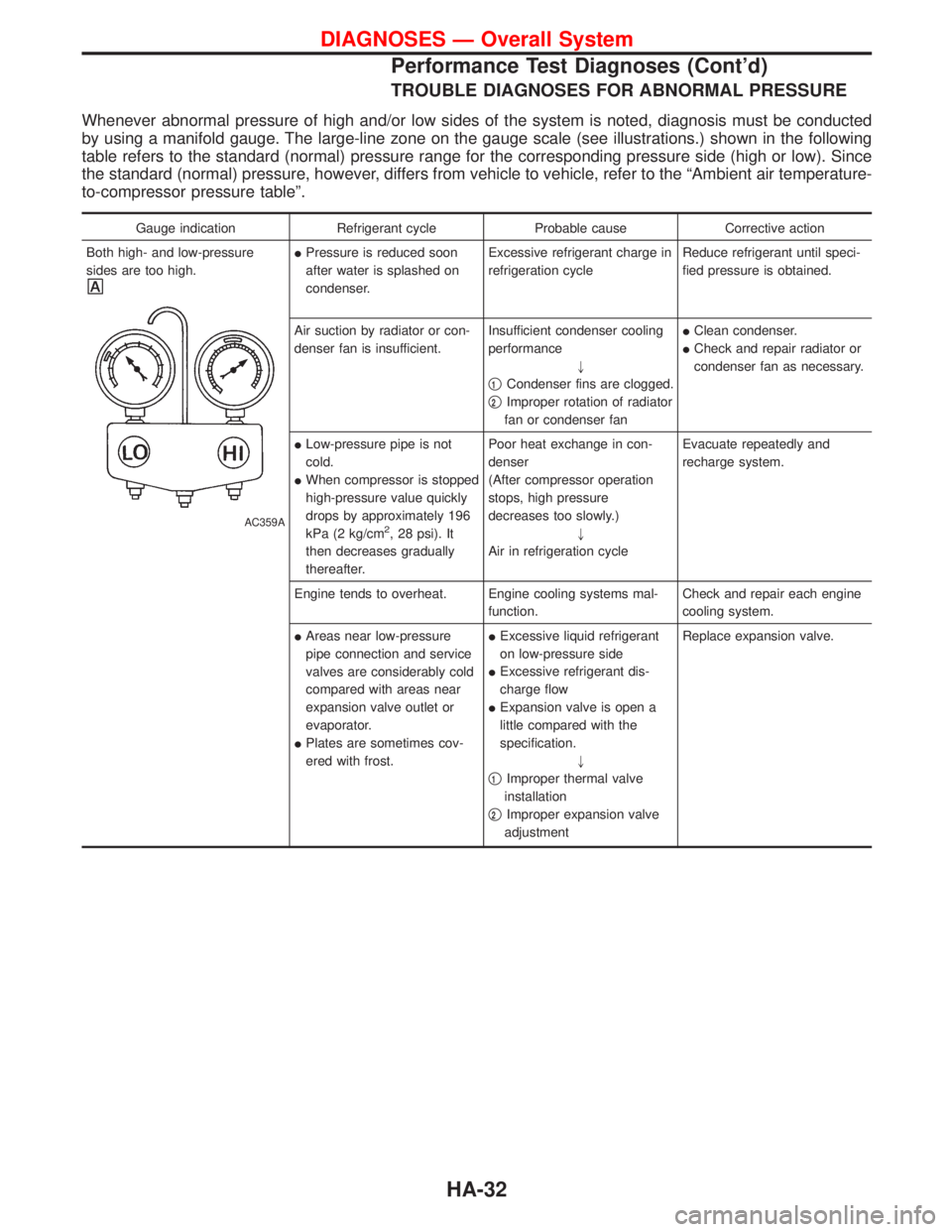
TROUBLE DIAGNOSES FOR ABNORMAL PRESSURE
Whenever abnormal pressure of high and/or low sides of the system is noted, diagnosis must be conducted
by using a manifold gauge. The large-line zone on the gauge scale (see illustrations.) shown in the following
table refers to the standard (normal) pressure range for the corresponding pressure side (high or low). Since
the standard (normal) pressure, however, differs from vehicle to vehicle, refer to the ªAmbient air temperature-
to-compressor pressure tableº.
Gauge indication Refrigerant cycle Probable cause Corrective action
Both high- and low-pressure
sides are too high.
AC359A
IPressure is reduced soon
after water is splashed on
condenser.Excessive refrigerant charge in
refrigeration cycleReduce refrigerant until speci-
fied pressure is obtained.
Air suction by radiator or con-
denser fan is insufficient.Insufficient condenser cooling
performance
"
q
1Condenser fins are clogged.
q
2Improper rotation of radiator
fan or condenser fanIClean condenser.
ICheck and repair radiator or
condenser fan as necessary.
ILow-pressure pipe is not
cold.
IWhen compressor is stopped
high-pressure value quickly
drops by approximately 196
kPa (2 kg/cm
2, 28 psi). It
then decreases gradually
thereafter.Poor heat exchange in con-
denser
(After compressor operation
stops, high pressure
decreases too slowly.)
"
Air in refrigeration cycleEvacuate repeatedly and
recharge system.
Engine tends to overheat. Engine cooling systems mal-
function.Check and repair each engine
cooling system.
IAreas near low-pressure
pipe connection and service
valves are considerably cold
compared with areas near
expansion valve outlet or
evaporator.
IPlates are sometimes cov-
ered with frost.IExcessive liquid refrigerant
on low-pressure side
IExcessive refrigerant dis-
charge flow
IExpansion valve is open a
little compared with the
specification.
"
q
1Improper thermal valve
installation
q
2Improper expansion valve
adjustmentReplace expansion valve.
DIAGNOSES Ð Overall System
Performance Test Diagnoses (Cont'd)
HA-32
Page 1422 of 1767

INT/V - Wiring diagram ................................EC-274
Intake air control valve control solenoid
valve .........................................................EC-273
Intake Air Volume .........................................EC-143
Intake door control linkage adjustment ..........HA-63
Intake manifold...............................................EM-12
Interior .............................................................BT-18
Interior lamp ..............................................EL-61, 66
ISO 15031-2 Terminology................................GI-35
K
Knuckle spindle ...............................................FA-20
L
License lamp ...................................................EL-45
Limited slip diff. adjustment............................PD-45
Limited slip diff. assembly ..............................PD-47
Limited slip diff. disassembly ...................PD-43, 44
Limited slip diff. inspection .............................PD-44
Line pressure solenoid valve ..........................AT-84
Line pressure test (A/T) ..........................AT-30, 196
Liquid gasket application .................................EM-3
Location of electrical units ............EL-241, 242, 244
Lock, door ...........................................BT-10, 12, 14
Low and reverse brake .................................AT-161
LSV (Load sensing valve) ..............................BR-10
Lubricants.......................................................MA-17
Lubrication circuit (engine) .........................LC-3, 20
Lubrication oil A/C ....................................HA-22, 64
Lubrication-locks, hinges and hood
latches ..................................................MA-36, 45
Luggage compartment trim .............................BT-18
M
MAFS - Wiring diagram..................................EC-90
MAIN - Wiring diagram...................................EC-80
Main drive gear (M/T) .....................................MT-11
Main gear (Transfer) .................................TF-10, 21
Mainshaft (M/T) ..............................................MT-11
Mainshaft (Transfer)..................................TF-10, 17
Maintenance ...........MA-5, 8, 11, 14, 20, 36, 48, 49
MAJOR OVERHALL ......................................AT-119
Major overhaul (Transfer) .................................TF-9
Malfunction indicator (MI).......................EC-34, 322
Manifold tightening torque (intake &
exhaust) ...............................................MA-20, 28
Manual transmission number ..........................GI-30
Manual transmission oil replacement ......MA-36, 37
Map lamp ........................................................EL-66
Mass air flow sensor (MAFS) ................EC-88, 356
Master cylinder (brake) ..................................BR-16
Meter .........................................................EL-70, 71
METER - Wiring diagram................................EL-72
MIL/DL - Wiring diagram ..............................EC-291MIRROR - Wiring diagram............................EL-131
Mirror, door......................................................BT-48
Model variation ................................................GI-28
Molding - See Exterior ....................................BT-21
M/T major overhaul ........................................MT-10
M/T removal and installation ........................MT-7, 8
Mud guard - See Exterior ...............................BT-21
MULTI - Wiring diagram................................EL-169
Multi-remote control system .........EL-168, 177, 179
Multiport fuel injection precautions ....................GI-5
N
NATS (Nissan anti-theft
system) .....................EL-186, 187, 188, 195, 208
NATS - Wiring diagram .................................EL-189
NATS V2.0 precautions (For Europe) ...............GI-4
Needle lift sensor .........................................EC-427
NVH troubleshooting (EM) ...............................EM-8
O
Oil change (capacity) ............MA-21, 29, 37, 38, 39
Oil change (interval) ..................................MA-5, 35
Oil cooler (engine) ............................................LC-8
Oil pan (engine) .............................................EM-22
Oil pump (A/T)...............................................AT-134
Oil seal replacement (engine)........................EM-50
Oil seal replacement (front final drive
4WD)...........................................................PD-10
OILPSW - Wiring diagram............................EC-451
On board diagnostic system ..................EC-33, 321
Overdrive control switch..................................AT-95
Overheat .......................................................EC-109
Overrun clutch solenoid valve ..................AT-69, 70
Oversize piston ..............................................EM-74
P
Park/Neutral position switch .........................EC-251
Park/neutral position switch (A/T) ...........AT-88, 114
Parking drum brake ........................................BR-35
Parking lamp ...................................................EL-45
PCV (positive crankcase ventilation) .....EC-23, 312
Periodic maintenance ......................................MA-5
Piston pin inspection ......................................EM-71
Piston ring inspection.....................................EM-72
PNP/SW - Wiring diagram ...........................EC-252
POWER - Wiring diagram.................................EL-8
Power door lock ...EL-137, 138, 145, 146, 148, 158
Power steering fluid level...............MA-36, 44, ST-4
Power steering gear .................................ST-12, 22
Power steering hydraulic pressure ...................ST-7
Power steering oil pump ...........................ST-16, 22
Power steering system bleeding.......................ST-5
Power supply routing ....................................EL-6, 8
Power window ...............................................EL-133
ALPHABETICAL INDEX
IDX-5
Page 1491 of 1767

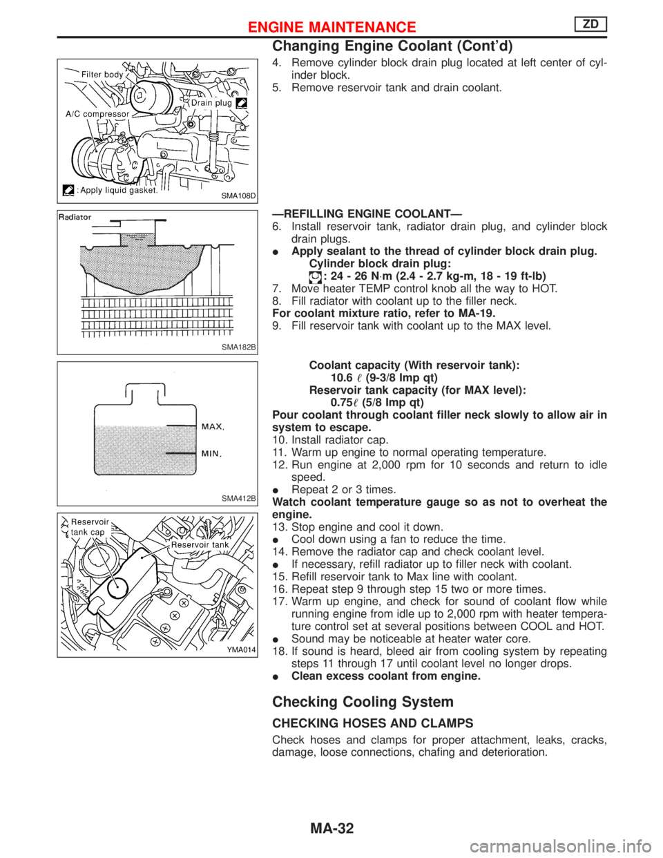
4. Remove cylinder block drain plug located at left center of cyl-
inder block.
5. Remove reservoir tank and drain coolant.
ÐREFILLING ENGINE COOLANTÐ
6. Install reservoir tank, radiator drain plug, and cylinder block
drain plugs.
IApply sealant to the thread of cylinder block drain plug.
Cylinder block drain plug:
:24-26N×m (2.4 - 2.7 kg-m, 18 - 19 ft-lb)
7. Move heater TEMP control knob all the way to HOT.
8. Fill radiator with coolant up to the filler neck.
For coolant mixture ratio, refer to MA-19.
9. Fill reservoir tank with coolant up to the MAX level.
Coolant capacity (With reservoir tank):
10.6(9-3/8 Imp qt)
Reservoir tank capacity (for MAX level):
0.75(5/8 Imp qt)
Pour coolant through coolant filler neck slowly to allow air in
system to escape.
10. Install radiator cap.
11. Warm up engine to normal operating temperature.
12. Run engine at 2,000 rpm for 10 seconds and return to idle
speed.
IRepeat 2 or 3 times.
Watch coolant temperature gauge so as not to overheat the
engine.
13. Stop engine and cool it down.
ICool down using a fan to reduce the time.
14. Remove the radiator cap and check coolant level.
IIf necessary, refill radiator up to filler neck with coolant.
15. Refill reservoir tank to Max line with coolant.
16. Repeat step 9 through step 15 two or more times.
17. Warm up engine, and check for sound of coolant flow while
running engine from idle up to 2,000 rpm with heater tempera-
ture control set at several positions between COOL and HOT.
ISound may be noticeable at heater water core.
18. If sound is heard, bleed air from cooling system by repeating
steps 11 through 17 until coolant level no longer drops.
IClean excess coolant from engine.
Checking Cooling System
CHECKING HOSES AND CLAMPS
Check hoses and clamps for proper attachment, leaks, cracks,
damage, loose connections, chafing and deterioration.
SMA108D
SMA182B
SMA412B
YMA014
ENGINE MAINTENANCEZD
Changing Engine Coolant (Cont'd)
MA-32