Page 1704 of 1767

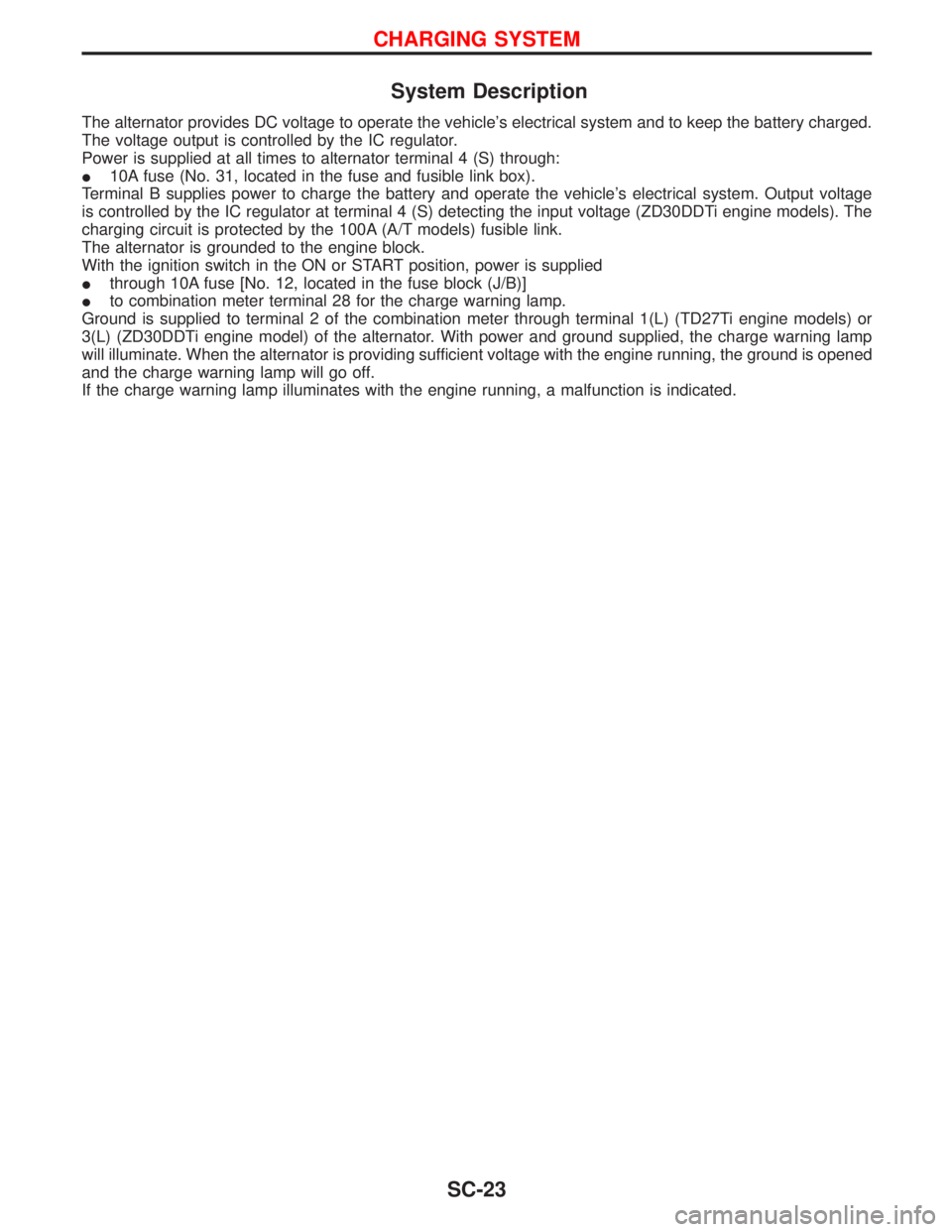
System Description
The alternator provides DC voltage to operate the vehicle's electrical system and to keep the battery charged.
The voltage output is controlled by the IC regulator.
Power is supplied at all times to alternator terminal 4 (S) through:
I10A fuse (No. 31, located in the fuse and fusible link box).
Terminal B supplies power to charge the battery and operate the vehicle's electrical system. Output voltage
is controlled by the IC regulator at terminal 4 (S) detecting the input voltage (ZD30DDTi engine models). The
charging circuit is protected by the 100A (A/T models) fusible link.
The alternator is grounded to the engine block.
With the ignition switch in the ON or START position, power is supplied
Ithrough 10A fuse [No. 12, located in the fuse block (J/B)]
Ito combination meter terminal 28 for the charge warning lamp.
Ground is supplied to terminal 2 of the combination meter through terminal 1(L) (TD27Ti engine models) or
3(L) (ZD30DDTi engine model) of the alternator. With power and ground supplied, the charge warning lamp
will illuminate. When the alternator is providing sufficient voltage with the engine running, the ground is opened
and the charge warning lamp will go off.
If the charge warning lamp illuminates with the engine running, a malfunction is indicated.
CHARGING SYSTEM
SC-23
Page 1707 of 1767
Trouble Diagnoses
Before conducting an alternator test, make sure that the battery is fully charged. A 30-volt voltmeter and suit-
able test probes are necessary for the test. The alternator can be checked easily by referring to the Inspec-
tion Table.
IBefore starting, inspect the fusible link.
IUse fully charged battery.
WITH IC REGULATOR
NOTE:
IIf the inspection result is OK even though the charging system is malfunctioning, check the B terminal
connection. (Check the tightening torque.)
IWhen field circuit is open, check condition of rotor coil, rotor slip ring and brush. If necessary, replace faulty
parts with new ones.
MALFUNCTION INDICATOR
The IC regulator warning function activates to illuminate ªCHARGEº warning lamp, if any of the following
symptoms occur while alternator is operating:
IExcessive voltage is produced.
INo voltage is produced.
SEL338V
CHARGING SYSTEM
SC-26
Page 1711 of 1767

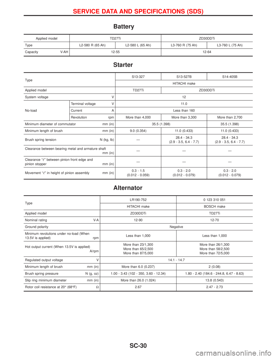
Battery
Applied model TD27Ti ZD30DDTi
Type L2-580 R (65 Ah) L2-580 L (65 Ah) L3-760 R (75 Ah) L3-760 L (75 Ah)
Capacity V-AH 12-55 12-64
Starter
TypeS13-327 S13-527B S14-405B
HITACHI make
Applied model TD27Ti ZD30DDTi
System voltage V 12
No-loadTerminal voltage V 11.0
Current A Less than 160
Revolution rpm More than 4,000 More than 3,300 More than 2,700
Minimum diameter of commutator mm (in) 35.5 (1.398) 35.5 (1.398)
Minimum length of brush mm (in) 9.0 (0.354) 11.0 (0.433) 11.0 (0.433)
Brush spring tension N (kg, lb) Ð28.4 - 34.3
(2.9 - 3.5, 6.4 - 7.7)28.4 - 34.3
(2.9 - 3.5, 6.4 - 7.7)
Clearance between bearing metal and armature shaft
mm (in)ÐÐÐ
Clearance ªº between pinion front edge and
pinion stopper mm (in)ÐÐÐ
Movement ªº in height of pinion assembly mm (in)0.3 - 1.5
(0.012 - 0.059)0.3 - 2.0
(0.012 - 0.079)0.3 - 2.0
(0.012 - 0.079)
Alternator
TypeLR190-752 0 123 310 051
HITACHI make BOSCH make
Applied model ZD30DDTi TD27Ti
Nominal rating V-A 12-90 12-70
Ground polarityNegative
Minimum revolutions under no-load (When
13.5V is applied) rpmLess than 1,000 Less than 1,000
Hot output current (When 13.5V is applied)
A/rpmMore than 23/1,300
More than 65/2,500
More than 87/5,000More than 26/1,300
More than 58/2,500
More than 72/5,000
Regulated output voltage V 14.1 - 14.7
Minimum length of brush mm (in) More than 6.0 (0.237) 2 (0.08)
Brush spring pressure N (g, oz) 1.00 - 3.43 (102 - 350, 3.60 - 12.34) 1.80 - 2.40 (184.6 - 244.8, 6.47 - 8.63)
Slip ring minimum diameter mm (in) More than 26.0 (1.024) 13.8 (0.543)
Rotor coil resistance at 20É (68ÉF)W2.67 2.47 - 2.73
SERVICE DATA AND SPECIFICATIONS (SDS)
SC-30
Page:
< prev 1-8 9-16 17-24