2002 NISSAN TERRANO low oil pressure
[x] Cancel search: low oil pressurePage 104 of 1767
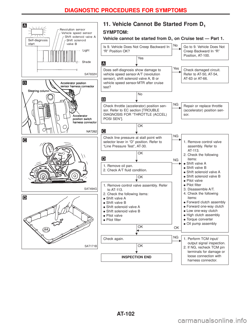
11. Vehicle Cannot Be Started From D1
SYMPTOM:
Vehicle cannot be started from D1on Cruise test Ð Part 1.
Is 9. Vehicle Does Not Creep Backward In
ªRº Position OK?
Ye s
ENo
Go to 9. Vehicle Does Not
Creep Backward In ªRº
Position, AT-100.
Does self-diagnosis show damage to
vehicle speed sensor×A/T (revolution
sensor), shift solenoid valve A, B or
vehicle speed sensor×MTR after cruise
test?
No
EYe s
Check damaged circuit.
Refer to AT-50, AT-54,
AT-63 or AT-66.
Check throttle (accelerator) position sen-
sor. Refer to EC section [TROUBLE
DIAGNOSIS FOR ªTHROTTLE (ACCEL)
POSI SENº].
OK
ENG
Repair or replace throttle
(accelerator) position sen-
sor.
Check line pressure at stall point with
selector lever in ªDº position. Refer to
ªLine Pressure Testº, AT-30.
OK
ENG
1. Remove control valve
assembly. Refer to
AT-113.
2. Check the following
items:
IShift valve A
IShift valve B
IShift solenoid valve A
IShift solenoid valve B
IPilot valve
IPilot filter
3. Disassemble A/T.
4. Check the following
items:
IForward clutch assembly
IForward one-way clutch
ILow one-way clutch
IHigh clutch assembly
ITorque converter
IOil pump assembly
1. Remove oil pan.
2. Check A/T fluid condition.
OK
ENG
1. Remove control valve assembly. Refer
to AT-113.
2. Check the following items:
IShift valve A
IShift valve B
IShift solenoid valve A
IShift solenoid valve B
IPilot valve
IPilot filter
OKFOK
Check again.
OK
ENG
1. Perform TCM input/
output signal inspection.
2. If NG, recheck TCM pin
terminals for damage or
loose connection with
harness connector.
INSPECTION END
SAT832H
NAT262
SAT494G
SAT171B
H
H
H
H
H
H H
H
DIAGNOSTIC PROCEDURES FOR SYMPTOMS
AT-102
Page 143 of 1767
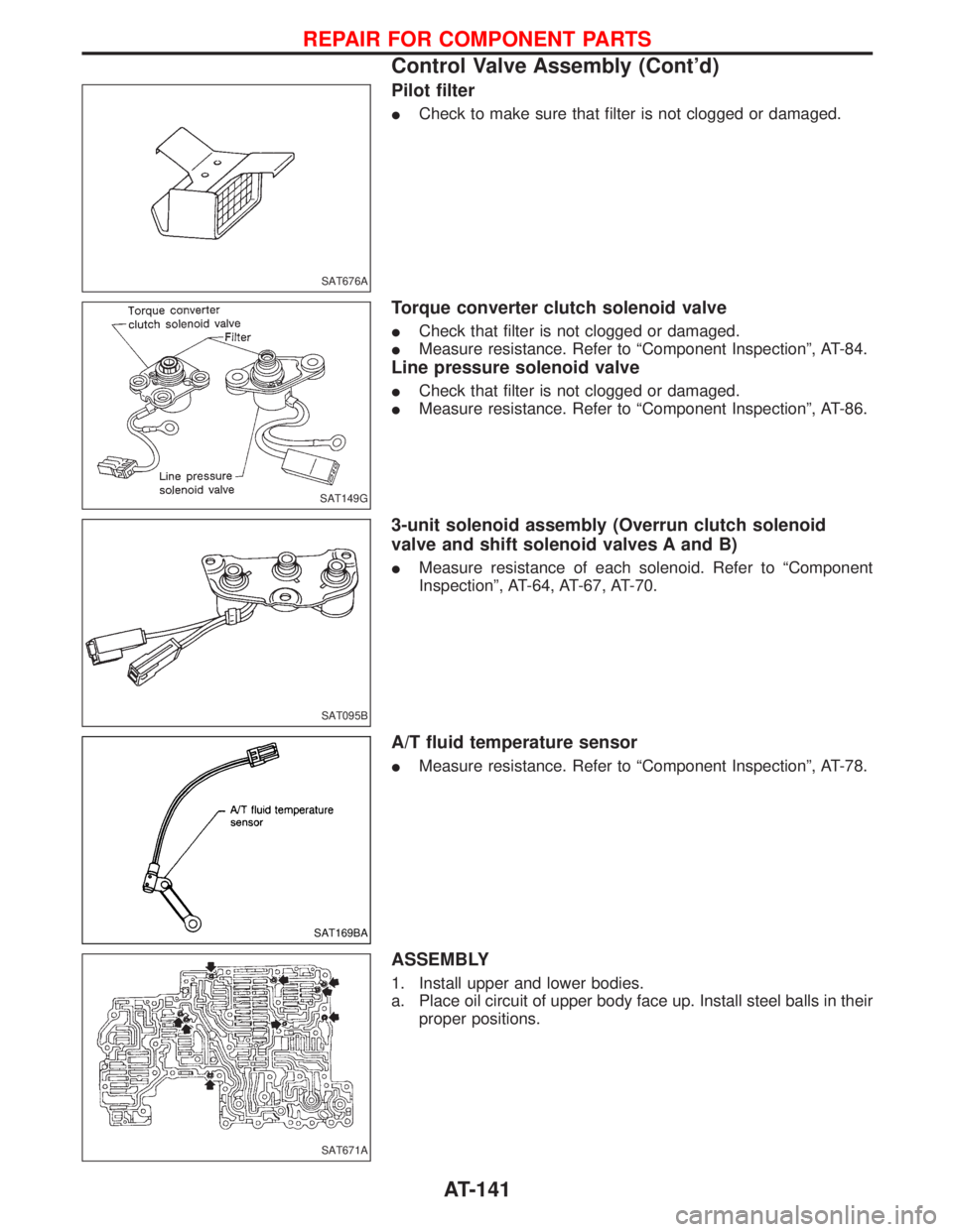
Pilot filter
ICheck to make sure that filter is not clogged or damaged.
Torque converter clutch solenoid valve
ICheck that filter is not clogged or damaged.
IMeasure resistance. Refer to ªComponent Inspectionº, AT-84.
Line pressure solenoid valve
ICheck that filter is not clogged or damaged.
IMeasure resistance. Refer to ªComponent Inspectionº, AT-86.
3-unit solenoid assembly (Overrun clutch solenoid
valve and shift solenoid valves A and B)
IMeasure resistance of each solenoid. Refer to ªComponent
Inspectionº, AT-64, AT-67, AT-70.
A/T fluid temperature sensor
IMeasure resistance. Refer to ªComponent Inspectionº, AT-78.
ASSEMBLY
1. Install upper and lower bodies.
a. Place oil circuit of upper body face up. Install steel balls in their
proper positions.
SAT676A
SAT149G
SAT095B
SAT169BA
SAT671A
REPAIR FOR COMPONENT PARTS
Control Valve Assembly (Cont'd)
AT-141
Page 207 of 1767
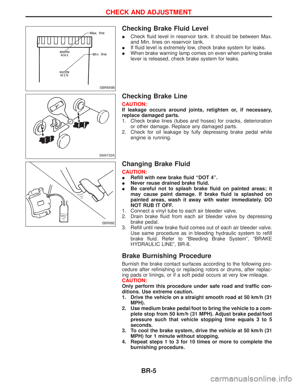
Checking Brake Fluid Level
ICheck fluid level in reservoir tank. It should be between Max.
and Min. lines on reservoir tank.
IIf fluid level is extremely low, check brake system for leaks.
IWhen brake warning lamp comes on even when parking brake
lever is released, check brake system for leaks.
Checking Brake Line
CAUTION:
If leakage occurs around joints, retighten or, if necessary,
replace damaged parts.
1. Check brake lines (tubes and hoses) for cracks, deterioration
or other damage. Replace any damaged parts.
2. Check for oil leakage by fully depressing brake pedal while
engine is running.
Changing Brake Fluid
CAUTION:
IRefill with new brake fluid ªDOT 4º.
INever reuse drained brake fluid.
IBe careful not to splash brake fluid on painted areas; it
may cause paint damage. If brake fluid is splashed on
painted areas, wash it away with water immediately. DO
NOT RUB IT OFF.
1. Connect a vinyl tube to each air bleeder valve.
2. Drain brake fluid from each air bleeder valve by depressing
brake pedal.
3. Refill until new brake fluid comes out of each air bleeder valve.
Use same procedure as in bleeding hydraulic system to refill
brake fluid. Refer to ªBleeding Brake Systemº, ªBRAKE
HYDRAULIC LINEº, BR-8.
Brake Burnishing Procedure
Burnish the brake contact surfaces according to the following pro-
cedure after refinishing or replacing rotors or drums, after replac-
ing pads or linings, or if a soft pedal occurs at very low mileage.
CAUTION:
Only perform this procedure under safe road and traffic con-
ditions. Use extreme caution.
1. Drive the vehicle on a straight smooth road at 50 km/h (31
MPH).
2. Use medium brake pedal/foot to bring the vehicle to a com-
plete stop from 50 km/h (31 MPH). Adjust brake pedal/foot
pressure such that vehicle stopping time equals 3 to 5
seconds.
3. To cool the brake system, drive the vehicle at 50 km/h (31
MPH) for 1 minute without stopping.
4. Repeat steps 1 to 3 for 10 times or more to complete the
burnishing procedure.
SBR849B
SMA732A
SBR992
CHECK AND ADJUSTMENT
BR-5
Page 215 of 1767
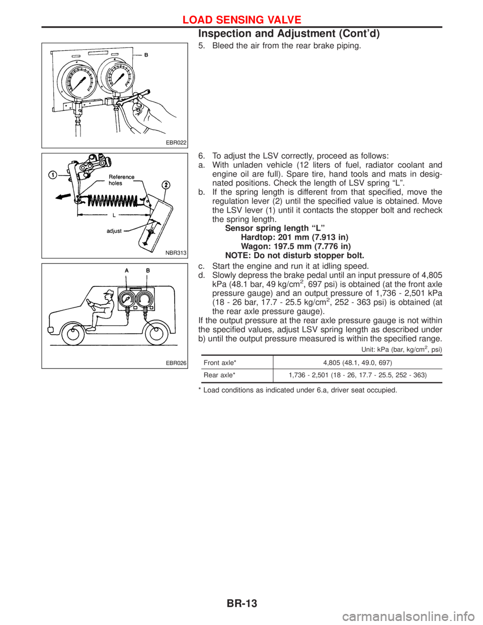
5. Bleed the air from the rear brake piping.
6. To adjust the LSV correctly, proceed as follows:
a. With unladen vehicle (12 liters of fuel, radiator coolant and
engine oil are full). Spare tire, hand tools and mats in desig-
nated positions. Check the length of LSV spring ªLº.
b. If the spring length is different from that specified, move the
regulation lever (2) until the specified value is obtained. Move
the LSV lever (1) until it contacts the stopper bolt and recheck
the spring length.
Sensor spring length ªLº
Hardtop: 201 mm (7.913 in)
Wagon: 197.5 mm (7.776 in)
NOTE: Do not disturb stopper bolt.
c. Start the engine and run it at idling speed.
d. Slowly depress the brake pedal until an input pressure of 4,805
kPa (48.1 bar, 49 kg/cm
2, 697 psi) is obtained (at the front axle
pressure gauge) and an output pressure of 1,736 - 2,501 kPa
(18 - 26 bar, 17.7 - 25.5 kg/cm
2, 252 - 363 psi) is obtained (at
the rear axle pressure gauge).
If the output pressure at the rear axle pressure gauge is not within
the specified values, adjust LSV spring length as described under
b) until the output pressure measured is within the specified range.
Unit: kPa (bar, kg/cm2, psi)
Front axle* 4,805 (48.1, 49.0, 697)
Rear axle* 1,736 - 2,501 (18 - 26, 17.7 - 25.5, 252 - 363)
* Load conditions as indicated under 6.a, driver seat occupied.
EBR022
NBR313
EBR026
LOAD SENSING VALVE
Inspection and Adjustment (Cont'd)
BR-13
Page 419 of 1767
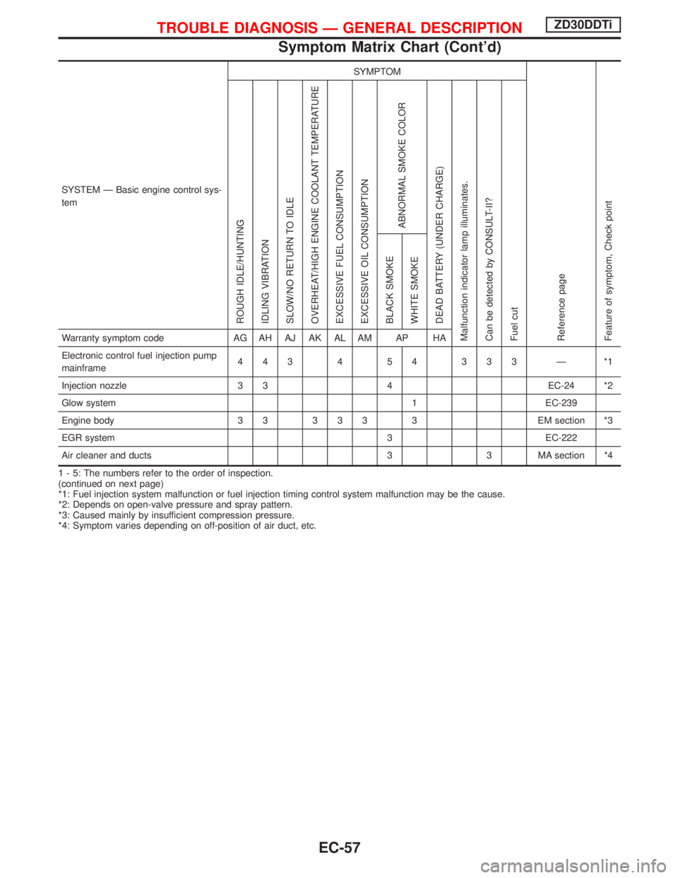
SYSTEM Ð Basic engine control sys-
temSYMPTOM
Reference page
Feature of symptom, Check pointROUGH IDLE/HUNTING
IDLING VIBRATION
SLOW/NO RETURN TO IDLE
OVERHEAT/HIGH ENGINE COOLANT TEMPERATURE
EXCESSIVE FUEL CONSUMPTION
EXCESSIVE OIL CONSUMPTION
ABNORMAL SMOKE COLOR
DEAD BATTERY (UNDER CHARGE)
Malfunction indicator lamp illuminates.
Can be detected by CONSULT-II?
Fuel cutBLACK SMOKE
WHITE SMOKEWarranty symptom code AG AH AJ AK AL AM AP HA
Electronic control fuel injection pump
mainframe443 4 54 333 Ð *1
Injection nozzle 3 3 4 EC-24 *2
Glow system 1 EC-239
Engine body 3 3 3 3 3 3 EM section *3
EGR system 3 EC-222
Air cleaner and ducts 3 3 MA section *4
1 - 5: The numbers refer to the order of inspection.
(continued on next page)
*1: Fuel injection system malfunction or fuel injection timing control system malfunction may be the cause.
*2: Depends on open-valve pressure and spray pattern.
*3: Caused mainly by insufficient compression pressure.
*4: Symptom varies depending on off-position of air duct, etc.
TROUBLE DIAGNOSIS Ð GENERAL DESCRIPTIONZD30DDTi
Symptom Matrix Chart (Cont'd)
EC-57
Page 423 of 1767
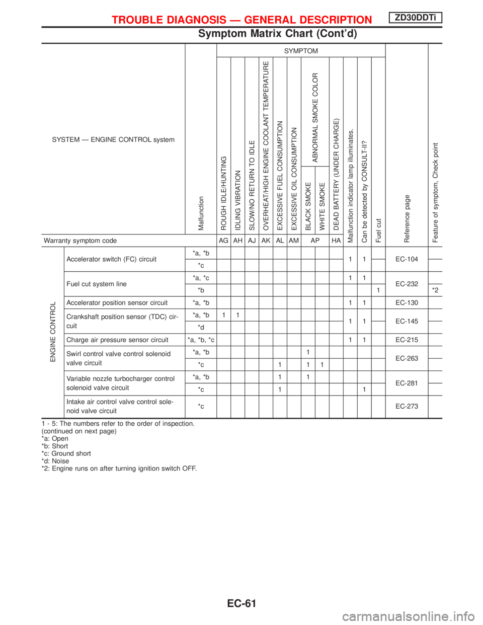
SYSTEM Ð ENGINE CONTROL system
Malfunction
SYMPTOM
Reference page
Feature of symptom, Check pointROUGH IDLE/HUNTING
IDLING VIBRATION
SLOW/NO RETURN TO IDLE
OVERHEAT/HIGH ENGINE COOLANT TEMPERATURE
EXCESSIVE FUEL CONSUMPTION
EXCESSIVE OIL CONSUMPTION
ABNORMAL SMOKE COLOR
DEAD BATTERY (UNDER CHARGE)
Malfunction indicator lamp illuminates.
Can be detected by CONSULT-II?
Fuel cutBLACK SMOKE
WHITE SMOKEWarranty symptom code AG AH AJ AK AL AM AP HA
ENGINE CONTROL
Accelerator switch (FC) circuit*a, *b
1 1 EC-104
*c
Fuel cut system line*a, *c 1 1
EC-232
*b 1 *2
Accelerator position sensor circuit *a, *b 1 1 EC-130
Crankshaft position sensor (TDC) cir-
cuit*a, *b 1 1
1 1 EC-145
*d
Charge air pressure sensor circuit *a, *b, *c 1 1 EC-215
Swirl control valve control solenoid
valve circuit*a, *b 1
EC-263
*c 1 1 1
Variable nozzle turbocharger control
solenoid valve circuit*a, *b 1 1
EC-281
*c 1 1
Intake air control valve control sole-
noid valve circuit*c EC-273
1 - 5: The numbers refer to the order of inspection.
(continued on next page)
*a: Open
*b: Short
*c: Ground short
*d: Noise
*2: Engine runs on after turning ignition switch OFF.
TROUBLE DIAGNOSIS Ð GENERAL DESCRIPTIONZD30DDTi
Symptom Matrix Chart (Cont'd)
EC-61
Page 702 of 1767
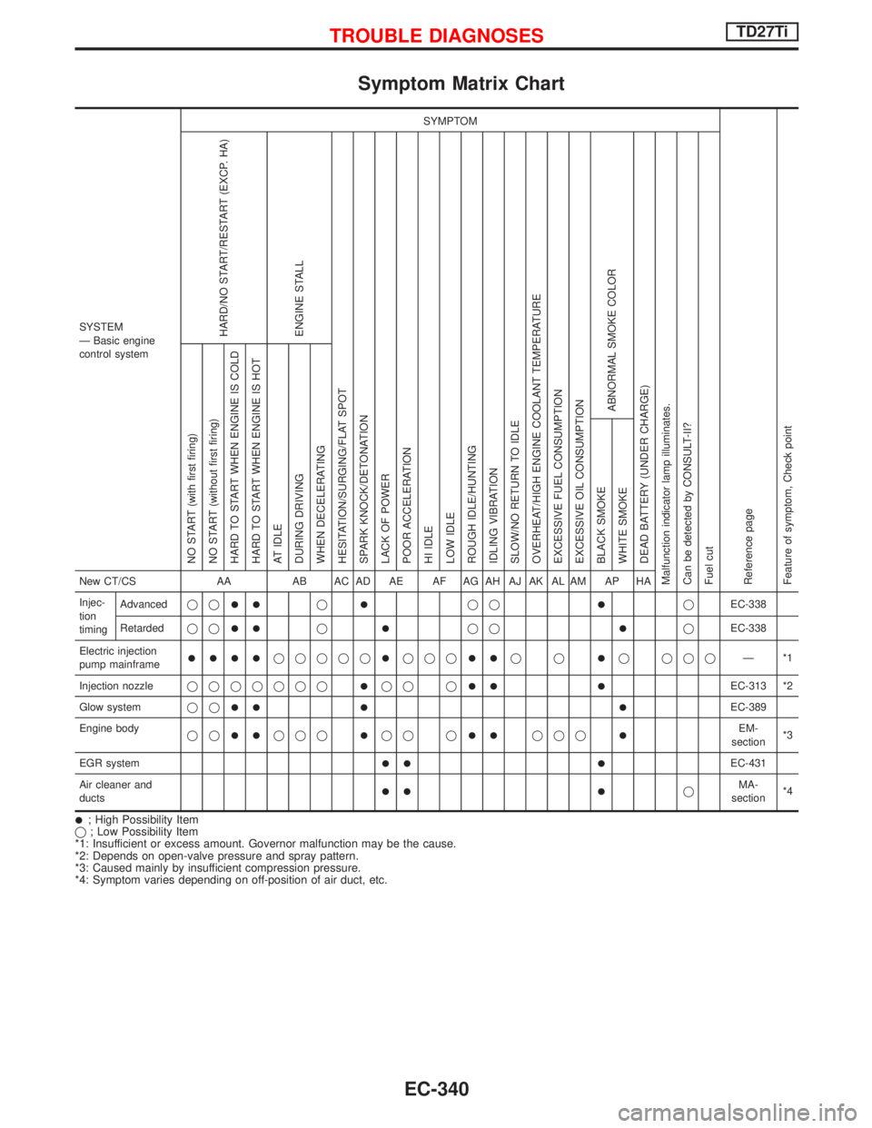
Symptom Matrix Chart
SYSTEM
Ð Basic engine
control systemSYMPTOM
Reference page
Feature of symptom, Check pointHARD/NO START/RESTART (EXCP. HA)
ENGINE STALL
HESITATION/SURGING/FLAT SPOT
SPARK KNOCK/DETONATION
LACK OF POWER
POOR ACCELERATION
HI IDLE
LOW IDLE
ROUGH IDLE/HUNTING
IDLING VIBRATION
SLOW/NO RETURN TO IDLE
OVERHEAT/HIGH ENGINE COOLANT TEMPERATURE
EXCESSIVE FUEL CONSUMPTION
EXCESSIVE OIL CONSUMPTION
ABNORMAL SMOKE COLOR
DEAD BATTERY (UNDER CHARGE)
Malfunction indicator lamp illuminates.
Can be detected by CONSULT-II?
Fuel cutNO START (with first firing)
NO START (without first firing)
HARD TO START WHEN ENGINE IS COLD
HARD TO START WHEN ENGINE IS HOT
AT IDLE
DURING DRIVING
WHEN DECELERATING
BLACK SMOKE
WHITE SMOKENew CT/CS AA AB AC AD AE AF AG AH AJ AK AL AM AP HA
Injec-
tion
timingAdvancedqq
IIqIqqIqEC-338
Retardedqq
IIqIqqIqEC-338
Electric injection
pump mainframe
IIIIqqqqqIqqqIIqqIq qqqÐ*1
Injection nozzleqqqqqqq
Iqq qII IEC-313 *2
Glow systemqq
II I IEC-389
Engine body
qq
IIqqqIqq qIIqqqIEM-
section*3
EGR system
II IEC-431
Air cleaner and
ducts
II IqMA-
section*4
I; High Possibility Item
q; Low Possibility Item
*1: Insufficient or excess amount. Governor malfunction may be the cause.
*2: Depends on open-valve pressure and spray pattern.
*3: Caused mainly by insufficient compression pressure.
*4: Symptom varies depending on off-position of air duct, etc.
TROUBLE DIAGNOSESTD27Ti
EC-340
Page 709 of 1767
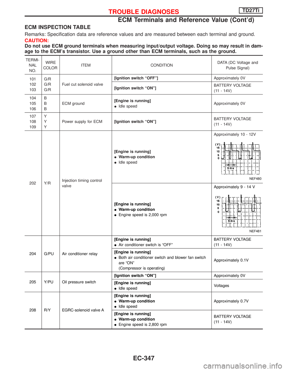
ECM INSPECTION TABLE
Remarks: Specification data are reference values and are measured between each terminal and ground.
CAUTION:
Do not use ECM ground terminals when measuring input/output voltage. Doing so may result in dam-
age to the ECM's transistor. Use a ground other than ECM terminals, such as the ground.
TERMI-
NAL
NO.WIRE
COLORITEM CONDITIONDATA (DC Voltage and
Pulse Signal)
101
102
103G/R
G/R
G/RFuel cut solenoid valve[Ignition switch ªOFFº]Approximately 0V
[Ignition switch ªONº]BATTERY VOLTAGE
(11 - 14V)
104
105
106B
B
BECM ground[Engine is running]
IIdle speedApproximately 0V
107
108
109Y
Y
YPower supply for ECM[Ignition switch ªONº]BATTERY VOLTAGE
(11 - 14V)
202 Y/RInjection timing control
valve[Engine is running]
IWarm-up condition
IIdle speedApproximately 10 - 12V
NEF480
[Engine is running]
IWarm-up condition
IEngine speed is 2,000 rpmApproximately9-14V
NEF481
204 G/PU Air conditioner relay[Engine is running]
IAir conditioner switch is ªOFFºBATTERY VOLTAGE
(11 - 14V)
[Engine is running]
IBoth air conditioner switch and blower fan switch
are ªONº
(Compressor is operating)Approximately 0.1V
205 Y/PU Oil pressure switch[Ignition switch ªONº]Approximately 0V
[Engine is running]
IIdle speedVoltages
208 R/Y EGRC-solenoid valve A[Engine is running]
IWarm-up condition
IIdle speedApproximately 0.7V
[Engine is running]
IWarm-up condition
IEngine speed is 2,800 rpmBATTERY VOLTAGE
(11 - 14V)
TROUBLE DIAGNOSESTD27Ti
ECM Terminals and Reference Value (Cont'd)
EC-347