2002 NISSAN TERRANO anti lock
[x] Cancel search: anti lockPage 245 of 1767
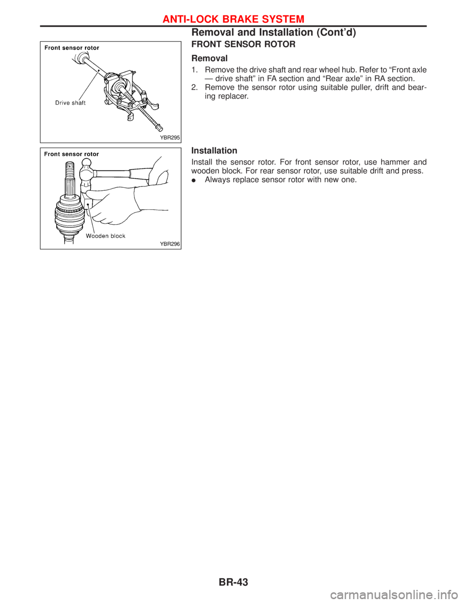
FRONT SENSOR ROTOR
Removal
1. Remove the drive shaft and rear wheel hub. Refer to ªFront axle
Ð drive shaftº in FA section and ªRear axleº in RA section.
2. Remove the sensor rotor using suitable puller, drift and bear-
ing replacer.
Installation
Install the sensor rotor. For front sensor rotor, use hammer and
wooden block. For rear sensor rotor, use suitable drift and press.
IAlways replace sensor rotor with new one.
YBR295
YBR296
ANTI-LOCK BRAKE SYSTEM
Removal and Installation (Cont'd)
BR-43
Page 246 of 1767
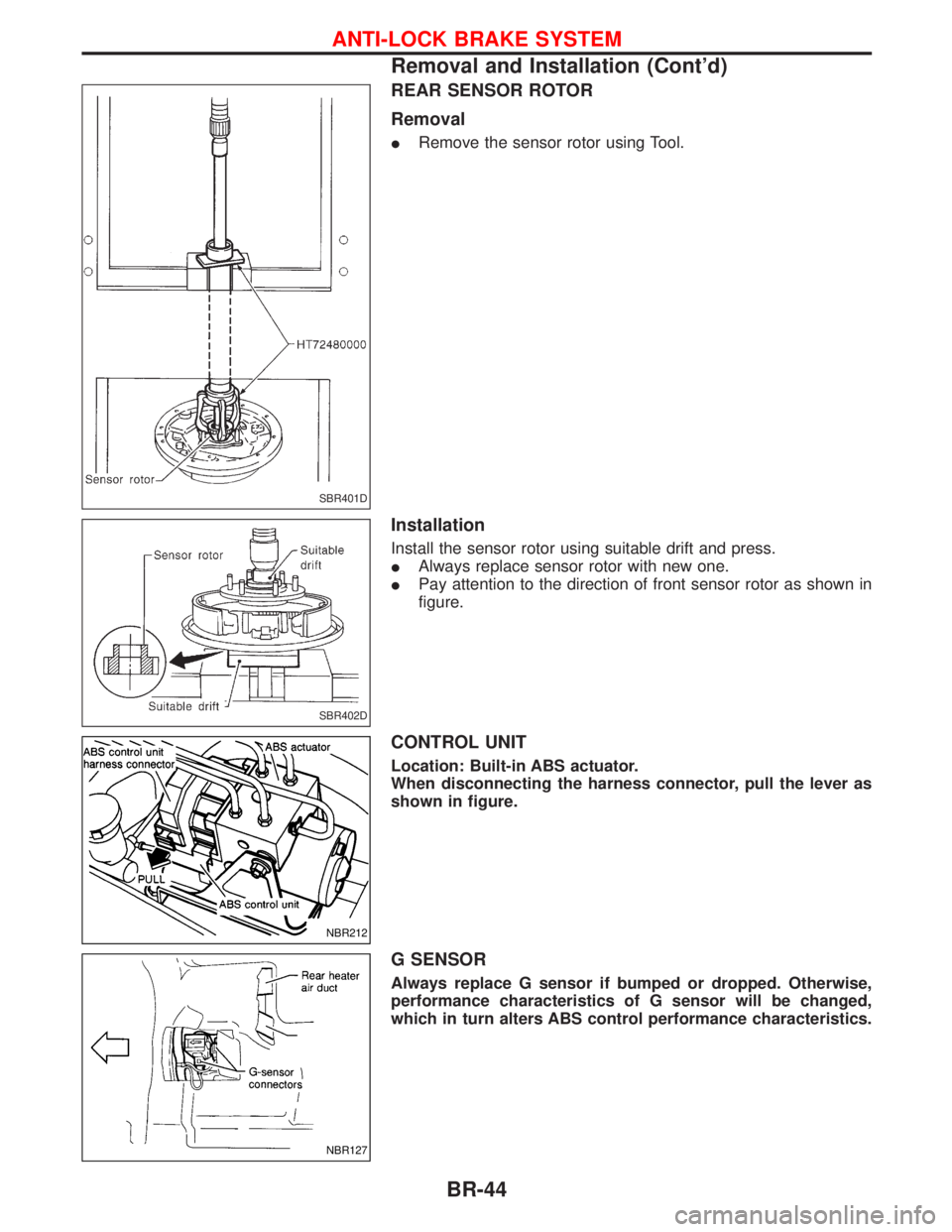
REAR SENSOR ROTOR
Removal
IRemove the sensor rotor using Tool.
Installation
Install the sensor rotor using suitable drift and press.
IAlways replace sensor rotor with new one.
IPay attention to the direction of front sensor rotor as shown in
figure.
CONTROL UNIT
Location: Built-in ABS actuator.
When disconnecting the harness connector, pull the lever as
shown in figure.
G SENSOR
Always replace G sensor if bumped or dropped. Otherwise,
performance characteristics of G sensor will be changed,
which in turn alters ABS control performance characteristics.
SBR401D
SBR402D
NBR212
NBR127
ANTI-LOCK BRAKE SYSTEM
Removal and Installation (Cont'd)
BR-44
Page 247 of 1767
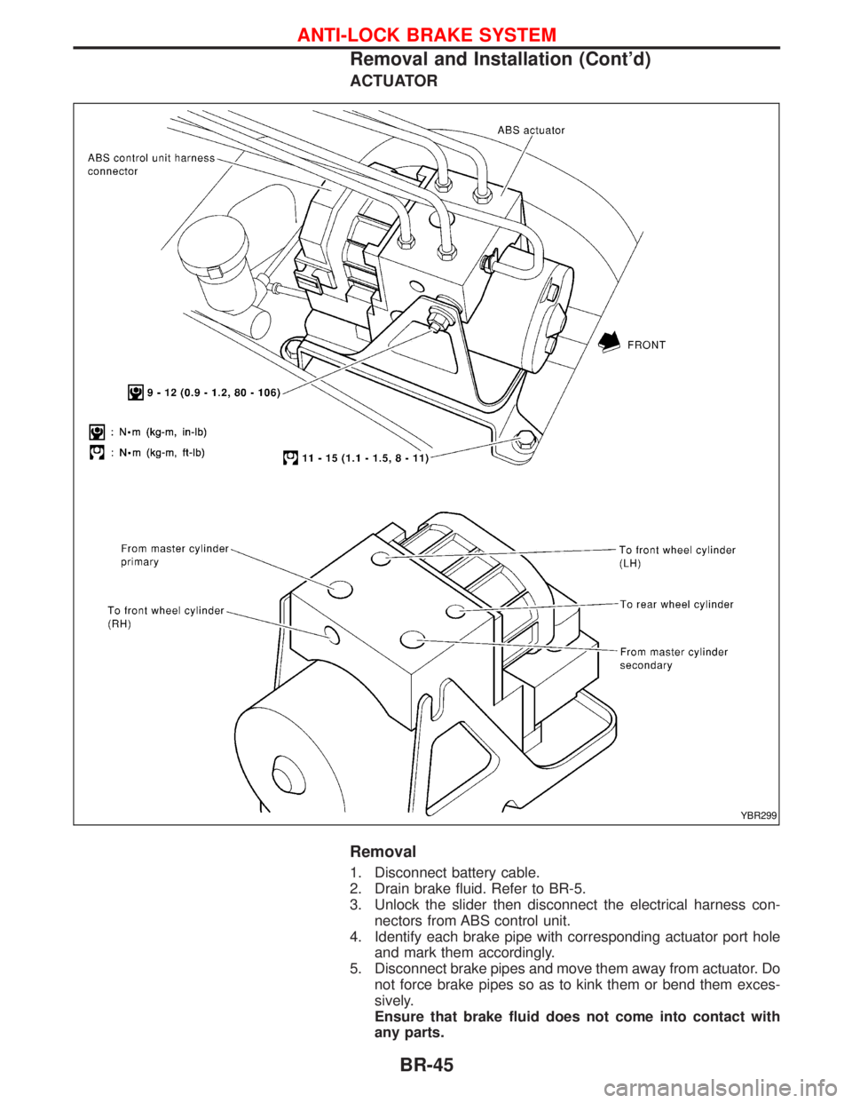
ACTUATOR
Removal
1. Disconnect battery cable.
2. Drain brake fluid. Refer to BR-5.
3. Unlock the slider then disconnect the electrical harness con-
nectors from ABS control unit.
4. Identify each brake pipe with corresponding actuator port hole
and mark them accordingly.
5. Disconnect brake pipes and move them away from actuator. Do
not force brake pipes so as to kink them or bend them exces-
sively.
Ensure that brake fluid does not come into contact with
any parts.
YBR299
ANTI-LOCK BRAKE SYSTEM
Removal and Installation (Cont'd)
BR-45
Page 248 of 1767
6. Loosen/remove mounting nuts between actuator and bracket.
Installation
CAUTION:
After installation, pay attention to the following points:
IRefill brake fluid and bleed air. Refer to ªCHECK AND
ADJUSTMENTº, BR-5 and ªBleeding Brake Systemº,
ªBRAKE HYDRAULIC LINEº, BR-8, respectively.
1. Install actuator on bracket without tightening fixings.
2. Assemble brake tubes to actuator without tightening tube nuts.
Ensure that correct tubes are connected to each port.
3. Fully tighten actuator and bracket fixings to specified torque.
4. Fully tighten flare nuts to specified torque, BR-9.
5. Secure ABS control unit harness connector and battery cable.
ANTI-LOCK BRAKE SYSTEM
Removal and Installation (Cont'd)
BR-46
Page 818 of 1767
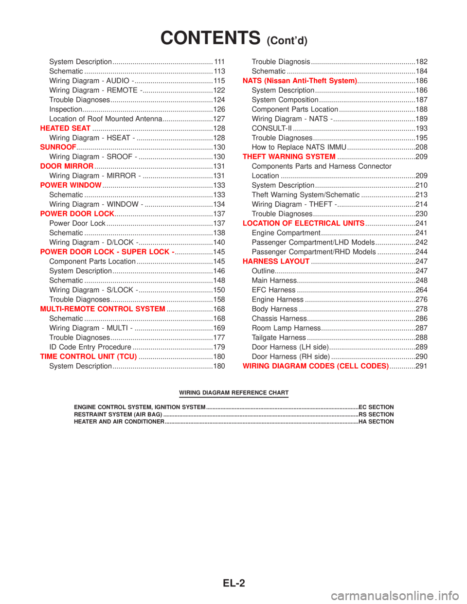
System Description .................................................. 111
Schematic ................................................................ 113
Wiring Diagram - AUDIO - ....................................... 115
Wiring Diagram - REMOTE -...................................122
Trouble Diagnoses...................................................124
Inspection.................................................................126
Location of Roof Mounted Antenna .........................127
HEATED SEAT............................................................128
Wiring Diagram - HSEAT - ......................................128
SUNROOF....................................................................130
Wiring Diagram - SROOF - .....................................130
DOOR MIRROR...........................................................131
Wiring Diagram - MIRROR - ...................................131
POWER WINDOW.......................................................133
Schematic ................................................................133
Wiring Diagram - WINDOW - ..................................134
POWER DOOR LOCK.................................................137
Power Door Lock .....................................................137
Schematic ................................................................138
Wiring Diagram - D/LOCK -.....................................140
POWER DOOR LOCK - SUPER LOCK -...................145
Component Parts Location ......................................145
System Description ..................................................146
Schematic ................................................................148
Wiring Diagram - S/LOCK - .....................................150
Trouble Diagnoses...................................................158
MULTI-REMOTE CONTROL SYSTEM.......................168
Schematic ................................................................168
Wiring Diagram - MULTI - .......................................169
Trouble Diagnoses...................................................177
ID Code Entry Procedure ........................................179
TIME CONTROL UNIT (TCU).....................................180
System Description ..................................................180Trouble Diagnosis ....................................................182
Schematic ................................................................184
NATS (Nissan Anti-Theft System).............................186
System Description ..................................................186
System Composition ................................................187
Component Parts Location ......................................188
Wiring Diagram - NATS -.........................................189
CONSULT-II .............................................................193
Trouble Diagnoses...................................................195
How to Replace NATS IMMU ..................................208
THEFT WARNING SYSTEM.......................................209
Components Parts and Harness Connector
Location ...................................................................209
System Description ..................................................210
Theft Warning System/Schematic ...........................213
Wiring Diagram - THEFT -.......................................214
Trouble Diagnoses...................................................230
LOCATION OF ELECTRICAL UNITS.........................241
Engine Compartment ...............................................241
Passenger Compartment/LHD Models ....................242
Passenger Compartment/RHD Models ...................244
HARNESS LAYOUT....................................................247
Outline......................................................................247
Main Harness...........................................................248
EFC Harness ...........................................................264
Engine Harness .......................................................276
Body Harness ..........................................................278
Chassis Harness......................................................286
Room Lamp Harness...............................................287
Tailgate Harness ......................................................288
Door Harness (LH side)...........................................289
Door Harness (RH side) ..........................................290
WIRING DIAGRAM CODES (CELL CODES).............291
WIRING DIAGRAM REFERENCE CHART
ENGINE CONTROL SYSTEM, IGNITION SYSTEM ................................................................................................EC SECTION
RESTRAINT SYSTEM (AIR BAG) ...........................................................................................................................RS SECTION
HEATER AND AIR CONDITIONER ..........................................................................................................................HA SECTION
CONTENTS(Cont'd)
EL-2
Page 962 of 1767
System Description
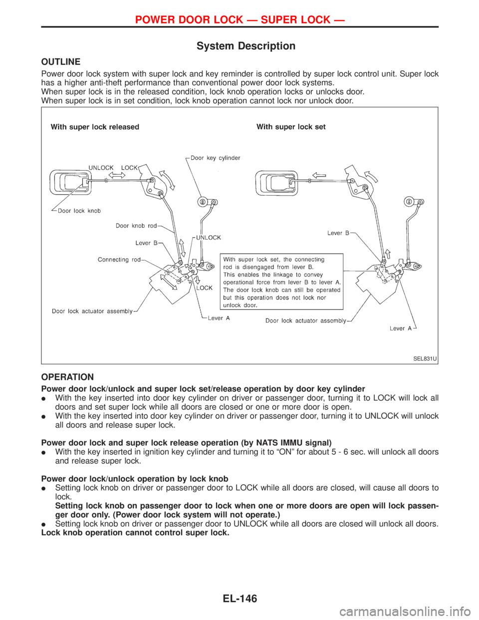
OUTLINE
Power door lock system with super lock and key reminder is controlled by super lock control unit. Super lock
has a higher anti-theft performance than conventional power door lock systems.
When super lock is in the released condition, lock knob operation locks or unlocks door.
When super lock is in set condition, lock knob operation cannot lock nor unlock door.
OPERATION
Power door lock/unlock and super lock set/release operation by door key cylinder
IWith the key inserted into door key cylinder on driver or passenger door, turning it to LOCK will lock all
doors and set super lock while all doors are closed or one or more door is open.
IWith the key inserted into door key cylinder on driver or passenger door, turning it to UNLOCK will unlock
all doors and release super lock.
Power door lock and super lock release operation (by NATS IMMU signal)
IWith the key inserted in ignition key cylinder and turning it to ªONº for about5-6sec. will unlock all doors
and release super lock.
Power door lock/unlock operation by lock knob
ISetting lock knob on driver or passenger door to LOCK while all doors are closed, will cause all doors to
lock.
Setting lock knob on passenger door to lock when one or more doors are open will lock passen-
ger door only. (Power door lock system will not operate.)
ISetting lock knob on driver or passenger door to UNLOCK while all doors are closed will unlock all doors.
Lock knob operation cannot control super lock.
SEL831U
POWER DOOR LOCK Ð SUPER LOCK Ð
EL-146
Page 1009 of 1767
CONSULT-II
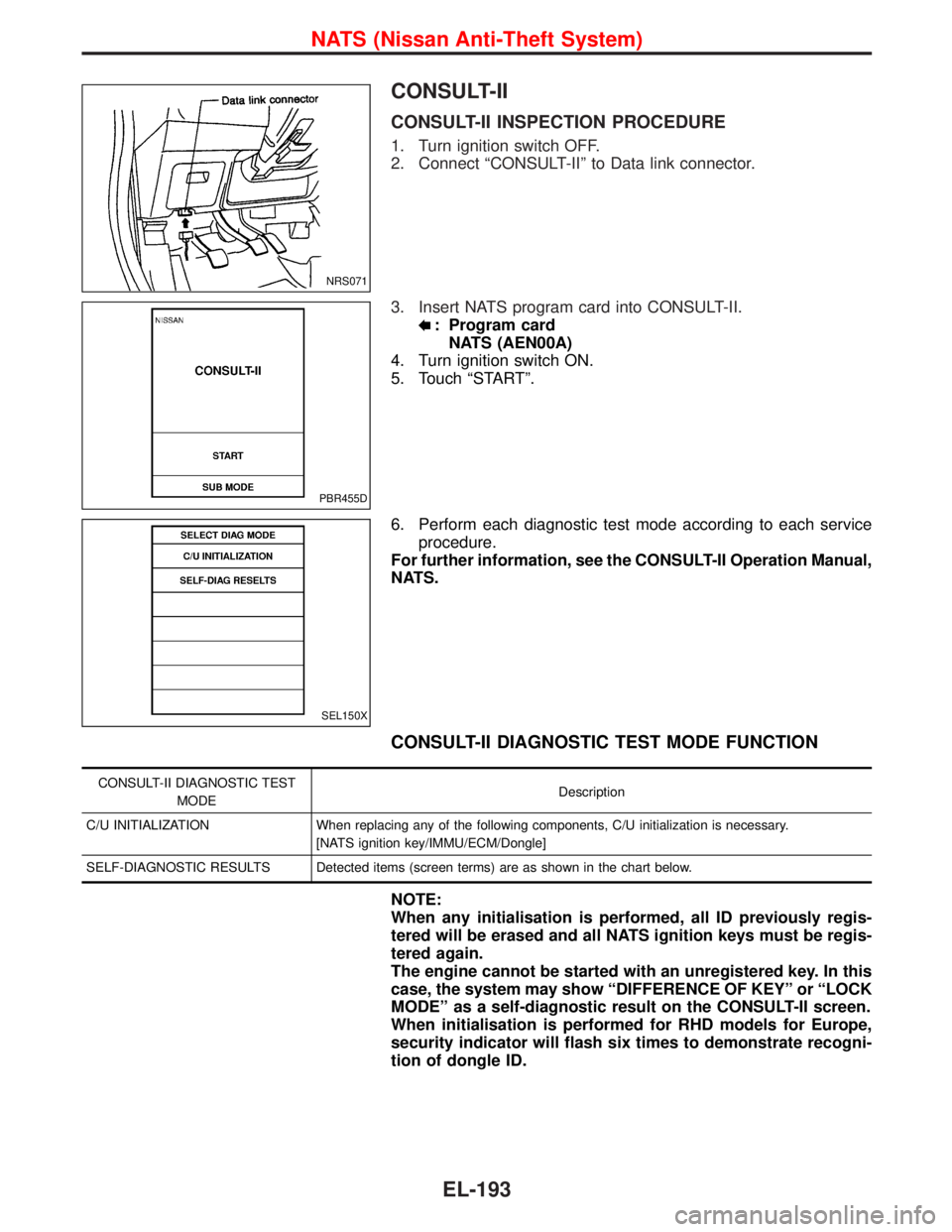
CONSULT-II INSPECTION PROCEDURE
1. Turn ignition switch OFF.
2. Connect ªCONSULT-IIº to Data link connector.
3. Insert NATS program card into CONSULT-II.
: Program card
NATS (AEN00A)
4. Turn ignition switch ON.
5. Touch ªSTARTº.
6. Perform each diagnostic test mode according to each service
procedure.
For further information, see the CONSULT-II Operation Manual,
NATS.
CONSULT-II DIAGNOSTIC TEST MODE FUNCTION
CONSULT-II DIAGNOSTIC TEST
MODEDescription
C/U INITIALIZATION When replacing any of the following components, C/U initialization is necessary.
[NATS ignition key/IMMU/ECM/Dongle]
SELF-DIAGNOSTIC RESULTS Detected items (screen terms) are as shown in the chart below.
NOTE:
When any initialisation is performed, all ID previously regis-
tered will be erased and all NATS ignition keys must be regis-
tered again.
The engine cannot be started with an unregistered key. In this
case, the system may show ªDIFFERENCE OF KEYº or ªLOCK
MODEº as a self-diagnostic result on the CONSULT-II screen.
When initialisation is performed for RHD models for Europe,
security indicator will flash six times to demonstrate recogni-
tion of dongle ID.
NRS071
PBR455D
SEL150X
NATS (Nissan Anti-Theft System)
EL-193
Page 1010 of 1767
HOW TO READ SELF-DIAGNOSTIC RESULTS
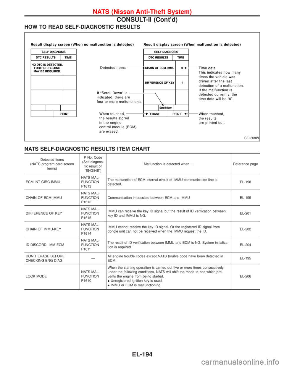
NATS SELF-DIAGNOSTIC RESULTS ITEM CHART
Detected items
(NATS program card screen
terms)P No. Code
(Self-diagnos-
tic result of
ªENGINEº)Malfunction is detected when ... Reference page
ECM INT CIRC-IMMUNATS MAL-
FUNCTION
P1613The malfunction of ECM internal circuit of IMMU communication line is
detected.EL-198
CHAIN OF ECM-IMMUNATS MAL-
FUNCTION
P1612Communication impossible between ECM and IMMU EL-199
DIFFERENCE OF KEYNATS MAL-
FUNCTION
P1615IMMU can receive the key ID signal but the result of ID verification between
key ID and IMMU is NG.EL-201
CHAIN OF IMMU-KEYNATS MAL-
FUNCTION
P1614IMMU cannot receive the key ID signal. Or the registered ID signal from
dongle unit can not be received when the IMMU request the ID.EL-202
ID DISCORD, IMM-ECMNATS MAL-
FUNCTION
P1611The result of ID verification between IMMU and ECM is NG. System initializa-
tion is required.EL-204
DON'T ERASE BEFORE
CHECKING ENG DIAGÐAll engine trouble codes except NATS trouble code have been detected in
ECM.EL-195
LOCK MODENATS MAL-
FUNCTION
P1610When the starting operation is carried out five or more times consecutively
under the following conditions, NATS will shift the mode to one which pre-
vents the engine from being started.
IUnregistered ignition key is used.
IIMMU or ECM is malfunctioning.EL-206
SEL308W
NATS (Nissan Anti-Theft System)
CONSULT-II (Cont'd)
EL-194