2002 NISSAN TERRANO anti lock
[x] Cancel search: anti lockPage 1012 of 1767
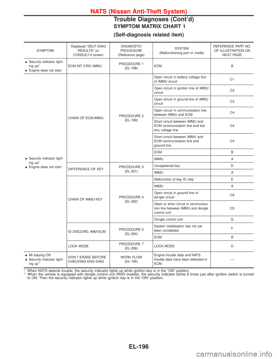
SYMPTOM MATRIX CHART 1
(Self-diagnosis related item)
SYMPTOMDisplayed ªSELF-DIAG
RESULTSº on
CONSULT-II screenDIAGNOSTIC
PROCEDURE
(Reference page)SYSTEM
(Malfunctioning part or mode)REFERENCE PART NO.
OF ILLUSTRATION ON
NEXT PAGE
ISecurity indicator light-
ing up*
IEngine does not startECM INT CIRC-IMMUPROCEDURE 1
(EL-198)ECM B
ISecurity indicator light-
ing up*
IEngine does not startCHAIN OF ECM-IMMUPROCEDURE 2
(EL-199)Open circuit in battery voltage line
of IMMU circuitC1
Open circuit in ignition line of IMMU
circuitC2
Open circuit in ground line of IMMU
circuitC3
Open circuit in communication line
between IMMU and ECMC4
Short circuit between IMMU and
ECM communication line and bat-
tery voltage lineC4
Short circuit between IMMU and
ECM communication line and
ground lineC4
ECM B
IMMU A
DIFFERENCE OF KEYPROCEDURE 3
(EL-201)Unregistered key D
IMMU A
CHAIN OF IMMU-KEYPROCEDURE 4
(EL-202)Malfunction of key ID chip E
IMMU A
Open circuit in ground line of
dongle circuitC6
Open or short circuit in communica-
tion line between IMMU and dongle
control unitC5
Dongle control unit G
ID DISCORD, IMM-ECMPROCEDURE 5
(EL-204)System initialisation has not yet
been completed.F
ECM B
LOCK MODEPROCEDURE 7
(EL-206)LOCK MODE D
IMI staying ON
ISecurity indicator light-
ing up*DON'T ERASE BEFORE
CHECKING ENG DIAGWORK FLOW
(EL-195)Engine trouble data and NATS
trouble data have been detected in
ECM.Ð
*: When NATS detects trouble, the security indicator lights up while ignition key is in the ªONº position.
*: When the vehicle is equipped with dongle control unit (RHD models), the security indicator blinks 6 times just after ignition switch is turned
to ON. Then the security indicator lights up while ignition key is in the ªONº position.
NATS (Nissan Anti-Theft System)
Trouble Diagnoses (Cont'd)
EL-196
Page 1015 of 1767
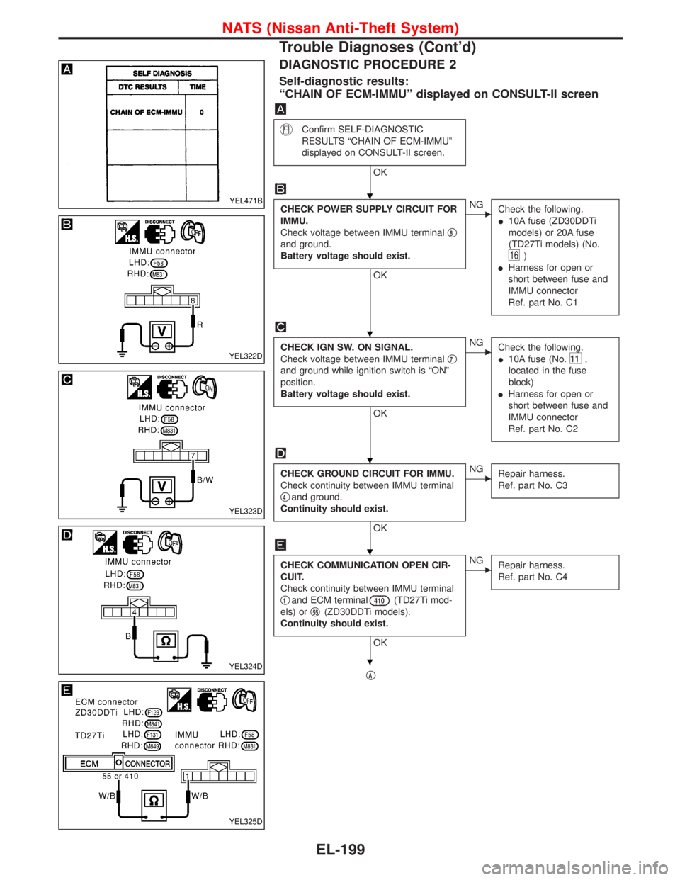
DIAGNOSTIC PROCEDURE 2
Self-diagnostic results:
ªCHAIN OF ECM-IMMUº displayed on CONSULT-II screen
Confirm SELF-DIAGNOSTIC
RESULTS ªCHAIN OF ECM-IMMUº
displayed on CONSULT-II screen.
OK
CHECK POWER SUPPLY CIRCUIT FOR
IMMU.
Check voltage between IMMU terminalq
8
and ground.
Battery voltage should exist.
OK
ENG
Check the following.
I10A fuse (ZD30DDTi
models) or 20A fuse
(TD27Ti models) (No.
16)
IHarness for open or
short between fuse and
IMMU connector
Ref. part No. C1
CHECK IGN SW. ON SIGNAL.
Check voltage between IMMU terminalq
7
and ground while ignition switch is ªONº
position.
Battery voltage should exist.
OK
ENG
Check the following.
I10A fuse (No.
11 ,
located in the fuse
block)
IHarness for open or
short between fuse and
IMMU connector
Ref. part No. C2
CHECK GROUND CIRCUIT FOR IMMU.
Check continuity between IMMU terminal
q
4and ground.
Continuity should exist.
OK
ENG
Repair harness.
Ref. part No. C3
CHECK COMMUNICATION OPEN CIR-
CUIT.
Check continuity between IMMU terminal
q
1and ECM terminal410(TD27Ti mod-
els) orq
55(ZD30DDTi models).
Continuity should exist.
OK
ENG
Repair harness.
Ref. part No. C4
qA
YEL471B
YEL322D
YEL323D
YEL324D
YEL325D
H
H
H
H
H
NATS (Nissan Anti-Theft System)
Trouble Diagnoses (Cont'd)
EL-199
Page 1021 of 1767
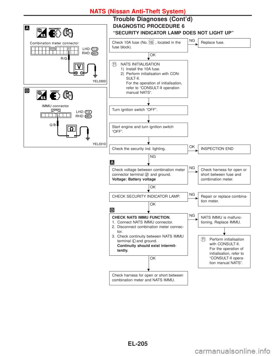
DIAGNOSTIC PROCEDURE 6
ªSECURITY INDICATOR LAMP DOES NOT LIGHT UPº
Check 10A fuse (No.16 , located in the
fuse block).
OK
ENG
Replace fuse.
NATS INITIALISATION
1) Install the 10A fuse.
2) Perform initialisation with CON-
SULT-II.
For the operation of initialisation,
refer to ªCONSULT-II operation
manual NATSº.
Turn ignition switch ªOFFº.
Start engine and turn ignition switch
ªOFFº.
Check the security ind. lighting.
NG
EOK
INSPECTION END
Check voltage between combination meter
connector terminalq
27and ground.
Voltage: Battery voltage
OK
ENG
Check harness for open or
short between fuse and
combination meter.
CHECK SECURITY INDICATOR LAMP.
OK
ENG
Repair or replace combina-
tion meter.
CHECK NATS IMMU FUNCTION.
1. Connect NATS IMMU connector.
2. Disconnect combination meter connec-
tor.
3. Check continuity between NATS IMMU
terminalq
5and ground.
Continuity should exist intermit-
tently.
OK
ENG
NATS IMMU is malfunc-
tioning. Replace IMMU.
Perform initialisation
with CONSULT-II.
For the operation of
initialisation, refer to
ªCONSULT-II opera-
tion manual NATSº.
Check harness for open or short between
combination meter and NATS IMMU.
YEL330D
YEL331D
H
H
H
H
H
H
H
H
H
NATS (Nissan Anti-Theft System)
Trouble Diagnoses (Cont'd)
EL-205
Page 1022 of 1767
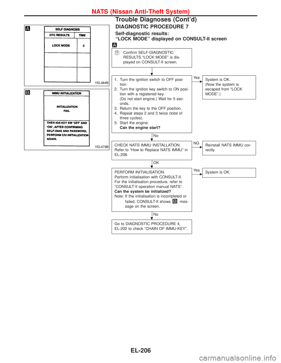
DIAGNOSTIC PROCEDURE 7
Self-diagnostic results:
ªLOCK MODEº displayed on CONSULT-II screen
Confirm SELF-DIAGNOSTIC
RESULTS ªLOCK MODEº is dis-
played on CONSULT-II screen.
1. Turn the ignition switch to OFF posi-
tion.
2. Turn the ignition key switch to ON posi-
tion with a registered key.
(Do not start engine.) Wait for 5 sec-
onds.
3. Return the key to the OFF position.
4. Repeat steps 2 and 3 twice (total of
three cycles).
5. Start the engine.
Can the engine start?
No
EYe s
System is OK.
(Now the system is
escaped from ªLOCK
MODEº.)
CHECK NATS IMMU INSTALLATION.
Refer to ªHow to Replace NATS IMMUº in
EL-208.
OK
ENG
Reinstall NATS IMMU cor-
rectly.
PERFORM INITIALISATION.
Perform initialisation with CONSULT-II.
For the initialisation procedure, refer to
ªCONSULT-II operation manual NATSº.
Can the system be initialized?
Note: If the initialisation is incompleted or
failed, CONSULT-II shows
mes-
sage on the screen.
No
EYe s
System is OK.
Go to DIAGNOSTIC PROCEDURE 4,
EL-202 to check ªCHAIN OF IMMU-KEYº.
YEL484B
YEL479B
H
H
H
H
NATS (Nissan Anti-Theft System)
Trouble Diagnoses (Cont'd)
EL-206
Page 1024 of 1767

How to Replace NATS IMMU
NOTE:
IIf NATS IMMU is not installed correctly, NATS system will
not operate properly and SELF-DIAG RESULTS on CON-
SULT-II screen will show ªLOCK MODEº or ªCHAIN OF
IMMU-KEYº.
SEL096WA
NATS (Nissan Anti-Theft System)
EL-208
Page 1048 of 1767
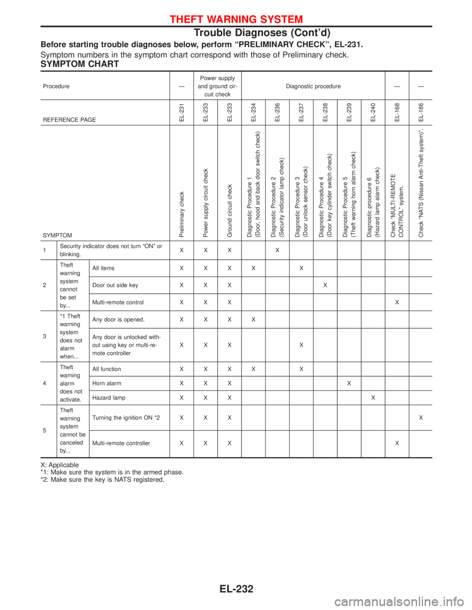
Before starting trouble diagnoses below, perform ªPRELIMINARY CHECKº, EL-231.
Symptom numbers in the symptom chart correspond with those of Preliminary check.
SYMPTOM CHART
Procedure ÐPower supply
and ground cir-
cuit checkDiagnostic procedure Ð Ð
REFERENCE PAGE
EL-231
EL-233
EL-233
EL-234
EL-236
EL-237
EL-238
EL-239
EL-240
EL-168
EL-186
SYMPTOMPreliminary check
Power supply circuit check
Ground circuit check
Diagnostic Procedure 1
(Door, hood and back door switch check)
Diagnostic Procedure 2
(Security indicator lamp check)
Diagnostic Procedure 3
(Door unlock sensor check)
Diagnostic Procedure 4
(Door key cylinder switch check)
Diagnostic Procedure 5
(Theft warning horn alarm check)
Diagnostic procedure 6
(Hazard lamp alarm check)
Check ªMULTI-REMOTE
CONTROLº system.
Check ªNATS (Nissan Anti-Theft system)º.
1Security indicator does not turn ªONº or
blinking.XXX X
2Theft
warning
system
cannot
be set
by...All itemsXXXX X
Door out side key X X X X
Multi-remote control X X X X
3*1 Theft
warning
system
does not
alarm
when...Any door is opened.XXXX
Any door is unlocked with-
out using key or multi-re-
mote controllerXXX X
4Theft
warning
alarm
does not
activate.All functionXXXX X
Horn alarm X X X X
Hazard lamp X X X X
5Theft
warning
system
cannot be
canceled
by...Turning the ignition ON *2 X X XX
Multi-remote controller X X X X
X: Applicable
*1: Make sure the system is in the armed phase.
*2: Make sure the key is NATS registered.
THEFT WARNING SYSTEM
Trouble Diagnoses (Cont'd)
EL-232
Page 1107 of 1767
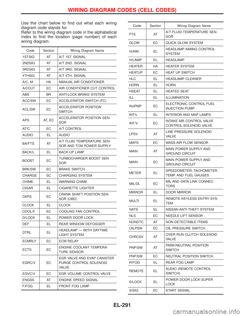
Use the chart below to find out what each wiring
diagram code stands for.
Refer to the wiring diagram code in the alphabetical
index to find the location (page number) of each
wiring diagram.
Code Section Wiring Diagram Name
1STSIG AT A/T 1ST. SIGNAL
2NDSIG AT A/T 2ND. SIGNAL
3RDSIG AT A/T 3RD. SIGNAL
4THSIG AT A/T 4TH. SIGNAL
A/C, M HA MANUAL AIR CONDITIONER
A/CCUT EC AIR CONDITIONER CUT CONTROL
ABS BR ANTI-LOCK BRAKE SYSTEM
ACC/SW EC ACCELERATOR SWITCH (FC)
ACL/SW ECACCELERATOR POSITION
SWITCH
APS AT, ECACCELERATOR POSITION SEN-
SOR
AT/C EC A/T CONTROL
AUDIO EL AUDIO
BA/FTS ATA/T FLUID TEMPERATURE SEN-
SOR AND TCM POWER SUPPLY
BACK/L EL BACK-UP LAMP
BOOST ECTURBOCHARGER BOOST SEN-
SOR
BRK/SW EC BRAKE SWITCH
CHARGE SC CHARGING SYSTEM
CHIME EL WARNING CHIME
CIGAR EL CIGARETTE LIGHTER
CKPS ECCRANK SHAFT POSITION SEN-
SOR (OBD)
CLOCK EL CLOCK
COOL/F EC COOLING FAN CONTROL
D/LOCK EL POWER DOOR LOCK
DEF EL REAR WINDOW DEFOGGER
DTRL ELHEADLAMP Ð WITH DAYTIME
LIGHT SYSTEM
ECMRLY EC ECM RELAY
ECTS ECENGINE COOLANT TEMPERA-
TURE SENSOR
EGRC/V ECEGR VALVE AND EVAP CANISTER
PURGE CONTROL SOLENOID
VA LV E
EGVC/V EC EGR VOLUME CONTROL VALVE
ENGSS AT ENGINE SPEED SIGNAL
F/FOG EL FRONT FOG LAMP
Code Section Wiring Diagram Name
FTS ATA/T FLUID TEMPERATURE SEN-
SOR
GLOW EC QUICK GLOW SYSTEM
H/AIM ELHEADLAMP AIMING CONTROL
SYSTEM
H/LAMP EL HEADLAMP
HEATER HA HEATER SYSTEM
HEATUP EC HEAT UP SWITCH
HLC EL HEADLAMP CLEANER
HORN EL HORN
HSEAT EL HEATED SEAT
ILL EL ILLUMINATION
INJPMP ECELECTRONIC CONTROL FUEL
INJECTION PUMP
INT/L EL INTERIOR AND MAP LAMPS
INT/V ECINTAKE AIR CONTROL VALVE
CONTROL SOLENOID VALVE
LPSV ATLINE PRESSURE SOLENOID
VA LV E
MAFS EC MASS AIR FLOW SENSOR
MAIN ATMAIN POWER SUPPLY AND
GROUND CIRCUIT
MAIN ECMAIN POWER SUPPLY AND
GROUND CIRCUIT
METER ELSPEEDOMETER, TACHOMETER,
TEMP. AND FUEL GAUGES
MIL/DL ECMIL AND DATA LINK CONNEC-
TORS
MIRROR EL DOOR MIRROR
MULTI ELREMOTE KEYLESS ENTRY SYS-
TEM
NATS EL NISSAN ANTI-THEFT SYSTEM
NLS EC NEEDLE LIFT SENSOR
NONDTC AT NON-DETECTABLE ITEMS
OILPSW EC OIL PRESSURE SWITCH
OVRCSV ATOVER RUN CLUTCH SOLENOID
VA LV E
PNP/SW ATPARK/NEUTRAL POSITION
SWITCH
PNP/SW EC NEUTRAL POSITION SWITCH
R/FOG EL REAR FOG LAMP
REMOTE ELAUDIO (REMOTE CONTROL
SWITCH)
S/LOCK ELPOWER DOOR LOCK-SUPER
LOCK
S/SIG EC START SIGNAL
WIRING DIAGRAM CODES (CELL CODES)
EL-291
Page 1419 of 1767
A
ABS (anti-lock brake system).........................BR-35
ABS - Wiring diagram ....................................BR-50
A/C air flow .......................................................HA-8
A/C compressor precaution..............................HA-5
A/C control operation (manual A/C) .................HA-6
A/C relay.........................................................HA-61
A/C symptom chart (manual A/C) ..................HA-36
A/C trouble diagnoses (manual A/C) .............HA-27
A/C, M - Wiring diagram ................................HA-43
ACC/SW - Wiring diagram ...........................EC-106
Accelerator control system ...........................FE-2, 5
Accelerator position sensor .........EC-130, 368, 371
Accelerator position switch ..................EC-369, 371
Accelerator switch (F/C) ...............................EC-104
Accelerator wire adjustment .............................FE-5
Accelerator work unit....................................EC-365
A/CCUT - Wiring diagram ............................EC-289
Air bag ..............................................................RS-6
Air bag disposal..............................................RS-20
Air bag precautions ...........................................GI-3
Air bleeding (hydraulic clutch) ..........................CL-6
Air bleeding for brake system ..........................BR-8
Air cleaner filter replacement ..............MA-5, 20, 24
Air conditioner cut control ..............EC-22, 311, 440
Air control cable adjustment...........................HA-62
Air flow meter - See Mass air flow
sensor .................................................EC-88, 356
Alternator ........................................................SC-27
Angular tightening application..........................EM-3
Antenna .................................................EL-111, 127
Anti-lock brake system - See ABS .................BR-37
Anti-lock brake system - Wiring
diagram .......................................................BR-50
APS - Wiring diagram ..................................EC-133
ASCD vacuum hose ......................................MA-40
A/T - Wiring diagram .........................................AT-7
A/T - Wiring diagram - AT - PNP/SW .............AT-87
A/T - Wiring diagram - AT - VSS A/T ..............AT-49
A/T control ....................................................EC-155
A/T diagnosis communication line ...............EC-155
A/T fluid checking ............................................AT-27
A/T fluid temperature sensor...........................AT-76
A/T mode switch..............................................AT-94
A/T self-diagnoses ....................................AT-14, 19
A/T Wiring diagram - AT - ENG SS ................AT-79
A/T Wiring diagram AT - BA/FTS ....................AT-75
A/T Wiring diagram AT - LPSV .......................AT-82
A/T Wiring diagram AT - OVRCSV .................AT-68
A/T Wiring diagram AT - SSV/A ......................AT-62
A/T Wiring diagram AT - SSV/B ......................AT-65
A/T Wiring diagram AT - TCV .........................AT-71
A/T Wiring diagram AT - TPS..........................AT-56
A/T Wiring diagram AT - VSSMTR .................AT-52
AT/C - Wiring diagram..................................EC-157
Audio......................................................EL-111, 113
AUDIO - Wiring diagram ...............................EL-115Audio and A/C control removal and
installation - See Instrument panel .............BT-16
Auto lock free running hub .............................FA-14
Automatic transmission number ......................GI-30
Axle housing (rear) ...........................................RA-8
B
Back Door .......................................................BT-14
Back door opener - See Back door ................BT-14
Back door trim.................................................BT-18
Back door window...........................................BT-43
Back-up lamp ..................................................EL-49
Back-up lamp switch (M/T) ........................MT-6, 10
BACK/L - Wiring diagram................................EL-49
Ball joint front axle ..........................................FA-36
Basic inspection .....................................EC-50, 338
Battery ..............................................................SC-3
Battery Voltage .............................................EC-153
Blower motor ..................................................HA-60
Blower resistor................................................HA-60
Body alignment ...............................................BT-49
BOOST - Wiring diagram .............................EC-217
Boring/horning cylinder block.........................EM-74
Brake booster .................................................BR-17
Brake fluid change ...........................................BR-5
Brake fluid level ...........................MA-17, 36, 40, 43
Brake fluid level and line check .......................BR-5
Brake hydraulic line......................................BR-5, 6
Brake inspection ..........................MA-36, 40, 41, 42
Brake lines and cables inspection.....MA-36, 40, 42
Brake lining wear temporary checking ....MA-36, 42
Brake master cylinder ....................................BR-16
Brake pedal ....................................................BR-14
Brake switch .................................................EC-400
BRK/SW - Wiring diagram ...........................EC-205
Bumper, front ....................................................BT-6
Bumper, rear .....................................................BT-8
C
Camshaft ........................................................EM-30
Camshaft position sensor (PUMP)...............EC-161
Center case (Transfer) ......................................TF-9
CHARGE - Wiring diagram ............................SC-24
Charge air pressure sensor .........................EC-215
Charging system ............................................SC-23
Chassis and body maintenance ....................MA-36
CIGAR - Wiring diagram ...............................EL-105
Cigarette lighter.............................................EL-104
Circuit breaker.................................................EL-17
CKPS - Wiring diagram ................................EC-147
Clock .............................................................EL-104
CLOCK - Wiring diagram ..............................EL-106
Clutch cover ..............................................CL-11, 12
Clutch disc ......................................................CL-11
Clutch fluid level ......................................MA-17, 36
Clutch master cylinder ..................................CL-7, 8
ALPHABETICAL INDEX
IDX-2